Table of Contents
Advertisement
Quick Links
Advertisement
Table of Contents

Related Manuals for Major tech MT474


Summary of Contents for Major tech MT474
- Page 1 INSTRUCTION MANUAL MT474 690V VOLTAGE TESTER...
-
Page 3: Table Of Contents
Contents Page no 1. Safety Warnings................4 1.1. International Safety Warnings...........4 1.2. Safety Notes................4 1.3. Warnings................4 2. Specifications..................6 3. Voltage Tester Description..............7 4. Explanation of Symbols..............7 5. Operation..................8 5.1. Function Test / Self Test............8 5.2. Voltage Test................8 5.3. Low Impedance Test..............8 5.4. -
Page 4: Safety Warnings
1. SAFETY WARNINGS 1.1. International Safety Symbols Warning of a potential danger, comply with instruction manual. Caution! Dangerous voltage. Danger of electrical shock. Double insulation. 1.2. Safety Notes • Reference. Please use utmost attention. • Do not exceed the maximum allowable input range of any function •... - Page 5 All relevant statutory regulations must be adhered to when using this instrument. Appropriate Usage The instrument may only be used under those conditions and for those purposes for which it was designed. For this reason, in particular the safety references, the technical data including environmental conditions and the usage in dry environments must be followed.
-
Page 6: Specifications
2. SPECIFICATIONS Function Range LED voltage range 12, 24, 36 ,50, 120, 230, 400, 690V AC/DC LED resolution ±12, 24, 36, 50, 120, 230, 400, 690V AC/DC Tolerances -30% to 0% of reading Voltage detection automatic Acoustic signal (AC voltage) yes Polarity detection full range Range detection... -
Page 7: Voltage Tester Description
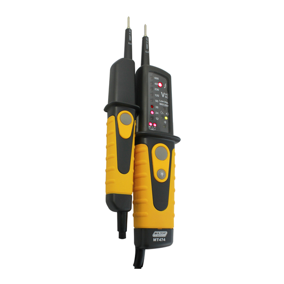
3. VOLTAGE TESTER DESCRIPTION 1 - Handle test probe - (L1) 8 - LED for continuity 2 - lnstrument test probe + (L2) 9 - Low impedance switch (L2) 3 - Measurement point illumination 10 - Measurement point lighting 4 - LEDs for voltage display Button 5 - LED for single-pole phase test 11 - Battery case... -
Page 8: Operation
5. OPERATION 5.1. Function test / Self test Ÿ Test the voltage tester on a known source. Ÿ Connect test probes. An acoustic sound must be audible and the LED (8) must be illuminated. Ÿ The voltage display of the instruments also functions when using discharged or no batteries. -
Page 9: Voltage Test With Rcd Trip Test
Ÿ The single-pole phase test starts at an AC voltage of approx. 100V (pole >100V AC). Ÿ When using single-pole phase tests to determine external conductors the display function may be impaired under certain conditions (e.g. for insulating body protective equipment on insulation locations). Ÿ... -
Page 10: Rotary Field Indication
5.7. Rotary Field Indication The voltage testers are equipped with a double-pole rotary field indicator. The rotary phase indication is always active. The symbols "R " or " L" are always displayed. However, the rotary direction can only be determined within a three-phase system. -
Page 11: Maintenance
5.9. Maintenance When using voltage testers in compliance with the instruction manual, no particular maintenance is required. If functional errors occur during normal operating, our service department will check your instrument without delay. 5.10. Cleaning Prior to cleaning, remove voltage test from all measurement circuits. If the instruments are dirty after daily usage, it is advisable to clean them by using a damp cloth and a mild household detergent. - Page 12 MAJOR TECH (PTY) LTD South Africa Australia www.major-tech.com www.majortech.com.au sales@major-tech.com info@majortech.com.au...
Need help?
Do you have a question about the MT474 and is the answer not in the manual?
Questions and answers