Inter-m R-150 Plus Operating Manual
Reference amplifier
Hide thumbs
Also See for R-150 Plus:
- Operation manual (35 pages) ,
- Wiring diagram (2 pages) ,
- Operation manual (35 pages)
Table of Contents
Advertisement
Advertisement
Table of Contents

Related Manuals for Inter-m R-150 Plus


Summary of Contents for Inter-m R-150 Plus
- Page 1 R150 PLUS/300 PLUS/500 PLUS CLIP PROT Reference Amplifier POWER R E F E R E N C E A M P L I F I E R CLIP PROT POWER OC03 OC03 B370031...
-
Page 2: Table Of Contents
Contents Contents Welcome Warning...1 Unpacking ...2 Short Form Instructions...2 Installation Environment...3 Important Safety Instructions...3 Description ...4 Features ...4 Accessories...4 Front Panel ...5 Rear Panel ...6 Mounting in a Rack ...7 Applications Stereo Installation ...8 Bridge Mono Installation ...9 Linked Installation...10 Connections ...11 Block Diagram... -
Page 3: Warning
A personal welcome to you from the management and employees of Inter-M All of the co-workers here at Inter-M are dedicated to providing excellent products with inherently good value, and we are delighted you have purchased one of our products. -
Page 4: Unpacking
REFERENCE AMPLIFIER Unpacking Please take a few minutes to read this manual to familiarize yourself with important information regarding installation, product features, and operation. As with most electronic devices, ORIGINAL PACKAGING (OR EQUAL) IS REQUIRED in the unlikely event that the product needs to be returned for servicing. -
Page 5: Installation
Installation Installation Environment Never place this product in an environment which could alter its performance or reduce its service life. Such environments usually include high levels of heat, dust, moisture, and vibration. Important Safety Instructions 1. Read these instructions. 2. Keep these instructions. 3. -
Page 6: Description
REFERENCE AMPLIFIER Description Description - R150 PLUS A 2U rack space, 2 channel amplifier capable of 150W into 8Ω load (bridged mono). - R300 PLUS A 2U rack space, 2 channel amplifier capable of 300W into 8Ω load (bridged mono). - R500 PLUS A 2U rack space, 2 channel amplifier capable of 500W into 8Ω... -
Page 7: Front Panel
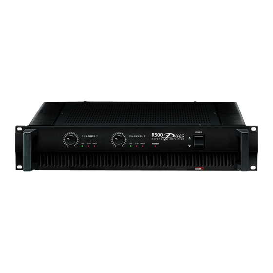
Front Panel Front Panel 1. LEVEL CONTROL This determines the level of the input signal for each channel. In stereo mode the knobs will determine the signal level independently for each channel. In the bridge mono mode only the channel 1 level control is used. 2. -
Page 8: Rear Panel
OF ELECTRIC SHOCK, BALANCED DO NOT REMOVE COVER. NO USER SERVICEABLE 0dBm PARTS INSIDE. REFER SERVICING TO QUALIFIED SERVICE PERSONNEL. CAUTION TO REDUCE THE RISK OF FIRE REPLACE ONLY WITH SAME TYPE FUSE. UTILISER UN FUSIBLE DE RECHANGE DE MEME TYPE. www.inter-m.com... -
Page 9: Mounting In A Rack
STEREO BRIDGED FIRE REPLACE ONLY WITH SAME TYPE FUSE. UTILISER UN FUSIBLE DE RECHANGE DE MEME TYPE. BRIDGED MONO (8 ~16 ) AC INPUT: 230V 50Hz,480W FUSE: T5AL/250V R150 PLUS/300 PLUS/500 PLUS REFERENCE AMPLIFIER INPUT CHANNEL 1 BALANCED 0dBm www.inter-m.com... -
Page 10: Stereo Installation
OF ELECTRIC SHOCK, BALANCED DO NOT REMOVE COVER. NO USER SERVICEABLE 0dBm PARTS INSIDE. REFER SERVICING TO QUALIFIED SERVICE PERSONNEL. CAUTION TO REDUCE THE RISK OF FIRE REPLACE ONLY WITH SAME TYPE FUSE. UTILISER UN FUSIBLE DE RECHANGE DE MEME TYPE. www.inter-m.com... -
Page 11: Bridge Mono Installation
OF ELECTRIC SHOCK, BALANCED DO NOT REMOVE COVER. NO USER SERVICEABLE 0dBm PARTS INSIDE. REFER SERVICING TO QUALIFIED SERVICE PERSONNEL. CAUTION TO REDUCE THE RISK OF FIRE REPLACE ONLY WITH SAME TYPE FUSE. UTILISER UN FUSIBLE DE RECHANGE DE MEME TYPE. www.inter-m.com... -
Page 12: Linked Installation
SERVICE PERSONNEL. CAUTION TO REDUCE THE RISK OF FIRE REPLACE ONLY WITH SAME TYPE FUSE. UTILISER UN FUSIBLE DE RECHANGE DE MEME TYPE. www.inter-m.com INPUT CAUTION CHANNEL 1 TO REDUCE THE RISK OF ELECTRIC SHOCK, DO NOT REMOVE COVER. BALANCED... -
Page 13: Connections
Connections Connections Inter-M products are wired to reflect accepted wiring practices used throughout the world. Balanced XLR connectors are wired as described: Pin #1 Shield Pin #2 Positive Pine #3 Negative Balanced 1/4" TRS connectors are wired as described: Tip is Positive... - Page 14 NOT CONNECTED BRIDGED MONO Positive R150 PLUS/300 PLUS/500 PLUS OUTPUT CHANNEL 2 CHANNEL 1 BRIDGED MONO (8 ~16 ) AMP OUTPUT CH1/CH2 Pin set #1 Wiring Diagram OUTPUT CHANNEL 2 CHANNEL 1 BRIDGED MONO (8 ~16 ) NOT CONNECTED Negative...
-
Page 15: Block Diagram
REFERENCE AMPLIFIER Block Diagram Block Diagram R150 PLUS/300 PLUS/500 PLUS... -
Page 16: Specifications
REFERENCE AMPLIFIER Specifications Specifications Power Output Level STEREO 8Ω(T.H.D 0.5%) 4Ω(T.H.D 0.5%) BRIDGED MONO 8Ω(T.H.D 0.05%) 8Ω(T.H.D 0.5%) Frequency Response T.H.D (20Hz~20kHz, half power) Channel Separation (half power 8Ω) Residual Noise Signal to Noise Ratio Input Sensitivity (rated power into 4Ω at 1kHz) Indicators Protection Power Source... -
Page 17: Service
To obtain specific warranty information and available service locations contact Inter-M directly or the authorized Inter-M Distributor for your specific country or region. - Page 18 NOTE...
- Page 19 Inter-M, Ltd. (Korea) began operations in 1983. Since then, Inter-M has grown to become one of the largest manufacturers of professional audio and commercial sound electronics equipment in the world. Inter-M has gained worldwide recognition for its own branded products, as well as private label manufacturing of electronics sold under other names (OEM).
Need help?
Do you have a question about the R-150 Plus and is the answer not in the manual?
Questions and answers