
Related Manuals for OKTANTA EM1401


Summary of Contents for OKTANTA EM1401
- Page 1 ЕМ1401UT_M_921807721 EM1401 / EM1401 UT Thickness Gauge Operation Manual Saint Petersburg +7(812) 385-54-28 info@oktanta-ndt.ru...
-
Page 2: Table Of Contents
EM1401 / EM1401 UT EMA Thickness Gauge. Operation Manual. CONTENTS CONTENTS ..........................2 INTENDED USE........................4 PRINCIPLE OF OPERATION ................... 4 TECHNICAL SPECIFICATIONS ..................5 OPERATION DESCRIPTION ................... 7 Device Switching On and Off ..................9 Information Display Mode Selection ..............10 Thickness Window...................... - Page 3 EM1401 / EM1401 UT EMA Thickness Gauge. Operation Manual. WARRANTY CERTIFICATE ..................51 INFORMATION ABOUT REPAIR ................52 INFORMATION ABOUT CALIBRATION TEST ..........53 +7(812) 385-54-28 info@oktanta-ndt.ru...
-
Page 4: Intended Use
EM1401 / EM1401 UT EMA Thickness Gauge. Operation Manual. INTENDED USE The EM1401 / EM1401 UT thickness gauge (further, the Device) is intended to measure thickness of steel pipe walls, flat steel, rods, and other products made of steel as well as aluminum and other metals using both non-contact electro-magnetic transducers and traditional contact piezoelectric transducers (for EM1401 UT version). -
Page 5: Technical Specifications
EM1401 / EM1401 UT EMA Thickness Gauge. Operation Manual. TECHNICAL SPECIFICATIONS For EMA transducer (EM1401, EM1401 UT) Measured thickness range for steel 2 to 80 mm Measured thickness range without gap for steel 2 to 120 mm Thickness measurement error 0.08 mm... - Page 6 EM1401 / EM1401 UT EMA Thickness Gauge. Operation Manual. Operating frequency 10 MHz for EDC10P5F3 5 MHz for EDC5P10FS15, EDC5P7.2FS10 Thickness measurement error 0.08 mm Maximum number of measurements per second Operating temperature range of the test object surface -5 to +50C...
-
Page 7: Operation Description
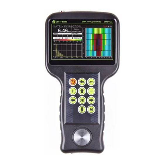
EM1401 / EM1401 UT EMA Thickness Gauge. Operation Manual. OPERATION DESCRIPTION Device Appearance Thickness gauge appearance At the top of the Device, there are a connector for EMA transducers and two connectors for PE transducers. The Device has a color liquid crystal display screen to display measurement results. - Page 8 EM1401 / EM1401 UT EMA Thickness Gauge. Operation Manual. Below are the functions of the control buttons. The On/Off button switches on/off the Device; The Back button allows the user to return to the previous menu items and to close the menu;...
-
Page 9: Device Switching On And Off
EM1401 / EM1401 UT EMA Thickness Gauge. Operation Manual. Device Switching On and Off To switch the Device on, press and hold the button during 3 s. A window with information about the Device software version appears on the display. -
Page 10: Information Display Mode Selection
EM1401 / EM1401 UT EMA Thickness Gauge. Operation Manual. Information Display Mode Selection The Device allows to visualize A-scan, B-scan, and C-scan. To switch between the information display modes, use the buttons Press the button once to switch to the A-scan display mode. -
Page 11: Thickness Window
EM1401 / EM1401 UT EMA Thickness Gauge. Operation Manual. C-scan display mode Press the button again to switch to the thickness display mode. Thickness Window The figure below shows the Thickness window. Thickness window The top of the screen displays the following information: ... - Page 12 EM1401 / EM1401 UT EMA Thickness Gauge. Operation Manual. Thickness measurement mode. Possible settings are as follows: auto, one strobe and two strobes; Averaging number used in the Device; Selected acoustic speed; Selected temperature of the test object;...
- Page 13 EM1401 / EM1401 UT EMA Thickness Gauge. Operation Manual. Transducer Selection The Device allows to select among four transducer types: EMAT: electromagnetic acoustic transducer. This setting shall be selected when any EMA transducer is used. EDC10P5F3: piezoelectric transducer to measure thickness ranging from 0.5 to 20 mm.
- Page 14 EM1401 / EM1401 UT EMA Thickness Gauge. Operation Manual. Accumulation Number Selection By default, the Device uses 128 accumulations. Thus, the final thickness measurement is performed using 128 measured values by averaging them. When the test object has a poor surface quality or heavy corrosion, increase the number of accumulations up to 256-512.
- Page 15 EM1401 / EM1401 UT EMA Thickness Gauge. Operation Manual. by calculating delay in prism which sizes constantly decrease as the transducer wears out. When this item is selected, the Device window will be as follows: Sensor calibration When the Calibration text appears on the screen, put the sensor on the calibration sample coated with contact liquid.
- Page 16 EM1401 / EM1401 UT EMA Thickness Gauge. Operation Manual. In the opened window, press the , and buttons to specify the known thickness value; then press the button. Speed. This item enables to specify the acoustic speed. The acoustic speed setting window is shown below:...
- Page 17 EM1401 / EM1401 UT EMA Thickness Gauge. Operation Manual. set the test object temperature in this menu. The window used to enter the test object temperature is shown in Figure below. Test object temperature entry In this window, press the...
-
Page 18: A-Scan Window
EM1401 / EM1401 UT EMA Thickness Gauge. Operation Manual. Test object material selection To select the required material, use the buttons/ A-scan window The A-scan window appearance is shown in Figure below: A-scan appearance +7(812) 385-54-28 info@oktanta-ndt.ru... - Page 19 EM1401 / EM1401 UT EMA Thickness Gauge. Operation Manual. A-scan Scale Change The user can change the scale of the A-scan display. To change the scale, press button or the button while being in the A-scan window. In this case, SCALE appears on the screen...
- Page 20 EM1401 / EM1401 UT EMA Thickness Gauge. Operation Manual. Context ("OK") menu To close the context menu, change one of the menu settings by pressing the button, or press the button. Thickness Measurement Algorithm Selection The Device has three thickness measurement algorithms: an automatic algorithm, a thickness measurement algorithm using one strobe and a thickness measurement algorithm using two strobes.
- Page 21 EM1401 / EM1401 UT EMA Thickness Gauge. Operation Manual. Thickness measurement algorithm selection Accumulation Number Selection By default, the Device uses 128 accumulations of the useful signal and calculates thickness using the average values. When the Device measures thickness of...
- Page 22 EM1401 / EM1401 UT EMA Thickness Gauge. Operation Manual. Note that increase of the accumulation number will increase the measurement time. A-scan View Change The Device can display the A-scan in three ways: the original bipolar signal, the detected signal and the filtered signal (envelope filter).
- Page 23 EM1401 / EM1401 UT EMA Thickness Gauge. Operation Manual. Gain level indicator position In the manual mode, the gain level is controlled using the buttons. To return to the automatic gain control mode, select the setting On in the AGC context menu/ The upper part of the gain control indicator will become blue again.
- Page 24 EM1401 / EM1401 UT EMA Thickness Gauge. Operation Manual. Strobe information display The position and length of each strobe can be changed To do this, open the Strobes menu by pressing the button. Then, the red strobe is highlighted on the display...
- Page 25 EM1401 / EM1401 UT EMA Thickness Gauge. Operation Manual. Blue strobe selection You can set the position and length of the blue strobe in the same way as those of the red strobe by pressing the , and buttons. Upon selection of the position and length of the blue strobe, press the button.
- Page 26 EM1401 / EM1401 UT EMA Thickness Gauge. Operation Manual. by calculating delay in prism which sizes constantly decrease as the transducer wears out. When this item is selected, the Device window will be as follows: Sensor calibration When the Calibration text appears on the screen, put the sensor on the calibration sample coated with contact liquid.
-
Page 27: B-Scan Window
EM1401 / EM1401 UT EMA Thickness Gauge. Operation Manual. In the opened window, press the , and buttons to specify the known thickness value; then press the button. Speed. This item enables to specify the acoustic speed. The acoustic speed setting window is shown below:... - Page 28 EM1401 / EM1401 UT EMA Thickness Gauge. Operation Manual. B-scan window appearance At the top of this window, the A-scan with two thresholds (blue and red) is displayed. At the bottom, the B-scan is displayed. All A-scan points which values are lower than the blue threshold position are displayed on the B-scan in light-blue.
- Page 29 EM1401 / EM1401 UT EMA Thickness Gauge. Operation Manual. B-scan scale change mode In this mode, you can change the B-scan scale using the buttons you can also change the display area using the buttons. Upon selection of the position and size of the scaled area, press the...
- Page 30 EM1401 / EM1401 UT EMA Thickness Gauge. Operation Manual. B-scan filling mode selection You can select two options in this window: stand-by mode and continuous mode. When the standby mode is selected, the B-scan will not be updated until the user presses the button.
- Page 31 EM1401 / EM1401 UT EMA Thickness Gauge. Operation Manual. B-scan filling time selection The user can select in what number of times the time of B-scan updating is greater than the standard value. Thresholds The Device has two adjustable thresholds. To adjust the thresholds position,...
- Page 32 EM1401 / EM1401 UT EMA Thickness Gauge. Operation Manual. You can move the highlighted threshold using the buttons. When you press the button once again, the blue threshold will become highlighted instead of the red one. Its position can be adjusted as well using the buttons.
-
Page 33: C-Scan Window
EM1401 / EM1401 UT EMA Thickness Gauge. Operation Manual. B-scan appearance, option 2 B-scan appearance, option 3 C-scan Window The Device can save data as the C-scan. The C-scan window appearance is shown in the Figure below: +7(812) 385-54-28 info@oktanta-ndt.ru... - Page 34 EM1401 / EM1401 UT EMA Thickness Gauge. Operation Manual. C-scan window appearance This window consists of three items: Start inspection; Open inspections; Continue inspection. To navigate through these three items, use buttons To return from any selected item, press on the button.
- Page 35 EM1401 / EM1401 UT EMA Thickness Gauge. Operation Manual. Start Inspection window appearance, Pipe test object If the user selects "Matrix" as the test object, then the appearance of this window will be as shown below: Start Inspection window appearance, Matrix test object You can navigate through this window using the buttons.
- Page 36 EM1401 / EM1401 UT EMA Thickness Gauge. Operation Manual. Test object name entering To enter symbols, letters, and numbers in this window, use the buttons. Upon completion, press the button. For the object of the "Pipe" type, set the necessary number of the measured points in one ring as well as number of rings along the pipe.
- Page 37 EM1401 / EM1401 UT EMA Thickness Gauge. Operation Manual. Then, the window appearance will be as shown in the Figures below: C-scan filling mode for "Matrix" test object C-scan filling mode for "Pipe" test object This window shows the A-scan, C-scan, current value of the measured thickness, current coordinate, as well as the minimum thickness which was found during the whole time of C-scan filling.
- Page 38 EM1401 / EM1401 UT EMA Thickness Gauge. Operation Manual. To fill the C-scan, the user installs the Device sensor in the required point and presses the button; the cursor coordinate increases by one increment and the procedure repeats. Open inspections This item enables to open the previously saved inspection results.
-
Page 39: User Menu
EM1401 / EM1401 UT EMA Thickness Gauge. Operation Manual. Delete This item enables to select and delete the previously saved archive. Delete all This item enables to delete all archives saved in the Device memory. Continue inspection This item becomes active when the user has started the inspection earlier and has terminated it by switching to the other windows of the Device. - Page 40 EM1401 / EM1401 UT EMA Thickness Gauge. Operation Manual. This menu contains the following menu items: Date This item enables to set the current date. To change the value, press the buttons. Time This item enables to set the current time. To change the value, press the buttons.
-
Page 41: Transducer Selection
EM1401 / EM1401 UT EMA Thickness Gauge. Operation Manual. Brightness This item enables to set the percentage screen brightness. To change the value, press the buttons. Restore default This item enables to restore all defaults of the Device. To select this menu item, press on the button. -
Page 42: Thickness Measurements Using The Device
EM1401 / EM1401 UT EMA Thickness Gauge. Operation Manual. The transducer has a steel housing and special heat-resistant protector and is from -20 to from 2 to from 0 to EMT14014T designed for operation with the objects +750 120 mm heated up to 750 C. -
Page 43: Data Transfer To Pc
EM1401 / EM1401 UT EMA Thickness Gauge. Operation Manual. Press the button to switch the Device on. When no test object is near the transducer, the thickness values on the Device screen can change randomly. If necessary, calibrate the Device (see section "Calibration", item "Thickness window") -
Page 44: Device Operation Features
EM1401 / EM1401 UT EMA Thickness Gauge. Operation Manual. Device Operation Features The Device has the electromagnetic-acoustic transducer with a permanent magnet that introduces a number of requirements for operation with the Device Be careful when moving the transducer near knives, forks, needles, and other sharp metal objects. -
Page 45: Device Calibration Test Procedure
EM1401 / EM1401 UT EMA Thickness Gauge. Operation Manual. Battery charge indicator It takes at least five hours to charge a fully discharged battery to 100%. Charge the Device when it is off. WARNING! Long-term storage of the Device battery in the fully discharged state can decrease battery capacity and reduce its service life. - Page 46 EM1401 / EM1401 UT EMA Thickness Gauge. Operation Manual. Calibration Test Procedure During the calibration test, the following operations should be performed: External examination; Functional test; Measurement error calculation. In agreement with the bodies conducting the Device calibration test, the calibration test may be performed not in full.
- Page 47 EM1401 / EM1401 UT EMA Thickness Gauge. Operation Manual. Humidity 80% at +25 C Atmosphere pressure 86 to 106 kPa Calibration Test Description External examination The following requirements are checked during the external examination: The scope of the Device supply shall be as specified in the operation manual;...
-
Page 48: Maintenance
EM1401 / EM1401 UT EMA Thickness Gauge. Operation Manual. 5. Repeat the operations specified in items 1 to 4 for 10 and 60 mm thick test samples. The calibration test results are considered positive if the obtained values of the Device measurement error for all test samples do not exceed ±... -
Page 49: Transportation And Storage
EM1401 / EM1401 UT EMA Thickness Gauge. Operation Manual. TRANSPORTATION AND STORAGE During storage and transportation of the Device, maintain the following climatic conditions: Air temperature: +5 to +30 С Humidity 80% at +25 C Store and transport the Device only in a case from the scope of supply. Avoid any mechanical damages of the case and Device. -
Page 50: Scope Of Supply
EM1401 / EM1401 UT EMA Thickness Gauge. Operation Manual. SCOPE OF SUPPLY Basic configuration EM1401 thickness gauge 1 pc. Storage case 1 pc. Recharger 1 pc. EMT1402 transducer 1 pc. Connecting cable 1 pc. Operation Manual 1 pc. Protective cover 1 pc. -
Page 51: Manufacturer Warranty
EM1401 / EM1401 UT EMA Thickness Gauge. Operation Manual. MANUFACTURER WARRANTY The warranty period is 24 months from the purchase date. Within the warranty period, the Manufacturer shall rectify faults of the Device provided that the housing is not damaged and the warranty seals are available. - Page 52 EM1401 / EM1401 UT EMA Thickness Gauge. Operation Manual. INFORMATION ABOUT REPAIR Completed/Not Date of Completed Fault Type Repair Application (Date, Signature, Stamp) +7(812) 385-54-28 info@oktanta-ndt.ru...
- Page 53 EM1401 / EM1401 UT EMA Thickness Gauge. Operation Manual. INFORMATION ABOUT CALIBRATION TEST Date of calibration test Valid till Calibrator +7(812) 385-54-28 info@oktanta-ndt.ru...
Need help?
Do you have a question about the EM1401 and is the answer not in the manual?
Questions and answers