
Related Manuals for OKTANTA PE1437


Summary of Contents for OKTANTA PE1437
- Page 1 PEC Flaw Detector PE1437 Operation Manual Saint Petersburg 2022 +7(812) 385-54-28 info@oktanta-ndt.ru...
-
Page 2: Table Of Contents
PEC Flaw Detector PE1437. Operation Manual CONTENTS PURPOSE ............................4 PRINCIPLE OF OPERATION ........................7 TECHNICAL SPECIFICATIONS ....................... 8 OPERATION DESCRIPTION ........................9 Device appearance ......................... 9 Device switching on and off......................11 Selection of information display mode ..................12 Thickness window .........................14 Calibration ..........................15... - Page 3 PEC Flaw Detector PE1437. Operation Manual Battery replacement .........................45 TRANSPORTATION AND STORAGE .....................46 SCOPE OF SUPPLY ..........................46 MANUFACTURER WARRANTY ......................47 INFORMATION ABOUT REPAIR ......................48 +7(812) 385-54-28 info@oktanta-ndt.ru...
-
Page 4: Purpose
PEC Flaw Detector PE1437. Operation Manual PURPOSE The Pulsed Eddy Current Flaw Detector PE1437 (PEC Flaw Detector PE1437) is designed to detect corrosion under insulation, through a thick layer of paint, and through a layer of corrosion deposits and mud. - Page 5 PEC Flaw Detector PE1437. Operation Manual Ultimate thinning detection on objects sensitive to strong corrosion Corrosion detection through a thick layer of epoxy paint aboard ships Corrosion detection on pipes and pipelines with inner coating, for example, concrete or cement one (with access from the inner side of the test object).
- Page 6 PEC Flaw Detector PE1437. Operation Manual Corrosion detection in different steel supports, for example, street lamp supports or electrical grid supports The Device allows testing without preliminary surface preparation or insulation removal. The insulation can be represented with any non-conducting coating, such as polyurethane, mineral wool, plastics, paint, air, concrete, mud, bitumen, stone, or corrosion deposits.
-
Page 7: Principle Of Operation
PEC Flaw Detector PE1437. Operation Manual PRINCIPLE OF OPERATION The Device operation is based on the pulsed eddy current technique of nondestructive inspection. A Device sensor generates a pulsed magnet field which magnetizes an area of the test object located beneath it. Time of magnetization and demagnetization of this area depends on the metal thickness. -
Page 8: Technical Specifications
PEC Flaw Detector PE1437. Operation Manual TECHNICAL SPECIFICATIONS Measured thickness range for steel 0 to 12 mm (for PEC143702) Measured thickness range for steel 0 to 18 mm (for PEC143703) Average thickness measurement error Insulation thickness range 0 to 30 mm... -
Page 9: Operation Description
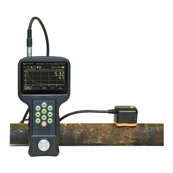
PEC Flaw Detector PE1437. Operation Manual OPERATION DESCRIPTION Device appearance Sensor connector Display Membrane keyboard Recharger connector USB connector Device Appearance On the top of the Device, there is a sensor connector. The measurement results are displayed on a color liquid crystal display. The Device is controlled by a membrane keyboard. - Page 10 PEC Flaw Detector PE1437. Operation Manual Functions of the control buttons are described in the table below. The On/Off button switches on/off the Device The Back button returns you to the previous menu items The Menu button opens/closes the Device menu...
-
Page 11: Device Switching On And Off
PEC Flaw Detector PE1437. Operation Manual Device switching on and off To switch the Device on, press and hold the button during several seconds. Then, the Device will switch on and its display will show a window with information about the Device software version during several seconds. -
Page 12: Selection Of Information Display Mode
PEC Flaw Detector PE1437. Operation Manual Selection of Information Display Mode The Device has three main options to display information: Thickness display mode which displays only the measured thickness of the test object; A-scan display mode enabling the user to monitor a shape of the demagnetization process curve; and C-scan display mode enabling to measure test object area with saving the data in the matrix format. - Page 13 PEC Flaw Detector PE1437. Operation Manual A-scan display mode With double pressing the button you can change over to the C-scan display mode. C-scan display mode To return the Device to the Thickness display mode, press the button again. +7(812) 385-54-28...
-
Page 14: Thickness Window
PEC Flaw Detector PE1437. Operation Manual Thickness window The Figure below shows the Thickness window. Thickness window The top of the screen displays the following information: Sensor name; Metal thickness specified during Device calibration; Insulation thickness (gap) specified during calibration. -
Page 15: Calibration
PEC Flaw Detector PE1437. Operation Manual With this submenu, the user can calibrate the Device, change the sensor and select the number of accumulations. To navigate between the parameters in the Thickness window, you can use the buttons. To confirm the selected parameter, press the button. -
Page 16: Sensor Selection
PEC Flaw Detector PE1437. Operation Manual To save the specified parameters, use the button. After pressing the button, hold the Device sensor motionless relative to the test object for several seconds during calibration. Sensor selection With the Sensor submenu, the user can change the sensor type. The number of the sensors depends on the Device scope of supply. -
Page 17: A-Scan Window
PEC Flaw Detector PE1437. Operation Manual confirm your selection by pressing the button. By default, the Device use only one accumulation. For example, if three accumulations are selected for the Device, it will take three demagnetization curves at one point of the test object and plot the new averaged curve. -
Page 18: Scale Change
PEC Flaw Detector PE1437. Operation Manual Scale change The user can change the scale of the A-scan display. To change the scale, press the button while being in the A-scan window. Then, a word “SCALE” will appear in the A-scan window. -
Page 19: Calibration
PEC Flaw Detector PE1437. Operation Manual In the A-scan window, the user can calibrate the Device, change the sensor type and the number of accumulations. These parameters can be changed in the submenu which appears with pressing the button in the same way as described for the Thickness window. -
Page 20: Sensor Selection
PEC Flaw Detector PE1437. Operation Manual Calibration in A-scan mode To calibrate the Device, do as follows: Install the Device sensor on the test object in the point where you know the metal thickness and insulation thickness; In the Calibrate window, enter values of the metal and insulation thicknesses. To enter the values, use the buttons. -
Page 21: C-Scan Window
PEC Flaw Detector PE1437. Operation Manual measurements, however, they reduce the Device operation speed. The Figure below shows the window for selecting the number of accumulations Selection of number of accumulations in A-scan window By using the buttons, the user can change the number of accumulations To confirm changes, press the button. - Page 22 PEC Flaw Detector PE1437. Operation Manual measurements in the grid nodes. We produce the special self-adhesive grid which can be attached to the test object. The example of such grid is shown in Figure below: Example of self-adhesive grid produced by Oktanta You can manually draw the grid on the test object using a ruler and a marker, however, we do not recommend this method as it requires a lot of time.
-
Page 23: Start Measurements
PEC Flaw Detector PE1437. Operation Manual This window consists of three menu items: Start measurements. This menu item is used to start filling of the new C- scan. Open C-scan. This menu item is used to open the saved C-scans. - Page 24 PEC Flaw Detector PE1437. Operation Manual You can navigate through this window using the buttons. You can change the parameters using the buttons. Object selection The device has objects of two types: a grid and a pipe. The difference between them is as follows: the pipe-type object is extended along the horizontal axis and the grid-type object occupies a square-like area.
- Page 25 PEC Flaw Detector PE1437. Operation Manual C-scan for pipe-type object Object name entering To enter the name of the object, select this menu item using the buttons and press the button. In this case, the window shown in Figure below...
- Page 26 PEC Flaw Detector PE1437. Operation Manual To enter symbols, letters, and numbers in this window, use the buttons. To enter the selected symbol, letter, digit, press the button. To save the object name, select the “Enter” symbol on the soft keyboard and press the button.
- Page 27 PEC Flaw Detector PE1437. Operation Manual Minimum thickness and nominal thickness The user must enter the nominal thickness of the test object and minimum permissible thickness of the test object. In the course of the C-scan filling, all points with thicknesses less than the minimum permissible thickness will be displayed in black.
-
Page 28: Open C-Scan
PEC Flaw Detector PE1437. Operation Manual C-scan filling mode for pipe-type object This window shows the A-scan, C-scan, current value of the measured thickness, current coordinate, as well as the minimum thickness which was found during the whole time of C-scan filling. -
Page 29: Continue Measurements
PEC Flaw Detector PE1437. Operation Manual Open C-s window You can navigate through the menu items using the buttons. To select the appropriate menu item, press the button. Continue measurements This menu item becomes active when the user has started the inspection earlier and has terminated it by switching to the other windows of the Device. - Page 30 PEC Flaw Detector PE1437. Operation Manual User menu To navigate through the menu items, use the buttons. Date Set the current date using the buttons. Time This menu item enables to set the current time. To change the value, use the buttons.
- Page 31 PEC Flaw Detector PE1437. Operation Manual Language This menu item enables to select the Device interface language. Available options are Chinese, English, and Russian. To change the language, use the buttons. Units To change the measurement units, use the buttons.
- Page 32 PEC Flaw Detector PE1437. Operation Manual Restore default window To change over between the “Yes” and “No” buttons, use the buttons. To confirm your selection, press the button. About This menu item displays the software version and name of the Device. To select this menu item, press the button.
-
Page 33: Thickness Measurement And Faults Detection
Prior to operation beginning, select the sensor suitable for this test object. Sensor selection The PEC Flaw Detector PE1437 can operate with two main sensors: PEC143702 and PEC143703. The standard scope of Device supply includes one sensor PEC143702. The sensor shall be selected depending on the thickness range to be tested and insulation thickness range. - Page 34 PEC Flaw Detector PE1437. Operation Manual The Figure below shows a diagram for sensor selection depending on the above parameters. Diagram for sensor selection The larger is the thickness range and insulation thickness range, the larger is the sensor. The sensor measures the averaged thickness beneath it, and therefore, the larger is the sensor, the larger is the area over which the averaging takes place and, accordingly, the larger is the minimum fault that the device can detect.
- Page 35 PEC Flaw Detector PE1437. Operation Manual above diagram, you shall use sensor PEC143703, and sensor PEC143702 will not be suitable in this case. Average thickness measurement area The Device measures the average thickness in a certain area under the sensor.
- Page 36 For correct operation of PE1437, select measurement area located from the edge at a distance equal to double insulation thickness or more. The example of such sensor location is shown in the Figure below.
-
Page 37: Thickness Measurement
2 x G from each of the above items. Thickness measurement The PE1437 measures thicknesses by analyzing the metal demagnetization speed under the sensor. The demagnetization process is displayed on A-scan. An example of A-scan is shown in the Figure below... - Page 38 4 accumulations(see "Change of number of accumulations"). Any thickness measurement to be carried out with PE1437 is performed relative to the known thickness in a certain point of the test object. Therefore, prior to the thickness measurements, it is necessary to calibrate the Device for this test object.
-
Page 39: C-Scan Filling Mode
PEC Flaw Detector PE1437. Operation Manual . The Device will measure the thickness, and the measured value will be displayed on the Device screen. You can start the continuous measuring mode using the button. In this mode, the Device performs thickness measurements periodically; it updates the readings on the Device screen each time after measuring. - Page 40 PEC Flaw Detector PE1437. Operation Manual You can manually draw the grid on the test object using a ruler and a marker, however, we do not recommend this method as it requires a lot of time. Select the C-scan window in the Device menu (see Section “C-scan window”).
- Page 41 PEC Flaw Detector PE1437. Operation Manual C-scan filling procedure Then, move the sensor to the appropriate next node and re-press the button. Then, the following measurement will appear on the C-scan: C-scan filling procedure As a result, the whole C-scan will be filled step-by-step.
-
Page 42: Data Transfer To Pc
PEC Flaw Detector PE1437. Operation Manual C-scan filling procedure The black cells on the C-scan mean that there are thicknesses less than the minimum permissible one. After saving the C-scan can be opened on the Device or read it using the software on the PC. -
Page 43: Device Operation Features
PEC Flaw Detector PE1437. Operation Manual PE1437_Downloader application To download the files, connect the Device to the PC with the installed PE1437_Downloader application, start up the application, switch on the Device, select the thickness measurement units and press the button in the top left angle of the application. -
Page 44: Battery Charge
PEC Flaw Detector PE1437. Operation Manual 3. Do not place the sensor near working electronic devices and tools. The pulsed field generated by the sensor can interfere with electronics operation. 4. If the sensor cable is damaged, replace the sensor with a new one. -
Page 45: Maintenance
PEC Flaw Detector PE1437. Operation Manual It takes at least five hours to charge a fully discharged battery to 100%. Charge the Device when it is off. WARNING! Long-term storage of the Device battery in the fully discharged state can decrease battery capacity and reduce its service life. -
Page 46: Transportation And Storage
PEC Flaw Detector PE1437. Operation Manual TRANSPORTATION AND STORAGE During storage and transportation of the Device, maintain the following climatic conditions: +5 to +30 C Air temperature 80 % at +25 C Humidity Store and transport the Device only in a case from the scope of supply. Avoid any mechanical damages of the case and Device. -
Page 47: Manufacturer Warranty
PEC Flaw Detector PE1437. Operation Manual MANUFACTURER WARRANTY The warranty period for the Device is 2 years from the purchase date. Within the warranty period, the Manufacturer shall rectify faults of the Device provided that the housing is not damaged and the warranty seals are available. -
Page 48: Information About Repair
PEC Flaw Detector PE1437. Operation Manual INFORMATION ABOUT REPAIR Completed/Not Completed (Date, Date of Fault Type Repair Signature, Stamp) Application +7(812) 385-54-28 info@oktanta-ndt.ru...
Need help?
Do you have a question about the PE1437 and is the answer not in the manual?
Questions and answers