
Related Manuals for Prominence Home 51428


Summary of Contents for Prominence Home 51428
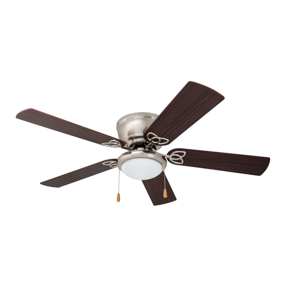
- Page 1 52-INCH HUGGER FAN MODELS #51428, 51429 Questions, problems or missing parts? Before returning this item to your retailer, call our customer service department at 1-877-706-3267, Monday - Thursday, 8am - 6pm, Friday, 8am - 5pm EST.
-
Page 2: Package Contents
PACKAGE CONTENTS HARDWARE CONTENTS (not drawn to scale) Motor Housing Pull Chain Extension (x 2) Wire Connector (x 3) Mounting Bracket Lower Bracket Blade Screw (x 15) Motor Blade (x 5) Blade Arm (x 5) Blade Washer (x 15) Switch Housing Light Kit Plug Button Bulb... -
Page 3: Table Of Contents
TABLE OF CONTENTS Package Contents ..................... 2 Preparation . - Page 4 PREPARATION Downrod Mounting Angle Mounting Flushmount Closemount 1. Turn off power. 2. Choose mounting option. 3. Choose suitable location. Turn off the power to the fan at the breaker Ensure the blades will be at least 30 inches Standard Mounting installation is not box and the wall switch.
-
Page 5: Assembly Instructions
ASSEMBLY INSTRUCTIONS Mounting Outlet Box Bracket Mounting Bracket Mounting Bracket Slots Hook Lower Bracket Bracket Screws Lower Bracket Bracket Screw 1. Install the mounting bracket. 2. Attach the lower bracket. 3. Secure the lower bracket. Secure the mounting bracket to the outlet Note: Remove the wire restraint from the Secure the lower bracket to the mounting box (not included) using the washers and... - Page 6 ASSEMBLY INSTRUCTIONS Mounting Bracket Screw Blade Screw Black (live) x 15 Blade Washer White (neutral) Bare/Green (ground) Blade Arm Note: If there is a second hot supply wire coming from the outlet box, connect it to the blue (light power) fan wire for separate light and fan control.
- Page 7 ASSEMBLY INSTRUCTIONS x 10 Switch Housing Screw Switch Single-pin Housing Connector Screw Motor Screw Light Kit Light Kit Blade Arm 7. Attach blade arms to motor. 8. Connect light kit wiring. 9. Attach light kit to switch housing. Remove the ten motor screws from the Remove the three switch housing screws underside of the motor.
- Page 8 ASSEMBLY INSTRUCTIONS Chain Guide Light Kit Spring Clip Bulb Glass Bowl Pull Chain Extension 12. Attach pull chain extensions. 10. Install the two E26-base LED 11. Install glass bowl. bulbs. Attach the glass bowl by inserting the three Feed the pull chains down through the chain Important: When replacing bulbs, allow spring clips inside the neck of the glass bowl guides in the light kit and attach the pull...
-
Page 9: Installation Without Light Kit
INSTALLATION WITHOUT LIGHT KIT (optional) Switch Housing Switch Housing Screw Switch Housing Cap Pull Chain Extension 1. Install switch housing cap to 2. Attach pull chain extension. switch housing. When facing the reverse switch, the light pull chain will be on the left and the fan pull Remove the three switch housing screws chain will be on the right. -
Page 10: Operating Instructions
OPERATING INSTRUCTIONS Light Pull Fan Pull Chain Chain Reverse Switch Reverse Switch 1. Pull chain operation. 2. Reverse switch operation. When facing the reverse switch, the light Use the fan reverse switch, located on the pull chain will be on the left and the fan pull switch housing to optimize your fan for chain will be on the right. -
Page 11: Safety Information
SAFETY INFORMATION Please read and understand this entire manual before attempting to assemble, operate or install the product. • Before you begin installing the fan, disconnect the power by removing fuses or turning off the circuit breakers. • Make sure all electrical connections comply with local codes, ordinances, the National Electrical Code and ANSI/NFPA 70-199. Hire a qualified electrician or consult a do-it-yourself wiring handbook if you are unfamiliar with installing electrical wiring. -
Page 12: Troubleshooting
TROUBLESHOOTING PROBLEM CORRECTIVE ACTION The fan does not move. 1. Firmly push the reverse switch completely up or down. 2. Make sure the wall switch is turned on. 3. Ensure power is on at wall switch and breaker box 4. Turn the power off and check all wire connections at the ceiling outlet box. 1. -
Page 13: Warranty
LIFETIME LIMITED WARRANTY The manufacturer warrants this fan to be free from defects in workmanship and materials present at time of shipment from the factory for a lifetime from the date of purchase by the original purchaser. The retailer also warrants that all other fan parts, excluding any glass or acrylic blades, to be free from defects in workmanship and material at the time of shipment from the factory for a period of one year after the date of purchase by the original purchaser. -
Page 14: Replacement Parts List
REPLACEMENT PARTS LIST For replacement parts, call our customer service department at 1-877-706-3267, Monday - Thursday, 8am - 6pm, Friday 8am - 5 pm, EST. 51428 51429 Motor Housing 4L000007740 4L000007750 Mounting Bracket 4L000007760 4L000007770 Light Kit 4A000009390 4A000009410 Glass Bowl...
Need help?
Do you have a question about the 51428 and is the answer not in the manual?
Questions and answers