
Related Manuals for SEGUE VK-1965


Summary of Contents for SEGUE VK-1965
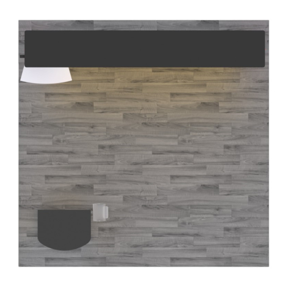
- Page 1 © 2017 Order #XXXXX VK-1965 General Layout Plan View SETUP INSTRUCTIONS w w w . c l a s s i c e x h i b i t s . c o m If you would like to tell us about your experience with your setup instructions please email us at info@classicexhibits.com...
-
Page 2: General Setup Instructions
© 2017 Order #XXXXX General Information General Setup Instructions - Read entire setup instruction manual prior to WARNING unpacking parts and pieces. - The setup instructions are created specifically for this configuration. - Setup instructions are laid out sequentially in steps, including exploded views with detailed explanation for assembly. - Page 3 © 2017 Order #XXXXX CEi-110 Assembly Straight Connection CEI-110 Frames Assembly TS RV 4 Insert Bracket Slide connecting Bracket into the Interior extrusion over Straight Bracket Installation Center Slot exposed end (when required) of extrusion. of bracket. 1) Slide TWO-PIECE TS RV 4 straight bracket into Interior Center Slot of extrusion so that two of the...
- Page 4 © 2017 Order #XXXXX Case Packing Top View of Each Level Counter Top Wings Shelf Base Plates (2x) 10/11 Level 1 Level 2 Level 3 Level 4 Level 5 w w w . c l a s s i c e x h i b i t s . c o m Case 1 of 3...
- Page 5 © 2017 Order #XXXXX Case Packing Top View of Each Level Shelf Assembled Assembled Assembled Counter Counter Counter Infills Counter Side Side Door Shelf Supports Level 1 Level 2 Level 3 Level 4 Level 5 Level 6 w w w . c l a s s i c e x h i b i t s . c o m Case 2 of 3...
- Page 6 © 2017 Order #XXXXX Case Packing Canopy Pieces in Bag Graphics Literature Holders & Monitor Mount Setup Hardware Level 1 w w w . c l a s s i c e x h i b i t s . c o m Case 3 of 3...
- Page 7 © 2017 Order #XXXXX Backwall Assembly Item Qty. Description Steps: Base Plate 1) Attach Base Plates [1] to lower Vertical Extrusions [2] and [3], using bolts. 2/2A 46” CEI-110 Horizontal Extrusion 2) Connect Horizontal Extrusions [2,2A] [3,3A] and Vertical Extrusions 3/3A 46”...
-
Page 8: Push Button
© 2017 Order #XXXXX Canopy Asssembly Steps: 1) Connect canopy pieces together as shown. 2) Apply pillow case graphic to assembled canopy. Using Your Setup Instructions The Aero Overhead Sign Setup Instructions are created specifically for your configuration. They include an exploded view of the frame which is sequentially numbered. - Page 9 A10 Clamp detail. 7) Attach assembled Canopy to top of Horizontal assembly [3/3A]. 8) Attach Monitor Mount to Vertical Extrusion [4A], using Connectors. Monitor Mount detail. Canopy Completed VK-1965 Assembly A10 Clamp (Front View) Connector Monitor Mount Counter Top Attachment Monitor...
- Page 10 © 2017 Order #XXXXX Modified MOD-1551 Assembly Item Qty. Description Steps: 38” RSG520 Vertical Extrusion 1) Connect lower horizotnals [5] & [6] between verticals [1,2,3,4]. 38” RSG520 Vertical Extrusion 2) Place Infills between verticals [1,2,3,4], with Velcro facing inward. 38” RSG520 Vertical Extrusion 3) Connect Shelf Supports to Velcro inside of Infills, then place Shelf...
Need help?
Do you have a question about the VK-1965 and is the answer not in the manual?
Questions and answers