Table of Contents
Advertisement
Quick Links
Advertisement
Table of Contents

Related Manuals for 3DLab GANG PRINT BEAT MACCHI MC.200

Summary of Contents for 3DLab GANG PRINT BEAT MACCHI MC.200
-
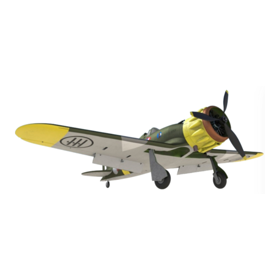
Page 2: Model Specification
member of Group ASSEMBLY INSTRUCTION FOR RC MODEL PRINTED ON 3D PRINTER Visit our website www.print-beat.com and purchase a product which you are interested in. Then you get an access for the file download in g-code or STL format. Download the files onto SD card. We try to optimize the universal G-code output for the widest selection of printers and we test our products on several printer brands and configurations. - Page 3 member of Group WHATEVER YOU NEED PLA filament for print model parts and FLEX filament for print tire Super glue and Activator 2x Servoless Retractable System from HobbyKing.com Link 6X Metal Gear Micro Servos (Recommended Turnigy TGY-9018MG) Link Screws diameter 4xM3/12mm 2xM3/25mm 1x M3/15mm 5x Nut M3 2x Nylon Screw M4/25mm Link...
- Page 4 member of Group PRINTED PARTS LIST No. Parts name Layer H. Weight Infil Suport E. Multiplier Perimeter Main Location 1 Fuselage A 0,20mm 0,86 Fuselage_01_-_07 2 Fuselage B 0,25mm 0,86 Fuselage_01_-_07 3 Fuselage C 0,25mm 0,86 Fuselage_01_-_07 4 Fuselage D 0,25mm 0,86 Fuselage_01_-_07...
- Page 5 member of Group PRINTED PARTS LIST 44 Ring 0,25mm Engine_40_-_49 45 Motor Body 0,25mm 0,84 Engine_40_-_49 46 Cylinder Front 0,25mm 0,84 Engine_40_-_49 47 Cylinder Back 0,25mm 0,84 Engine_40_-_49 48 OHV Timing Rod 0,25mm Engine_40_-_49 49 Exhaust 0,25mm Engine_40_-_49 50 Wing Left A 0,19mm 0,86 Wing_50_-_74...
-
Page 6: Fuselage Assembly
member of Group FUSELAGE ASSEMBLY Fuselage Assembly: We start with gluing parts of the fuselage (-01-02-03-04-05&-06) together by use of Super Glue (do not glue the last part of the fuselage -07) NOTE: Before gluing each part, clean the holes in the middle of the fuselage reces. - Page 7 member of Group TAILPLANE & ELEVATORS Glue left part of the tailplane (-8)
- Page 8 member of Group TAILPLANE & ELEVATORS Elevators: A ach the bowden servo cable to the lever on the elevator sha (-15 & -16). Insert the elevator sha (-15 & -16) into rear of the fuselage (-6) and at the same me thread the bowden servo cable into the right tunnel that leads to the front of the fuselage.
- Page 9 member of Group TAILPLANE & ELEVATORS Elevators: Adjust the elevator shaft axis so the lever points points downwards at a 90 degree angle to the fuselage centerline, then attach the movable left part of the elevator (-09) to the tailplane (-08), which is attached with a piece of 0.7mm-1mm wire.
- Page 10 member of Group TAILPLANE & ELEVATORS Tailplane: Now you can test fit the right elevator (-12) on to the hexagonal axel (-14). When you are happy it fits correctly, remove the elevator (-12), apply glue to the hexagonal axel (-14) and re-fit the elevator (-12) and attach to the tailplane with a piece of 0.7mm-1mm wire.
-
Page 11: Fin & Rudder
member of Group FIN & RUDDER Rudder:Glue the rudder part (19) to the fuselage part (-6) Rudder: Now to the last part of the fuselage (-7) you have to glue the control mechanism for the tail landing gear and rudder. NOTE: it is recommended to thouroughly clean the parts and do a test fit before applying glue Insert the rudder shaft parts with lever (-22&-23) into the part (-7) then insert the hexagonal axle (-25) into the hexagonal top hole and through the bottom hole Then glue the hexagonal axle to the rudder shaft parts (-22&-23). - Page 12 member of Group FIN & RUDDER Rudder: Glue the rudder parts together (-20&-21). Attach the movable part of the rudder (20) to the hexagonal axle (25) , fix by 1mm wire . Tail wheel: Using the M2X25 mm screw, attach the tailwheel fork (28) to the hexagonal pin (24) – in this way is possible to replace the part if needed.
- Page 13 member of Group COCKPIT Instrument panel: Glue the instrument dial image to back of the instrument panel (-35) and then glue the complete instrument panel into Horizontal tailplane: First glue the rear part of the canopy (-33) to the fuselage, then glue the windscreen (- 32).
- Page 14 member of Group WINGS ATTACHMENT Wings attachment: To the mount (-31) glue the nut M3 and fix it by a cap Then glue the whole assembly into the inside of the fuselage into the conical holes (you will later attach the wing to the fuselage using these holes)
- Page 15 member of Group MACHINE GUN & ELECTRIC MOTOR HOLDER INSTALATION Machine gun installation: Glue machine guns (-39) into fuselage part (-1) Electric motor holder installation: Fit the electric motor holder (-40) into the fuselage so that the Print Beat logo is horizontal from front view On the holder are marks which are showing how deep is necessary to insert the holder into the fuselage to fot the recommended electric motor size 4240.
- Page 16 member of Group COWLING ASSEMBLY & FIAT ENGINE MODEL Cowling assembly and FIAT engine model: Assembly of the Fiat engine model will start by gluing the rear part of the cylinders (-47) to the engine body (-45), then you glue the front row of cylinders (-46) which they have holes for OHV valve push rods (-48).
- Page 17 member of Group COWLING ASSEMBLY & FIAT ENGINE MODEL Cowling assembly and FIAT engine model: To the fuselage glue the first part of the cowling (41 Cowling assembly and FIAT engine model: To the second part of the cowling (42) glue nuts 5XM3 and the complete assembly fix by use of 4 M3/15mm screws to the part (41)
- Page 18 member of Group COWLING ASSEMBLY & FIAT ENGINE MODEL Instalation FIAT engine model: Then insert and glue the engine model into the part(42) and check if the engine cylinders are in correct position Instalation Cooling Ringg & Battery cover: fix the battery cover (part 43 of the cowling) by M3/10mm screw and complete the bowling with the exhausts.
- Page 19 member of Group SERVOS INSTALATION Servos Instalation: Now install the servos (2x) into prepared assembling holes in the inner part of the fuselage. Congratulation – you just finished the Macchi MC .200 fuselagever (part 43 of the cowling) by M3/10mm screw and complete the bowling with the exhausts.
-
Page 20: Wing Assembly
member of Group WING ASSEMBLY Wing assembly: Before you start with the wings assembly clean parts thoroughly. Wing assembly: Glue wing parts (-50&-51) together Wing assembly: Repeat the same with the right wing (-62&-63) and join both sections together by hex piece (-74) - Page 21 member of Group WING ASSEMBLY Wing assembly: To the whole glue wing parts (-52) and (-64) Wing assembly: Now make holes for servos in parts (-52&- 64) glue the servos (do not foget to adjut servo levers to the correct position) and the bowden servo through the tunnel to the wing center.
- Page 22 member of Group WING ASSEMBLY Wing assembly: Now glue parts (-53&-65) As with the previous wing parts you must insert and glue the servos for ailerons into part (-53&-65). LANDING FLAPS: Now connect parts of the landing flaps (-57&-58) and (-69&-70) and fix them by use of 0,5mm wire to the wing (do not forget to clean these wing flaps parts properly).
- Page 23 member of Group WING ASSEMBLY Wing assembly: Now you can go on adding next parts of the wing. Glue parts (-54) and (-66 LANDING FLAPS: Then continue with parts (-55&-67)
- Page 24 member of Group WING ASSEMBLY- AILERONS Ailerons: Now it is time to start with ailerons assembly Ailerons: Glue the aileron axle (85) into the hole in the wing (-53) and ( -65). Then put the aileron parts (- 59 and -71) on to the axle (-85) so that the axel protrudes out of the hinge towards the other wing parts (- 55) and (-67).
-
Page 25: Landing Gear
member of Group LANDING GEAR Steel Wire: You will need steel wire of 3mm diameter Retract Pins:Retract Pins from Hobby King of 3mm diameter Steel Wire: Bend the wire as per attached template. Retract Pins: If you use the HobbyKing Retract Pins, first fix it in the hole in Servoless retract system, and glue the leg to the pin after. - Page 26 member of Group LANDING GEAR Landing Gear: Mount the tyre (-83) onto the wheel disc (-84) and mount the wheel by means of M3 /28- 30mm screw to the undercarriage leg Repeat the same procedure at the right undercarriage leg (-79, -80, -81 & -82) After installation into the wing and adjustment of the landing gear you can glue the undercarriage cover to the undercarriage legs (-81 &...
- Page 27 member of Group FRAME CANOPY Fraame Canopy:cut the windows according to the attached template and then stick to the printed frame Canopy...
-
Page 28: Centre Of Gravity
member of Group CENTRE OF GRAVITY...
Need help?
Do you have a question about the PRINT BEAT MACCHI MC.200 and is the answer not in the manual?
Questions and answers