Advertisement
Quick Links
Advertisement

Related Manuals for 3DLab GANG PRINT BEAT PZL p.11c

Summary of Contents for 3DLab GANG PRINT BEAT PZL p.11c
-
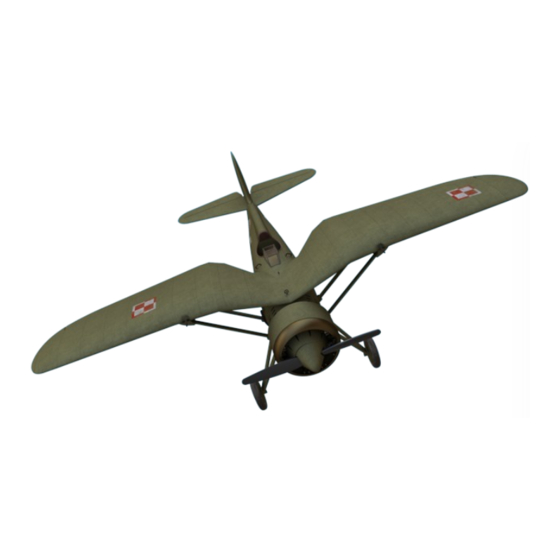
Page 2: Model Specification
member of Group ASSEMBLY INSTRUCTION FOR RC MODEL PRINTED ON 3D PRINTER Visit our website www.print-beat.com and purchase a product which you are interested in. Then you get an access for the file download in g-code or STL format. Download the files onto SD card. We try to optimize the universal G-code output for the widest selection of printers and we test our products on several printer brands and configurations. - Page 3 member of Group WHATEVER YOU NEED PLA filament for print model parts FLEX filament for print tire Super glue and Activator Spring diameter 7 mm 10x screws diameter 3mm 1x screws diameter 12mm Bowden wire 6x hinge Electric motor (recommended 3536 1300kv) Regulator Li-Po Battery 3s 2250mAh RC receaver...
- Page 4 member of Group PRINTED PARTS LIST No. Parts name Colour Weight Infil Suport E. Multiplier Perimeter Main Location 1 Fuselage Green 0,82 Fuselage_01_-_07 2 Fuselage Green 0,82 Fuselage_01_-_07 3 Fuselage Green 0,82 Fuselage_01_-_07 4 Fuselage Green 0,82 Fuselage_01_-_07 5 Fuselage Green Fuselage_01_-_07 6 Fuselage...
- Page 5 member of Group PRINTED PARTS LIST No. Parts name Colour Weight Infil Suport E. Multiplier Perimeter Main Location 37 Elevator Green 0,82 Elevator_37_-_48 38 Elevator Green 0,82 Elevator_37_-_48 39 Elevator Green 0,82 Elevator_37_-_48 40 Elevator Green 0,82 Elevator_37_-_48 41 Elevator Green 0,82 Elevator_37_-_48...
- Page 6 member of Group LANDING GEAR AND SUSPENSION The construction will start with the front lower part of the fuselage (5) to which the landing gear is attached.
- Page 7 member of Group LANDING GEAR AND SUSPENSION Glue the parts of the landing gear struts together (49-50) and then using M3 screw and M3 nut fix it to the the bottom part of the fuselage (5) Note: It is advisable to carefully fasten the nuts with glue so that the adhesive does not get into the thread, letting you to dismantle the assembly in the future.
- Page 8 member of Group LANDING GEAR STRUTS - SUSPENSION Landing Gear Suspension System: Insert the bowden cable (bent on the template) into the part (53) and secure it with a washer (54) and carefully glue it, then insert it into the opening at the bottom of the part (5).
- Page 9 member of Group LANDING WHEELS Landing Wheels and their parts : Insert a 25 mm long screw M3 into the housing (77) with the screw head towards the wheel disc (78) and put (part 77+screw) into the disk (78) and glue it. Then mount the tyre (79) onto the wheel disc (78) and attach the complete wheel to the chassis and secure the wheel with a nut M3 which you fix by Super Glue.
-
Page 10: Fuselage Assembly
member of Group FUSELAGE ASSEMBLY Assembly of the fuselage parts: by using the Super Glue cement together the fuselage parts (4-3-2-1). It is recommended to pull through the bowden cables for an increased accuracy. Now attach the fuselage part (6) and glue Landing gear fuselage part: Now attach the the pre-assembled landing gear unit (5) with the rest of the fuselage and do not... - Page 11 member of Group COCKPIT Cockpit: Complete the part of the fuselage number (4) where there is the cockpit with the details - the instrument panel (68), the headrest (73) and attach the handle (76). Then glue the windscreen (69) and check if the latch (72) fits into the opening and correctly to secure part (7)
- Page 12 member of Group Fin: Glue parts (56-57) and then attach them to the fuselage part (1), join the rudder parts (58-59) and insert the hinges that join these two parts which must remain movable. Attach the tail skid parts (64-65) to the rear fuselage part (1) Note: It is necessary to draw out the servo bowden wire and attach it to the rudder before you glue the parts of the rudder (59-58)
- Page 13 member of Group TAILPLANE Horizontal tailplane: into the fuselage part (1) cement the hexagonal pins (47), then glue tailplane parts (37- 38) and (41-42), which you attach to hexagonal pins and glue the whole together with the struts (48-49) to the fuselage (1) Elevators: join port (left) elevator parts (39-40) then starboard (right) parts (43-44-45), connect both parts together with the axle(46), make sure that the pieces are in plane, install the hinges in place and stick them into...
- Page 14 member of Group ENGINE PART - ELECTRIC MOTOR ATTACHMENT Engine part: Fit the electric motor holder (11) into the fuselage part (5) so that the Print Beat logo is properly legible, then adjust correct setting of the motor holder by insertion or removing according to the size of your electric motor (then fix it by Super Glue).
- Page 15 member of Group LEFT WING ASSEMBLY - SERVO Left Wing Assembly: start by connecting the middle part (7) with the first wing part (13), then prepare the parts 14-15. Note: Before connecting the part (15) install the servo and run the servo cable through the prepared hole.
- Page 16 member of Group WING ASSEMBLY - AILERON Aileron: Glue together the parts with the installed servo (14-15-16) into which you put the inner part of the aileron (23) fitted with a 0.9mm-1.2mm axle made from a bowden wire or paper clips, then install the outer part of the aileron (24) with the axle from each side and connect both parts of the ailerons so that the axle fits into the wing openings.
- Page 17 member of Group WING ASSEMBLY - COMPLETION Left Wing Assembly Completion: Put on the part number (17) onto the aileron axle and glue part (17) with the wing part (16). The completed wing assembly cement to part number (13), then to the assembled left wing attach the strut mounts (27-28).
-
Page 18: Wing Assembly
member of Group WING ASSEMBLY Right Wing Assembly: start by connecting the middle part (7) with the first wing part (18), then prepare the parts 19-20. Note: Before connecting the part (20) install the servo and run the servo cable through the prepared hole. Aileron: Glue together the parts with the installed servo (19-20-21) into which you put the inner part of the aileron (25) fitted with a 0.9mm-1.2mm axle made from a bowden wire or paper clips, then install the outer part of the aileron (26) with the axle from each side and connect both parts of the ailerons so that the axle fits into... - Page 19 member of Group TEMPLATE FOR THE LANDING GEAR SUSPENSION - SCALE 1/1 TEMPLATE FOR THE GLASS FRAME- SCALE 1/1...
Need help?
Do you have a question about the PRINT BEAT PZL p.11c and is the answer not in the manual?
Questions and answers