Advertisement
Table of Contents
- 1 Table of Contents
- 2 Ι. Safety Rules for Operation and Daily Maintenance of Forklift Truck
- 3 Ⅱ. Main Specifications of Forklift Truck
- 4 Ⅲ. Construction, Principle, Adjustment and Maintenance of Forklift Trucks
- 5 Transmission System
- 6 Brake System
- 7 Steering System
- 8 Electric System
- 9 Hydraulic System
- 10 Lifting System
- Download this manual
Advertisement
Table of Contents

Related Manuals for HELI G Series


Summary of Contents for HELI G Series
- Page 2 FOREWORD G series 1-3.5t lithium battery counterbalanced forklift truck is designed on the base of G series 1-3.5t battery counterbalanced forklift truck combined with lithium battery manage system. The truck has characters of environment friendliness, maintenance free, long service life, high efficient, energy saving, safety and it is suitable for low temperature.
-
Page 3: Table Of Contents
CONTENTS Ι. Safety Rules for Operation and Daily Maintenance of Forklift Truck ......1 Ⅱ. Main Specifications of Forklift Truck ................6 Ⅲ. Construction, Principle, Adjustment and Maintenance of Forklift Trucks ....14 1. Transmission System .................... 14 2. Brake System ......................19 3. -
Page 4: Ι. Safety Rules For Operation And Daily Maintenance Of Forklift Truck
Ι. Safety Rules for Operation and Daily Maintenance of Forklift Truck It is important that driver and manager for forklift trucks remember the principle of the “first safety” and ensure the safety operation as the description in 《OPERATION AND SERVICE MANUAL》&《OPERATION MANUAL》. 1.Delivery of Forklift Truck It must be pay attention to the following items when you deliver forklift trucks with container or trucks. - Page 5 (3)Check the devices of lighting, sound and alarm: check the lights, buzzer and horn (button on the handle included). (4) The forward-reverse lever should be in neutral. (5) Check all the levers and pedals. (6) Complete the provisions before starting. (7) Release the parking lever.
- Page 6 descending. (8) Pay attention to pedestrian, obstacle and bumpy road when driving. Pay attention to the clearance over forklift truck. (9) Never allow any persons to stand on the forks or the truck to carry persons. (10) Never permit anyone to stand or walk under upraised forks. (11) Don’t operate truck and attachment of it at any position out of the drive seat.
- Page 7 a) Hydraulic oil volume: oil level should stay in the middle of oil meter scale; b) Check piping, joints, pumps and valves for leaks or damages; c) Check service brake: The free travel of brake pedal should be within the range of 40mm; The clearance between the front floor and the pedal should be bigger than 20mm;...
-
Page 9: Ⅱ. Main Specifications Of Forklift Truck
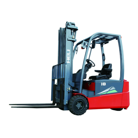
Ⅱ. Main Specifications of Forklift Truck Enternal view of forklift trucks... - Page 10 Main Specifications(1) CPD10 CPD15 CPD18 Model Unit GC1Li GC1Li GC1Li /GD1Li /GD1Li /GD1Li Rated capacity 1000 1500 1750 Load center Lifting height 3000 Free lifting height Mast tilt angle (fwd/bwd) ° (α/β) Fork size (T× W× L4) 32× 100× 770 35×...
- Page 11 Main Specifications(2) CPD20 CPD25 Model Unit GC1Li/GD1Li/GD3Li GC1Li/GD1Li/GD3Li Rated capacity 2000 2500 Load center Lifting height 3000 Free lifting height Mast tilt angle (fwd/bwd) ° (α/β) Fork size (T× W× L4) 40× 122× 920 40× 122× 1070 Wheelbase 1550 Tread (front/rear) (W3/W2) 960/950 Overall length (without forks)
- Page 12 Main Specifications(3) CPD30 CPD35 Model Unit GC1Li/GD1Li/GD3Li GC1Li/GD1Li/GD3Li Rated capacity 3000 3500 Load center Lifting height 3000 Free lifting height Mast tilt angle (fwd/bwd) (α/β) deg. 6/10 Fork size (T× W× L4) 45×125×1070 50×125×1070 Wheelbase 1685 Tread (front/rear ) W3/W2 1000/950 Overall length (without forks) L’...
- Page 13 Main Specifications(4) CPD30 CPD35 Model Unit GB3Li GB3Li Rated capacity 3000 3500 Load center Lifting height 3000 Free lifting height Mast tilt angle (fwd/bwd) (α/β) deg. 6/10 Fork size (T× W× L4) 45×125×1070 50×125×1070 Wheelbase L1 1715 Tread (front) W3 1000 Tread (rear) W2 Overall length (without forks) L’...
- Page 14 Main Specifications(5) CPD30 CPD35 Model Unit GB7Li GB7Li Rated capacity 3000 3500 Load center Lifting height 3000 Free lifting height Mast tilt angle (fwd/bwd) (α/β) deg. 6/10 Fork size (T× W× L4) 45×125×1070 50×125×1070 Wheelbase L1 1715 Tread (front) W3 1000 Tread (rear) W2 Overall length (without forks) L’...
- Page 15 Main Specifications(6) CPD30 CPD35 Model Unit GB2Li GB2Li Rated capacity 3000 3500 Load center Lifting height 3000 Free lifting height Mast tilt angle (fwd/bwd) (α/β) deg. 6/10 Fork size (T× W× L4) 45×125×1070 50×125×1070 Wheelbase L1 1715 Tread (front) W3 1000 Tread (rear) W2 Overall length (without forks) L’...
- Page 16 Main dismountable parts size and weight Mast (lifting height Counterweight Overhead guard 3000mm) Max. outline Weig Max. outline Weig Max. outline Weig dimension dimension dimension Model 300× 825× 10 1050× 1414× 1 1010× 480× 19 CPD10-GC1Li /GD1Li 300× 825× 10 1050×...
-
Page 17: Ⅲ. Construction, Principle, Adjustment And Maintenance Of Forklift Trucks
Ⅲ. Construction, Principle, Adjustment and Maintenance of Forklift Trucks 1. Transmission System 1.1 General description The transmission system consists of differential assembly and gearbox & axle assembly. With direct connection of the drive gear and the drive motor, the travel speed of the truck can be changed with the speed of the motor, and the travel direction can be changed with the rotation direction of the motor. - Page 18 1. Differential house 2. Planetary gear 3. Half axle gear 4. One-line axle 5. Half axle gear adjusting gasket 6. Duplex stopping locking plate 7. Bearing 8. Bolt 9. Pin 10. Gear ring Figure 1-2 differential assembly (3-3.5t) 1.3 Gearbox & axle assembly The gearbox &...
- Page 19 Truck model 1t,1.5t, 1.8t 2t,2.5t 3.5t Tyre size 6.0-9-10PR 6.0-9 23× 9-10-16PR 28× 9-15-14PR 28× 9-15 Rim size 4.00E 6.50F-10 7.00-15 Tyre pressure 860kPa Solid tyre 1030kPa 830kPa Solid tyre Fig. 1-3 Gearbox & axle assembly (1) Differential assembly (2) Main housing of the reducer casing (3) Spindle head assembly of the axle housing Ⅰ...
- Page 20 Fig. 1-4 Gearbox & axle assembly(1-1.8t,2t,2.5t) Figure 1-5 reducer and differential (3-3.5t)
- Page 21 1.4 Assembly of wheel hub (1) Fill the chamber of wheel hub with lubricating grease about 100cc, and then fit the hub on the housing. (2) Screw down the hub nut to a torque of 1kg.m, then loosen it for 1/2 turn.
-
Page 22: Brake System
2. Brake System 2.1 General description The brake system is the front two-wheel braking type consisting of brake pedal, master cylinder and service brakes. 2.1.1 Brake pedal The brake pedal is constructed as shown in figure 2-1.2 and mounted on the gearbox through a bracket. - Page 23 rod pushes the piston forward. The brake fluid in the cylinder flows back to the reserve tank through the return port until the primary cup blocks up the return port. After the primary cup passes through the return port, the brake fluid in the cylinder is pressurized and opens the check valve, flowing through the brake pipeline to the sub cylinder.
- Page 24 gearbox & axle assembly. The service brake is made up of two brake shoe, sub cylinder and adjuster. The brake shoe, one end of it being connected to the anchor pin and the other to the adjuster, is stressed on backing plate by the spring and spring pull rod. In addition, a parking brake and a clearance self-adjusting mechanism are fitted on the service brake.
- Page 25 The pull rod is mounted to the primary shoe side by pin. The move of the pull rod is transmitted to the secondary shoe side through push rod. (See Fig. 2-5) Fig. 2-5 Parking brake (3) Clearance self-adjusting mechanism A proper clearance between the friction piece and the brake drum is maintained by the clearance self-adjusting mechanism.
- Page 26 brake shoe and rotate together. Then the pulling rod turn right with point A as pivot and thus B point is raised up. See figure 2-6. When brake is released, the pulling rod turn left under the spring action and thus B point lowers. When the clearance between friction disc and brake drum increases, b rotating vertical dimension increases.
- Page 27 Fig. 2-8 Brake assembly (1) Braking cable ass’y (2) Washer 8 (3) Bolt M8× 20 (4) Ratchet pawl (5) Pin roll (6) Torsional spring (7) Parking push rod (8) Spring (9) Rear brake shoe with friction plate (10) Spring pull rod (11) Return spring for brake shoe (12) Guide pad (13) Guide plate...
- Page 28 The parking brake lever is of a ratchet type. Different brake force can be achieved on slope and ground. Brake force adjustment: When you turns the adjuster clockwise, the force increases, otherwise, when you turns the adjuster counter clockwise, the force decreases. (See Fig. 2-9) Pull force: 20 to 30kg.
- Page 29 2.2.1 Service brake disassembly Remove support pin, adjusting lever, adjusting device and spring of secondary shoe. (See Fig. 2-10) Fig. 2-10 (2) Remove two shoes return springs. (See Fig.2-11) Fig. 2-11 (3) Remove the hold-down springs. (See Fig. 2-12) Fig. 2-12 (4) Remove the primary and secondary shoes.
- Page 30 (5) Remove the brake line from the brake cylinder. Remove brake cylinder mounting bolts and detach the brake cylinder from the backing plate. (See Fig. 2-14) Fig. 2-14 Remove E-retainer securing the parking brake cable to the backing plate. Remove the backing plate mounting bolts and detach the backing plate from the axle.
- Page 31 (1) Check the operating cylinder inner surface and the piston periphery surface for rusting. Then, measure the clearance between the piston and cylinder. (See Fig.2-17) Fig. 2-17 Standard: 0.03-0.10mm Maximum clearance: 0.15mm (2) Visually check the piston cup for damage or deformation. If unsatisfactory, replace with new one.
- Page 32 2.2.3 Service brake reassembly (1) Apply brake fluid to the piston and the piston cup, and reinstall the spring, cup, the piston and the dust cover in this order. (2) Install the operating cylinder on the backing plate. (3) Install the backing plate on the front axle. (4) Apply heat-resisting grease on the points indicated in Fig.
- Page 33 (8) Install the shoe guide plate on the anchor pin, and install the shoe return spring. Install the main shoe first and then secondary shoe. (See Fig. 2-22) Fig. 2-22 (9) Install the adjuster, adjuster spring, push rod and its return spring. Pay attention to the following points: a) Adjuster thread direction and its mounting direction.
- Page 34 adjusting level with your finger along the arrow marks to turn the adjuster gear. When removing off your finger, the adjusting lever should return to its original position without rotation of the adjuster gear. Note: Even if the adjuster gear turn back along the adjusting lever motion when removing your finger, the adjuster will still operate normally after it is built in the machine.
- Page 35 (2) Adjust the stopper bolt and the height of the pedal. (See Fig. 2-26) (3) Press the brake pedal. Pull the push rod out until its front end comes into contact with the master cylinder piston. (4) Tighten the push rod locking nut. Fig.
- Page 36 b) Pull the plug out to let the lead separate. c) Turn the switch to make the clearance about 1mm. d) Make sure that when you press the Fig. 2-27 brake pedal the brake lamp light at the same time. ( See Fig.2-27) 2.2.6 Service brake troubleshooting (See Table 5) Table 5 Problem...
-
Page 37: Steering System
3. Steering System 3.1 General Description The function of steering system of forklift is to change the driving direction of the forklift or keep the forklift in straight line driving. The performance of steering system directly concerns with the driving safety, operation efficiency of forklifts and labor intensity of drivers. - Page 38 The difference between fully hydraulic and hydraulic power steering gears is the first substitutes the mechanical elements such as steering gear and longitudinal tie etc and has high pressure oil pipe connecting fully hydraulic steering gear with oil cylinder. The pressure-gradient control valve mounted in the loop of load- sensing and fully hydraulic steering system can ensure distribution of flow to steering system first and sufficient oil supply at any working conditions.
- Page 39 G-series forklift of 1.0~3.5t adopts cycloid rotary valve type fully hydraulic steering gear and it is a closed-type dynamic load steering gear. Refer to hydraulic system for details). (3) Transmission gear for steering The mechanism that deflects the right and left wheels according to a certain relation through oil cylinder and steering mechanism with power output by steering gear is called transmission gear and it is realized though horizontal style oil cylinder steering axle assemblies.
- Page 40 Figure 3-2 steering axle (1) steering knuckle main pin (2) needle bearing (3) thrust bearing (4) oil seal (5) Steering hub (6) tapered roller bearing (7) washer (8) lock nut (9) hub cover (10) tapered roller bearing (11) pin (12) steering knuckle (13) needle bearing (14) adjusting shim (15) oil seal...
- Page 41 Figure 3-3 Steering knuckle 1. thrust bearing 2. Steering knucle 3. Dust-proof cover 4. Steering knuckle main pin 5. needle bearing 6. Shock absorption blcok 2) Steering cylinder The steering cylinder is of double-action piston type. Both ends of the piston rod are connected with steering knuckles through connection rod.
- Page 42 (1) cylinder bore (2) supporting ring (3) cylinder cover (4) O ring (5) O ring (6) O ring (7) U ring (8) dust proof ring (9) retainer ring (10) piston rod assembly 3) Hub The hub is fixed to the steering knuckle shaft with two tapered roller bearing. The wheels are assembled on the hubs through rims.
- Page 43 Fig. 3-5 Fill lubricating grease and pre-load adjustment When changing the tires, the hub bolts should be coated with sealant after a new tire is mounted to ensure the tightening torque of the hub bolts is 160N.m for1~3.5t forklifts. 3.5.2 Maintenance and service of steering system (1) The steering king pin needs to be checked every 40 hours and grease be replenished to the bent neck type grease fittings of king pin every 300 hours, piston rod and link rod of steering oil cylinder, rotation connection parts of right and left knuckle...
-
Page 44: Electric System
CURTIS electric control system is G series 1-3.5t lithium battery forklift truck standard equipment which offers low noisy, high efficient, smooth and safe control. G series 1-3.5t lithium battery forklift truck electrical system offers a variety of brands to choose from. Currently, there are CURTIS, INMOTION, ZAPI and... - Page 45 efficient, smooth, unhindered and safe control. The electric system is composed of instrument, control system, traction motor, pump motor, battery pack, control switch, lighting and wiring harness etc.. Notice: Our Company has the right to improve on the production. Please contact with our company if there is any difference between the product and the manual.
- Page 46 Fig. 4-1 Circuit diagrams of electric system (CPD10~18-GC1Li)
- Page 47 Fig. 4-2 Circuit diagrams of electric system (CPD10~18-GD1Li)
- Page 48 Figure 4-3 Circuit diagrams of electric system(CPD10~18-GD3Li)...
- Page 49 Fig. 4-4 Circuit diagrams of electric system (CPD20~25-GC1Li)
- Page 50 Fig. 4-5 Circuit diagrams of electric system(CPD20~25-GD1Li)...
- Page 51 Figure 4-6 Circuit diagrams of electric system(CPD20~25-GD3Li)...
- Page 52 Fig. 4-7 Circuit diagrams of electric system CPD30~35-GC1Li)
- Page 53 Fig. 4-8 Circuit diagrams of electric system CPD30~35-GD1Li)
- Page 54 Figure 4-9 Circuit diagrams of electric system (CPD30~35-GD3Li)
- Page 55 Figure 4-10 Circuit diagrams of electric system (CPD30~35-GB7Li)
- Page 56 Figure 4-11 Circuit diagrams of electric system (CPD30~35-GB3Li)
- Page 57 F3- 1 0 A 1 2V + E m e r g e n c y S W . K e y S W . D C- DC F5- 15A 8 0V + 3 00 W 8 0V DC -1 2V DC 1 00 A NETWORKING DEVICE M a i n c o n t a c t o r...
- Page 58 4.2 Instrument 4.2.1 ENGAGE IV instrument (for Curtis controller) (1) Display of the instrument Fig. 4-13 Display of the CURTIS ENGAGE Ⅳ instrument 1)Forward indication light 2)Fault code of traction controller 3)Speed status indicator 4)Fault code of pump controller 5)Steering angle display 6)State of hand brake 7)Fault LED 8)Lift lockout display 9)Travelling mode indicator 10)Selection button 11)Selection button 12) Speed display 13)Battery capacity display 14)Menu buttn...
- Page 59 “ ”is back off indicator, high level trigger; “ ”indicates neutral, low level trigger; “ ”indicates parking brake, high level trigger; “ ” indicates lift locking, instrument control; “ ”indicates the travelling mode of the traction system is economic mode and the mode is the default setting. There are powerful mode “ ”...
- Page 60 Turn on the key switch, “HELI,LIFTING THE FUTURE”will be shown on the instrument when the power is on. Then instrument self check will be finished and battery...
- Page 61 shown on the instrument homepage. Figure 4-15 Instrument display interface of Jiacheng instrument (fault free condition) b) Battery dump energy: the figure of battery dump energy has 10 squares. When the battery is full, the 10 squares are on under power on condition. Then the squares will reduce with the discharging of battery.
- Page 62 Fig. 4-17 Panel layout of Songzheng instrument 4.2.3.2 Parameter specification of instrument (1)The instrument interface displays a tree diagram...
- Page 63 Long press the enter key 5S to enter the Main display interface menu from the main display interface 2.Monitoring 3.Start Screen 4.Type of drive 5.Type of pump 1.Parameter setup 6.Clock setup menu ON/OFF fault 1/2 control failure 1/2 2.2 Pump motor 2.1 Drive motor controller monitoring controller monitoring...
- Page 64 configured with this) ◆Clock setup: Through this parameter, the meter time can be set to the actual time. However, this time can be reset after the constant power failure of the meter. ◆Hourmeter reset to zero: This parameter can reset the hourmeter, hourmeter can only be the accumulated working time of the instrument;...
- Page 65 The display forms an interactive interface with the operator through the main page and many submenus. a) open the key switch, and after the meter is powered on, the words "HELI AC SYSTEM" will appear on the LCD screen to complete the self-check of the meter system.
- Page 66 Fig. 4-19 Display interface on the ZAPI instrument (no fault) b) Battery power display; The battery capacity (BDI) graph has a total of 20 grids. When the vehicle is energized and the battery is full, the graph is full grid (i.e., 20 grids). The battery discharge, then as the storage capacity of the battery decreases, the number of grid gradually decreases.
- Page 67 Table 4-2 ZAPI system CAN bus network information CAN bus network control module number Module information SICOS Traction-type Traction drive model Traction driven model Lift type EPS-AC MHYRIO Intelligent display 4.3 Controller 4.3.1 General description This series of balanced forklift can be equipped with four motor controllers, namely CURTIS motor controller imported from the United States, INMOTION motor controller imported from Sweden, ZAPI motor controller imported from Italy and SONGZHENG motor controller, an independent domestic brand.
- Page 68 4.3.2 CURTIS control device ; ; Fig.4-21 The controller of CPD10~18-GC1Li...
- Page 69 Fig.4-22 The controller of CPD10~18-GD1Li...
- Page 70 Fig.4-23 The controller of CPD10~18-G31Li...
- Page 71 Fig.4-24 The controller of CPD20~25-GC1Li...
- Page 72 Fig.4-25 The controller of CPD20~25-GD1Li...
- Page 73 Fig.4-26 The controller of CPD20~25-GD3Li...
- Page 74 Fig.4-27 The controller of CPD30~35-GC1Li...
- Page 75 Fig.4-28 The controller of CPD30~35-GD1Li...
- Page 76 Fig.4-29 The controller of CPD30~35-GD3Li...
- Page 77 Fig.4-30 The controller of CPD30~35-GB7Li...
- Page 78 Fig.4-31 The controller of CPD30~35-GB3Li...
- Page 79 Fig.4-32 The controller of CPD30~35-GB2Li Notice: The manufacturer will provide quality warranty for motor controller and the manufacturer will be informed in time for after sales service in case of fault. Please do not open it for maintenance without authorization of manufacturing. The users will be responsible for the personal and property losses caused by maintenance at their own will.
- Page 80 4.4 Motor 4.4.1 Specifications of motors Table 4-3 Specifications of motors Model CPD30~ CPD20~ CPD10~ CPD18-G CPD10~ CPD20~ CPD30~ GDLi/GD 18-GD1L C1Li 15-GC1Li 25-GC1Li GD1Li/GD 35-GCLi 3Li/GB3L Item i/GB7Li/G B2Li Travelling TSW180/ YDQ8.2- YDQ8-4-61 YDQ8-4- YDQ11.5-4 YDQ11.5-4 TSP180/4- motor 4-200LT6 4-6190 6190 -6190...
- Page 81 (1) Daily check a) Insulated resistance. Limit value (≥1 M) b) Rotor should running agilely without touch. c) Check up the motor connection whether exact and firm. d) Check up between commutating piece of commutator whether clean. Notice: During maintenance, the oil contamination on the commutator should be wiped clean by lint free cloth dipped in alcohol and electric brush powder between commutators should be clean up with hairbrush.
- Page 82 left during polishing. b) After polishing brush with emery cloth and cleanup the commutator, the motor should running with limit speed to assure safety, until the working surface of brush polished. (3) Working environment a) Not higher than 1200m altitude. b) Temperature between -25º...
- Page 83 If there is any question, please contact with HELI technical department or after sale service department.
- Page 84 (3) Improper using of the product may lead to battery cell ballooning which may even cause plastic housing broken or crack. If occurs, stop using the truck at once and contact with HELI technical department or after sale service department. (4) It is prohibited to disassemble, press, impale, storing under high temerature or firing battery case to prevent the battery from high strength shaking, external impact force and falling down.
- Page 85 (12) It is prohibited to make the lithium battery protective circuit board or battery management system power system in series or parallel with other system. The operation may lead on injuries or property loss. If necessary, contact with HELI technical department or after sale service department.
- Page 86 the battery is well. (8) If the battery leaks (liquid or smoke) or is damaged, please go to the safe place and contact with after sale service person. (9) If the electrolyte leaks, do not touch it. If it is touched accidently, wash with plenty of water at once.
- Page 87 4.5.3 Charger type Item Note D80V-200A-Li lithium battery fast charger 80V/48V compatibility D80V-200A-Li-423 lithium battery fast charger D48V-200A-Li lithium battery fast charger D48V-200A-Li-423 lithium battery fast charger 4.5.4 Charger using notes (1) Charge the battery in a safe environment where is away from dust, fire source and corrosion.
- Page 88 opening cover. b) Do not pull the or twist charging cable. c) The charging equipment should not bear shock. d) Do not store or use the charging equipment when the temperature is higher than 50℃. e) It is prohibited to disconnect the changer when there is current output or electric arc may be produced which will cause person injury or property loss.
- Page 89 (1) Check the wear condition of the contactor. Change it if necessary. Check the contactor every three months. (2) Check the pedals or manual inching switch; measure the voltage drop between the inching switch ends; there is no resistance when the inching switch is closed; there is ringing sound when release.
- Page 90 Table 4-5 Fault code and troubleshooting of 1236/1238 series controllers Code Programmer LCD display Possible cause Set/Clear conditions External short of phase U, V or W Phase current exceeded motor connections. Controller Overcurrent the current Motor parameters are mis-tuned. measurement limit. Controller defective.
- Page 91 Battery disconnected while regen braking. 5V supply (pin 26) 5V Supply Failure 5V supply overload. outside the 5V±10% range. Digital Output 6 Digtial Out 6 Overcurrent Digital Output 6 overcurrent. (pin19) current exceeded 15mA. Digital Output 7 Digtial Out 7 Overcurrent Digital Output 7 overcurrent.
- Page 92 threshold. Pot2 Wiper High Throttle pot2 wiper voltage too high. Replace throttle 2. Bring throttle pot2 Throttle pot2 wiper (pin17) voltage is wiper (pin17) voltage Pot2 Wiper Low lower than set value. above the fault threshold. Pot low (pin18) current exceeds Pot Low Overcurrent Check pot low.
- Page 93 state. Motor parameter out of the range of controller. Motor type is out of OS system. Select correct motor Motor Type Fault type, cycle KSI. The VCL software in the controller Download the correct VCL/OS Mismatch doesn’t match the OS software in the VCL and OS software controller.
- Page 94 2) “CONTACT CNTRL” setting is not correct. 3) Main contactor driver shorted. 1) Precharge circuit failure. ¤ ¤ ¤ ¤ ¤ ¤ PRECHARGE FAULT 2) External short or leakage between B+ and B-. 1) Main contactor coil connection loose. ¤ ¤ ¤ ¤ ¤ ¤ ¤ MAIN CONT DNC 2) Main contactor did not close.
- Page 95 ERROR: steering angle analog quantity exceeds steering angle analog quantity is range. damaged or recalibrate analog quality Alarm of high truck speed WARNING of traction driver speed protection Check if encoder harness is poor WARNING: fault of traction driver encoder connected.
- Page 96 Change driver ERROR pump driver temperature sensor failure Overlow environment temperature WARNING: low pump motor temperature Pump motor temperature is overhigh and WARNING: high pump motor temperature its power is limited. Pump motor temperature sensor is ERROR: pump motor temperature sensor failure abnormal and please check sensor or harness.
- Page 97 BMS cut output current and please check BMS current cutout protection battery. Please check CAN, controller and BMS communication error battery. 4.8.3 SONGZHENG control system Tab. 4-8 Fault code and treatment of SONGZHENG controller Fault generation Fault Fault exit condition Troubleshooting condition Disconnect...
- Page 98 value + battery voltage 1-7 failure code power reduction range) Limit maximum current Power voltage output Power voltage≥configured <( configured controller Overvoltage overvoltage +2V) ± overvoltage ±2V proportionally; 2. The fault indicator light report 2-4 fault code Power voltage ≥ serious controller 1.
- Page 99 or > configured maximum configured minimum current value and ≤ current value configured maximum current value 1. Equivalent output accelerator of accelerator is 0; connected or the output High accelerator Properly connected 2.The failure output voltage of the accelerator≥ accelerator indicator light report 5.5V 4—1 fault code...
- Page 100 1—1 fault code 1.The controller MCU failed does not output; failed Restart the key 2.The failure communication communication with DSP indicator light report with DSP 2—1 fault code Lithium battery total Total pressure is The lithium battery The controller does pressure high, too high...
- Page 101 controller detects that the key startup of the key switch, it hole input voltage is too low. For may be caused by external 36/48v controller, the load, such as dc-dc startup, low-voltage critical value is 11V. relay, solenoid valve switching For an 80V controller, the low on and off, etc.
- Page 102 alternately, and expect phase resistance); voltage can be equated to the (2) whether the motor wire is cathode voltage, if one phase well connected; voltage is higher than 10% of the (3) if there is no external nominal battery voltage (80 v problem and the motor wire is system, rated voltage of 80 v), well connected, the problem...
-
Page 103: Hydraulic System
capacitor voltage is lower than 2. It may be that PTC or 20% of the rated voltage within charging resistance is the specified time, this fault will disconnected, or there is a occur problem in the controller, and the controller needs to be replaced The temperature of the controller is higher than 85 °... - Page 104 Fig 5-1 Working principle of gear pump (1) Oil suction cavity (2) Oil pressing cavity A pair of meshed involute gear is mounted inside the housing, the two end face seals of gear and gear separate the pump housing into two sealing oil cavities as shown 1 and 2 in the Fig.
- Page 105 Fig. 5-2 Main pump (1) Pump body (2) Driving gear (3) Driven gear (4) Front cover (5) Rear cover (6) Lining plate (7) Seal ring (8) Ring (9) Oil seal (10) Snap ring 5.1.2 Control Valve The external of the control valve as shown in Fig. 5-3.
- Page 106 Fig. 5-3 Control valve The control valve adopts two pieces and four body type. The hydraulic oil from working pump distributes the high-pressure oil to the lifting cylinder or tilting cylinder through the control of valve stem. There are safety relief and tilt-locking valves inside the control valve.
- Page 107 (1) Spool operation (take the tilt spool valve for example) a) Neutral position (See Fig. 5-4) The high-pressure oil from lift pump returns to the oil tank through the mid-passage. Fig. 5-4 Neutral position b) Pushing-in of spool (See Fig. 5-5) In this time, the spool is pushed in to close the mid-passage.
- Page 108 The relief valve is mounted between “HP” nozzle of oil pump and “LP” passage. Oil passing through lifting valve C acts on different areas of diameters “A” and “B”, thus, “K” of check valve and “D” of overflow lift valve are on the valve seat as shown in Fig. 5-7.
- Page 109 (3) Action of tilt-lock valve Tilt spool valve housing contains a tilt-lock valve. The tilt lock valve is intended to prevent vibrations of the mast resulting from the negative pressure in the tilt cylinder and also to avoid danger incurred from mishandling of the spool. When the lift motor isn’t running, the mast doesn’t be tilted forward by push the tilt lever.
- Page 110 Fig. 5-13 Operation of the control valve As you see in Fig. 5-14, the mast lift up when you push the lift lever forward, the mast fall down when you pull the lift lever backward. The mast tilt forward when you push the tilt lever forward, the mast tilt backward when you pull the tilt lever backward.
- Page 111 The pressure of the safety valve shall not be adjusted by non-professional personnel. The adjustment shall follow following procedures: a) Screw off the plug of the measuring hole on the inlet of the control valve. Install an oil pressure gauge capable of measuring 25MPa. b) Operate tilting lever and measure the pressure at the end of the cylinder stroke.
- Page 112 Fig. 5-16 Lift cylinder 1. Bolt M16×1.5×40 2.washer 16 3.chain wheel 4. Snap ring 40 5. Chain wheel assembly 6.spacer bush 7. Bolt M12×1.25×25 8. Bolt M12×1.25×50 9.U type bolt 10.Nut M10×1.25 11.waher 10 12.washer 10 13. Pin B10×26 14. Adjusting block 15.Oil cylinder support block 16.
- Page 113 5.1.4 Cut-off valve The cutoff valve is mounted at the bottom of the hoist cylinder (See Fig. 5-17) to prevent the goods from falling suddenly when the high pressure pipe is broken. The oil from hoist cylinder passes through the hole A on the outer circumference of the spool when returning to oil tank, if flow rate of oil through the hole is less than the setting value of the valve and the pressure difference before and after spool smaller than spring force, the spool will not move at this time and slide valve does not work.
- Page 114 When the lift spool is placed in the “lift” position, the oil from the control valve flows through the oil chambers A and B, oil holes C, D, E and F, and the chamber G to the lift cylinder without any regulation. When the lift spool is placed in the “down” position, the oil pusses the orifice plate and a pressure difference generates between the chambers A and B, the pressure difference overcomes the force of the spring and moves the valve core right, thus the oil flow being decreased by narrowing of the hole D and C,...
- Page 115 Yx-ring and O-ring to prevent oil leakage and keep dust off. Fitted with them, the guide sleeve is screwed into the cylinder body. When piston moves, oil enters from one port and exits from the other. The piston rod is furnished with adjusting threads to adjust the difference between the dip angles.
- Page 116 Fig. 5-20 Hydraulic system principle diagram (1) Oil tank (2) Oil suction filter (3) Pump motor (4) Gear pump (5) Steering unit (6) Steering cylinder (7) Control valve (8) Flow regulator valve (9) Cut-off valve (10) Lift cylinder (11) Tilt cylinder (12) Return oil filter...
- Page 117 Fig. 5-21 hydraulic oil circuit 5.2 Maintenance,Fault Analysis and Remedies 5.2.1 Maintenance Check if there is any seepage and serious oil leakage on the pipe fittings of hydraulic drive system, hoist cylinder, tilt cylinder, oil pump, fully hydraulic steering gear and steering cylinder before and after each shift.
- Page 118 c) Remove lining plate 6, drive gear2, driven gear 3. d) Remove the seal ring 7 and ring 8 from front cover or rear cover. Notice: Don’t remove the seal ring and ring from the front cover and rear cover, if the seal ring and ring needn’t be replaced.
- Page 119 2) Inspection Check the disassembled parts and wash them with gasoline (except rubber parts) a) Body inspection (See Fig. 5-23) If the contact length between pump body lumen and gear longer than 1/2 long of the perimeter, replace the pump body. Fig.
- Page 120 e) Replace seal rings, bushings, seal rings, rings, oil seals and snap rings as required. Fig. 5-27 (3) Reassembly a) Fixed the front cover on the clamping. (See Fig. 5-28) Fig. 5-28 b) Install a new seal ring on the front cover of the pump.
- Page 121 f) Install the drive gearon the pump body with the side of the spline downward. Fig. 5-33 g) Install the driven gear on the pump body as the direction shown in Fig. 5-34. Fig. 5-34 Install the lining plate on the side of the gear, don’t confuse the inlet oil port and the outlet oil port.
- Page 122 l) Take down the pump from the clamping. Apply lubricating grease on the outside circle and lip of the oil seal, install Fig. 5-39 it on the front cover with mould. m) Install the snap ring with callipers, fixed the oil seal. Fig.
- Page 123 of the pump’s surface increases to a over high degree, reduce the load and lower the oil temperature. And then go on carrying on the trail. e) Make the relieving pressure at 210kg/ cm after the test and measure the flowl. Measure the oil lever through the lifting speed.
-
Page 124: Lifting System
YX-ring seal and O-ring seal in the pilot sleeve. 1) Select appropriate oil pump or check 1) Insufficient oil supply of oil pump, to see if the oil pump is normal. the slow-steering hand wheel feels relatively light and the fast-steering hand wheel heavy. - Page 125 The maintenance of the roller and the side rollers on the inner and outer masts belong to exalted maintenance. Please be careful. 6.3 Lift Bracket The lift bracket moves up and down smoothly along the channel of the inner mast with main rollers.
- Page 126 Fig. 6-1 Layout of the rollers Fig. 6-2 Adjusting method and request of the main and side rollers...
- Page 127 Fig. 6-3 Adjusting method and request of the second roller of the lift bracket Fig. 6-4 Additional remarks for the roller adjusting of the lift bracket 6.5 Maintenance 6.5.1 Adjust lift cylinder It must readjust stroke of the lift cylinder when the lift cylinder, the inner mast or the outer mast is replaced.
- Page 128 (1) Place piston rod heads into the upper beam of the inner mast without shims. (2) Ensure that two lift cylinders are lifted at the same time when the mast ascended the ultimately stroke. (3) If they not lifted synchronously, add shims between the upper beam of the inner mast and the piston rod head which reaches the lift cylinder’s ultimately stroke in movement.
- Page 129 Fig. 6-6 Adjust lift bracket’s height 6.5.3 Replacing rollers of the lift bracket (1) Place a salver on the forks and make the forklift stop on the horizontal ground. (2) Make the forks and salver descend to the ground. (3) Take down tie-in on top of the chains. And take out chains from sheave. (See Fig. 6-7) (4) Make the inner mast rise.
- Page 130 (1) Take apart the fork bracket from the inner mast, then replace the main roller follows the way as 6.5.3. (2) Park the truck on the horizontal ground and lift up the front-wheel 250~300mm from the ground. (3) Pull parking brake level fully, and use a wedge to make back-wheel stationary. (4) Take apart bolts which fastened lift cylinders and the inner mast.
Need help?
Do you have a question about the G Series and is the answer not in the manual?
Questions and answers
Bms current alarm cut off
The BMS current alarm cut-off for HELI G Series is indicated by fault code 169, which is "BMS current cutout protection." This means the BMS has cut output current, and the battery should be checked.
This answer is automatically generated