HELI gleen Series Operation & Service Manual
1.5 ton stand type reach trucks
Hide thumbs
Also See for gleen Series:
- Operation & service manual (77 pages) ,
- Operation & service manual (67 pages)
Table of Contents
Advertisement
Quick Links
Advertisement
Table of Contents

Related Manuals for HELI gleen Series


Summary of Contents for HELI gleen Series
-
Page 2: Table Of Contents
CONTENT Ⅰ. Safety Instructions of Operation and Driving……………………1 Ⅱ.External View of Stand Type Reach Trucks ………………………4 Ⅲ. Main Specifications…………………………………………………5 Ⅳ. Structure and Principle of Reach Trucks…………………………6 ……………………………………………………6 1. Transmission system …………………………………………………………10 2. Steering system …………………………………………………………14 3. Braking system ………………………………………………………19 4. Hydraulic system …………………………………………………………28 5. -
Page 3: Ⅰ. Safety Instructions Of Operation And Driving
Ⅰ. Safety Instructions of Operation and Driving 1. The driver and managing personnel of the truck must keep firmly in mind “Safety First” and carry out safety and standardized operation according to the Operation & Service Manual and Operator’s Manual for the truck. 2. - Page 4 5. Operation of the truck (1) Pay attention to the state of mechanical, hydraulic and electrical system. (2) Turn on the power, first turn on the key switch, press down the brake pedal ( it is in non-braking state when the pedal is pressed down), operate the acceleration handle (this handle has the functions of direction switch and accelerator) and keep proper starting acceleration .
- Page 5 6. Battery charging (1) Strictly obey the stipulations in operation instruction for battery when first charging or recharging. (2) If the output voltage of the battery is reduced to 41V or the voltage of anyone lower than 1.7V or the red lamp on the instrument board lights up, the truck should stop working immediately until the battery is replaced or charged.
-
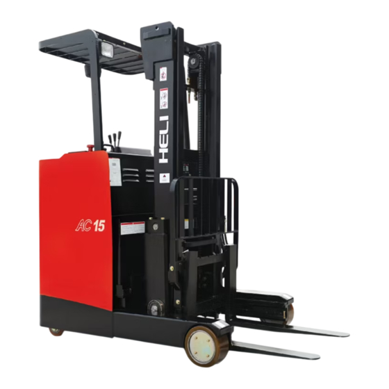
Page 6: Ⅱ.external View Of Stand Type Reach Trucks
Ⅱ.External View of Stand Type Reach Trucks Fig.1 External view of stand type reach trucks... -
Page 7: Ⅲ. Main Specifications
Ⅲ. Main Specifications Unit CQD15-GA2R Load capacity 1500 Load center Standard lifting height 3100 Free lifting height Fork size (length×width×thickness) 920×122×40 ° Mast tilt angle (F/R) Max. lifting speed (unladen/laden) mm/s 0.4/0.26 Max. travel speed (unladen/laden) km/h 9.5/8.5 Gradeability (unladen/laden) 12.5/10 Wheelbase 1356... -
Page 8: Ⅳ. Structure And Principle Of Reach Trucks
Ⅳ. Structure and Principle of Reach Trucks 1. Transmission system Type Three stage deceleration Name Driving unit Speed reduction ratio 17.96 Volume of oil 3.7L φ 330×114 Tyre size, drive wheel The driving unit of the standing type reach truck is mainly mechanical transmission case. - Page 9 EPS motor Drive motor Upper housing Oil seal EPS transmission unit Gear Middle housing Lower housing Bevel gear shaft Drive shaft Bevel gear shaft Oil seal Fig.2 Driving unit (d) Turn the bolt in the wheel hub center into an installation bolt for driving wheel.
- Page 10 Change the bolt A into the installation bolt of driving wheel Installation bolt Bolt A Stop the wheel Make this side (left and right backward sides) Fig.3 Dismantle driving wheels (2) Install driving wheel (refer to Fig.4) Bolt A Tightening torque : 650-900 kg.cm Coat 262#...
- Page 11 (e) Turn the steering wheel to return the driving wheel to the straight-forward state. (f) Remove the pad. 1.2.2 Meshing of the bevel gear shaft and bevel gear and the adjustment of the side clearance (1) Put the driving shaft and bevel gear in the housing after the adjustment pad being put in.
-
Page 12: Steering System
2. Steering system Type Driving unit rotary type, electronic power steering Steering motor 500W 2300rpm Steering reduction ratio EPS driving unit speed ratio 25.83 Control mode φ 200 Steering wheel diameter The steering system of the standing type reach truck is mainly composed of steering wheel, direction sensor, steering motor, steering speed reducer, electric steering controller, etc. - Page 13 EPS motor Upper housing Gear A Gear C Gear B Oil seal Gear D Fig.6 EPS transmission unit To prevent this from happening, the counterforce of the spring shall be used on the driving unit in the direction contrary to the caster movement to compensate the wheel pressure as shown in Fig.7.
- Page 14 2.1.3 Casters (as shown in Fig.8) As part of the rear axle, the casters shall rotate along with the truck traveling direction at steering. The casters are connected on the frame by pins. The movement of the link rod shall be transmitted to the rear axle through springs. The knuckle spindle is installed on the caster link rod by two tapered roller 50% of bearings.
- Page 15 Cover Wheel Stop assembly wheel (both sides of right and left) Fig.9 Dismantling casters 2.2.2 Press down the casters Use oil press to press down the hub from the wheel (refer to Fig.10) Oil press Wheel Fig.10 Press down casters 2.2.3 Assembling casters Press the hub in the wheel with oil press (refer to Fig.11).
-
Page 16: Braking System
2.2.4 Installation of casters (refer to Fig.12) (1) Install the wheel assembly on the shaft. (2) Put in gaskets and locking gaskets and tighten them with nuts. (3) Lock the nuts with the tooth of the locking gaskets. (4) Install the covers. Castor assembly Locking gasket Gasket... - Page 17 The braking caliper assembly is shown in Fig.13. The installation of the braking caliper is shown in Fig.14. Brake spring Pull rod Adjusting screw (upper) Lining Pull rod Adjusting screw Lining (lower ) Fig.13 Braking caliper assembly Braking disc Driving motor Brake assembly Fig14 Installation of braking caliper...
- Page 18 3.1.2 Braking pedal The installation of the braking pedal is shown in Fig.15. When the pedal is not pressed down, it shall turn up by the spring force. When it is pressed down, the action shall be transmitted to the cam rod of the braking caliper through the pull rod, crank-arm and link rod.
- Page 19 (3) After adjustment, install the spherical hinge and lock it with the locking nut. Spherical hinge Link rod Fig.16 Adjustment of pedal height 3.2.2 Adjustment of braking clearance and braking force (1) Adjustment of the braking clearance (refer to Fig.17) (a) Press the pedal down to the bottom and keep the position.
- Page 20 Fig.18 Adjustment of the braking force 3.2.3 Replacement of the linings (refer to Fig.19) (1) Turn the adjusting screw to the right. The clearance between the linings and braking disc shall be smaller. (2) Dismantle the installation bolts and linings. (3) Use the adjusting screw to enlarge the clearance between the pull rod and braking disc.
-
Page 21: Hydraulic System
Adjusting device Installation bolt Fig.20 Adjustment of the braking switch 4. Hydraulic system Model CBT-F412.5-AFH Type Gear pump Main oil pump Displacement 12.5 ml/r Output pressure 200 bar Maximum pressure 250 bar With overflow valve tilt Type self-locking valve Multi-way valve Adjusting pressure 145 bar Type... - Page 22 Cover Fig.21 Hydraulic oil tank 4.1.3 Multi-way reversing valve ( as shown in Fig. 22) The multi-way reversing valve consists of three plunger valve plates, one respectively for oil inlet and outlet with overflow valve which are connected by three bolts.
- Page 23 Tilt valve spindle Reach valve spindle Lifting valve spindle Overflow valve Potentiometer Fig.22 Multi-way reversing valve 4.1.4 Control device of multi-way reversing valve The valve spindle of the multi-way reversing valve is connected with operation lever as shown in Fig.23. Each operation lever is connected with a shaft and the valve assembly is mounted on the bracket.
- Page 24 Valve switch Potentiometer Fig.23 Control device of multi-way reversing valve 4.1.5 Lifting cylinder The structure of the lifting cylinder is as shown in Fig.24. ◆ The Service condition of the shutoff valve The hydraulic oil in the hydraulic cylinder shall pass through holes A and B on spool when returning to the oil tank and the spool shall not move if the flow speed of the hydraulic oil while passing though the hole is smaller than the setting value and the pressure difference before and after the spool is smaller than the spring force.
- Page 25 Fig.24 Lifting cylinder (1) Dust ring (2)U-ring (3) Screw (4) Gasket (5)O-ring (6) Cylinder cover (7) Cylinder body (left) (8)Snap ring (9) Piston rod (10) Pivot ring (11) Spool (12) Spring (13) Valve sleeve (14) Spring seat (15) O-ring (16) Valve seat (17) Cylinder body (right) (18) Adjusting shim...
- Page 26 Piston Spring Fig.25 The Service condition of the shutoff valve ( When the flow is smaller than the setting value) Body Fig.26 The Service condition of the shutoff valve ( When the flow is bigger than setting value) 4.1.6 Speed-limit valve The speed limit valve controls the descending speed of the forks and plays the role of security in case of accidental high pressure pipe breaking.
- Page 27 become slow. To lift the fork, the high pressure oil from multi-way valve enters into lifting cylinder through A、 B、C、D、E、F and G. Fig.27 Speed limit valve (1) Valve body (2) Spring (3) Steel ball (4) Spool (5) Valve sleeve (6) Flexible clip (7) Spring (8)O-ring (9) End cover 4.1.7 Tilt cylinder The structure of the tilt cylinder is shown in Fig.28.
- Page 28 Fig.28 Tilt cylinder (1) Earring (2)Snap ring (3) Knuckle bearing (4) Stop washer (5) Round nut (6) Piston rod assembly (7) Dust ring (8) Flapper (9)U-ring (10) Guide sleeve (11)O-ring (12) Steel-backed bearing (13) Cylinder assembly (14) Pivot ring (15) Flapper (16) U-ring (17) Steel-backed bearing...
- Page 29 Fig.29 Reach cylinder (1) Earring (2)Snap ring (3) Knuckle bearing (4) Stop washer (5) Round nut (6) Piston rod assembly (7) Dust ring (8)O-ring (9) Shaft used seal ring (10) Guide sleeve (11) Cylinder assembly (12) Hole used seal ring (13) Pivot ring...
-
Page 30: Lifting System
5. Lifting system 5.1 General description The lifting system is a two-stage telescopic rolling gantry, the inner gantry has ―I‖ end face and outer gantry has ―C‖ type welding reinforced end face, the fork and fork frame conform to the international standard and has about 140 mm free lifting during operation. -
Page 31: Support Wheel
Main roller Φ 78.3 Roller: Side roller Φ 40 Lifting chain: LH1244 The lifting system of fork mast: Hydraulic type The fork spacing adjustment device: Manual type The two section of standard type lifting system mainly consists of mast assembly, mast support, lifting cylinder, reach cylinder and side-shift cylinder etc. -
Page 32: Electric System
7. Electric system 7.1 General description The standard configuration of the electric system of CQD15-GA2R A.C standing type reach truck is a high performance all A.C control system and can realize the silence, high performance, smooth and safety control of the whole truck. The electric system mainly consists of smart instrument, traction control system, lifting control system, steering control system, storage battery, lighting system (optional), back-up buzzer set(optional) and wiring harness etc. - Page 33 Fig.7-1 Electrical circuit diagram...
- Page 34 7.2 Detail introduction 7.2.1 CAN-BUS line Using CAN-BUS link, every module connected to can net can act as the ―access node‖ to the canbus net for the external world. For example the ZAPI handy console (or the PC-Win console) can be physically connected to one module and , by the canbus, virtually connected to any other module of the net.
- Page 35 7.2.2.3 Operation instruction of instruments (1) Turn on the key switch and energize the instrument, the ―HELI AC SYSTEM‖ appears on the liquid crystal display screen. When the self-inspection of the instrument is finished, the main page displays the electric quantity of the battery, speed of truck and traction hour counter.
- Page 36 (3) Safety and braking indication: when the brake pedal is released, the whole truck is in braking state and it can not travel at this moment, but can change direction, lifting, forward and backward movement, inclining. The graph of the instrument normally on.
- Page 37 Trouble code Control module number Fig.7-6 7.2.2.4 Working environment (1) Not higher than 1200 meters altitude. (2) Temperature between -25℃ and +40℃. (3) Relative humidity not larger than 95%. 7.3 Introduction of controllers This AC stand-on reach truck is equipped with two ZAPI controllers. They control the truck’s traction, hoist system and steering system separately.
- Page 38 Fig.7-8 Steering controller 7.3.1 Traction and pump motor controllers Model of the traction motor controller: ZAPI COMBIAC2 48V/320A (1) COMBIAC2 controller is inverter for pairs of AC asynchronous 3-phase motor. It controls the traction and pump motor. It has regenerative braking functions, can-bus interface and digital control based upon a microcontroller (one per each motor).
- Page 39 c) Detailed fault detection and consultation for traction and lifting control system to facilitate the system maintenance. 7.3.2 Steering motor controller CQD15—GA2R A.C standing reach truck adopts advanced electronic power steering control system and is furnished with Italy imported EPS-ACO controller. Model of the steering motor controller: ZAPI EPS-ACO 48V/45A (1) EPS-AC0 controller adopts high frequency MOS technology and can realize the high efficiency, low consumption, and smooth and silence control while raising the...
- Page 40 system to facilitate the system maintenance. Attention: (1) After the chopper is mounted, uplift the wheel (off the ground) and make a test. In this case no danger shall appear even if there is a connection mistake. (2) After the electric lock switch is turned off, some voltage still remains in the filtration capacitance for a period of time.
- Page 41 7.5 Battery 7.5.1 Construction and standard Batteries are made of negative plate, positive plate, clapboard, cell cover and electrolyte. Model DA320 Capacity 320Ah/5 Voltage Density of the electrolyte 1.280-1.290g/cm (25℃) No. of the cell Fig.7-9 Construction of the battery Remarks: The imported storage battery can be provided according to the requirements of users.
- Page 42 the short circuit. (3) The first charging of the new storage battery before use is the initial charge and all the charges in the course of use are the common ones, the charging time of which are different according to the battery volume and discharging degree. Usually continuous charging about 8-12 hours for 70%~100% discharging .
- Page 43 ventilated, and the temperature stays between 5-40℃. (2) The batteries should not be exposed to direct shining or scorching sunlight or drench ingrain. The batteries should be kept off any heat source at least at a distance of two meters. (3) The batteries should not be placed, upside down or side or tossed or rolled, nor pressed heavily.
- Page 44 connection of the protective earthing line of the charger should be ensured to prevent the electric shock accident. (4) The battery connector assemblies should not be pulled out in case that the charger has not been turned off. Because it shall make the battery insufficiently charged and produce dangerous spark, therefore, take special care.
- Page 45 Faults Characteristic Causation Repair measure (1)The voltage (1)The plate curve, (1)Renew clapboard. battery is very low reactive matter expand (2)Offload during charging, close or desquamate, so the precipitate to zero indeed. clapboard mangled, conducting matter. (2)Few or none air that the battery short (3)Renew plate.
- Page 46 7.7 Faults diagnosis 7.7.1 Description The microcontrollers used on this truck continually monitor the inverter and carry out a diagnostic procedure on the main functions. The diagnosis is made in 4 points. (1) Diagnosis on key switch closing that checks: watchdog circuit, current sensor, capacitor charging, phase’s voltages, contactor drivers, can-bus interface, if the switch sequence for operation is correct and if the output of accelerator unit is correct, correct synchronization of the two μ...
- Page 47 7.7.2 Fault codes of COMBIAC2 inverter diagnostic Condition that has to ALARM CONTROLLER DESCRIPTION occur to come out from STRING STATUS alarm status × × × × × WATCH- Alarm: -If the alarm is present in Watchdog Init status, remove the circuit has been alarm condition triggered...
- Page 48 Condition that has to ALARM CONTROLLER DESCRIPTION occur to come out from STRING STATUS alarm status × × × × STBY I Alarm: wrong -If the alarm is present in HIGH voltage in the Init status, remove the current sensor alarm condition feedback circuit -If the alarm has occurred...
- Page 49 Condition that has to ALARM CONTROLLER DESCRIPTION occur to come out from STRING STATUS alarm status × × × × COIL Alarm: -If the alarm is present in SHORTED -Init: Init status, remove the coil alarm cause driver - If the alarm has occurred protection in stby or running mode, it circuit...
- Page 50 Condition that has to ALARM CONTROLLER DESCRIPTION occur to come out from STRING STATUS alarm status × × × × PUMP KO Alarm: Traction To recycle the key μ C detects a μ Pump malfunctioning × × × × MASTER Alarm: Pumpμ...
- Page 51 Condition that has to ALARM CONTROLLER DESCRIPTION occur to come out from STRING STATUS alarm status × × × × × HIGH Warning: To remove Warning cause TEMPE- Traction RATURE Pump or both temperature higher than 75℃ × × × ×...
- Page 52 Condition that has to ALARM CONTROLLER DESCRIPTION occur to come out from STRING STATUS alarm status × × × × × THERMIC Warning: To remove Warning cause SENSOR Traction Pump temperature sensor is out of range × × × × WAITING Warning: To remove Warning cause...
- Page 53 Condition that has to ALARM CONTROLLER DESCRIPTION occur to come out from STRING STATUS alarm status × × × PUMP Warning: pump To remove Warning cause VACC NOT accelerator voltage is 1V greater than the minimum value programmed 7.7.3 Fault codes of EPS-ACO inverter diagnostic Blink Hand set Code...
- Page 54 Blink Hand set Code Cause Remedy alarms display SERIAL ERR The slave uC does not receive the Replace the controller. communication from the main uC. SLAVE COM. The slave uC does not receive the Replace the controller. ERROR communication from the main uC. NO SYNC The main uC does not execute the Replace the controller.
- Page 55 Blink Hand set Code Cause Remedy alarms display LOGIC The real voltage between phases W Replace the controller. FAILURE #2 and V of the motor is different from the desired. MAIN CONT. The main contactor does not Find, on the traction OPEN closed.
- Page 56 Blink Hand set Code Cause Remedy alarms display POSITON The angle of the feedback Check ERROR potentiometer and the feedback potentiometer is right encoder is different. working. Check the installation encoder. JERKING FB feedback potentiometer Change the feedback changes with a jerk larger than potentiometer.
- Page 57 Blink Code Hand set display Cause Remedy alarms CURRENT The parameters to compensate for It is necessary to send GAIN the gain of the current amplifiers controller have the default values. ZAPI to perform the maximum current regulation. HIGH The temperature of the controller Improve the cooling TEMPERATURE base plate overtakes 75 degrees.
- Page 58 Blink Code Hand set display Cause Remedy alarms WAITING FOR At key-on the eps-ac0 needs an Warning TRAC assent from the traction controller to close the safety contacts and to turn onto operational mode. EPS NOT This is a real alarm that cut off the ALIGNED traction.
- Page 59 Code Name of fault Code Name of fault PUMP VMN LOW INCORRECT START PUMP VMN HIGH FORW + BACK VMN LOW BAD STEER 0-SET VMN HIGH ENCODER ERROR VMN NOT OK BAD ENCODER SIGN NO FULL COND STEER SENSOR KO RGT NO FULL COND STEER HAZARD LFT NO FULL COND...
-
Page 60: Service Required
probably to be looked for in the Smart Display can interface, since the Display seems to be unable to receive any can message. So it is suggested to check Smart Display canbus wiring and connection. - Otherwise, the fault is in the can interface of other modules present on canbus net. - Page 61 Trouble shooting: Check if the related digital input on the display (A6) is active (see TESTER menu). Check also which active level (+VB or GND) is selected for this input (SET OPTIONS menu). - If the fault message is present when the input is active check hoist motor temperature, wiring, and motor temperature sensor, it is probably failed opened.
- Page 62 Check the battery cables , cables to the chopper, and cables to the motor. Ensure the insulation is sound and the connections are tight. Cables should be checked every 3 months. Check the mechanical operation of the pedal or tiller. Are the return springs ok. Do the potentiometers wind up to their full or programmed level.
-
Page 63: Ⅴ. Troubleshooting
Ⅴ. Troubleshooting 1. Transmission system Problem Possible cause Remedies Too much clearance between the Adjust The gear box gears. giving trouble The gears worn. Replace noises in driving. Lower oil level in oil tank. Add oil up to specified level. The position of the oil retainer Re-installation the oil retainer ring is not ok. - Page 64 4. Electric system Problem Possible cause Remedies Key switch not well contacting. Replace No signal when turn on the key Connector not well contacting. Replace or repair. switch. Battery not well contacting. Tighten the bolt. Wire broken. Reconnection No forward or Connector not well contacting.
-
Page 65: Ⅵ. Maintenance
Ⅵ. Maintenance 1. Maintenance In the use of truck, especially during the first operation period of a new truck, careful operation and timely adjustment, maintenance and service are all necessary for keeping the truck in good condition for long time. (1) When a new truck has been used for 100 hours, replace gear oil in differential and main reducer, and tighten all fixing parts. -
Page 66: Lubrication Chart
2. Lubrication chart 3. Oil for truck Name Trademark/code name (home) Trademark/code name (abroad) Hydraulic oil N32# or N46# ISOVG30 Gear oil 85W/90 SAE90/SAE80W Grease 3# lithium base drop 170 JISK-2220、1#、2#... - Page 67 E-mail heli @ helichina.com S107-2:2019...
Need help?
Do you have a question about the gleen Series and is the answer not in the manual?
Questions and answers