HELI G2 Series Operation & Service Manual
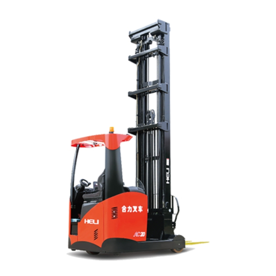
Sit-on type lithium battery powered reach truck
Hide thumbs
Also See for G2 Series:
- Operation & service manual (96 pages) ,
- Operation & service manual (43 pages) ,
- Operation & service manual (77 pages)
Table of Contents
Advertisement
Quick Links
Advertisement
Table of Contents

Related Manuals for HELI G2 Series


Summary of Contents for HELI G2 Series
- Page 2 The G2 series 1.6-2.0t sit on type lithium battery powered reach trucks (CQD16-GB3SLi、CQD20-GB3SLi) are new offering of HELI to meet market needs based on G2 series 1.6-2.0t sit-on type battery powered reach truck and with a combination of advanced lithium battery management system. It has modern designed...
- Page 3 truck correctly and attain the highest function. It is necessary to read over the manual before operating the trucks. The rules and notices in the manual should be abided seriously by all of the relative people to enable these trucks in optimized working state for long period and bring the highest efficiency.
-
Page 4: Table Of Contents
CONTENTS I. Safety Instructions of Operation and Driving……………………………………..1 II. External View of Reach Truck……………………………………………………5 III. Main Specifications………………………………………………………………6 IV. Construction and Principle of Reach Truck………………………………………7 4.1 Transmission system………………………………………………………..7 4.2 Steering system………………………………………………………………9 4.3 Supporting wheel assembly and brake system…………………...…………11 4.4 Hydraulic system………………………………………………………...….25 4.5 Lifting system………………………………………………………….……35 4.6 Electric system………………………………………...……………………41 V. -
Page 5: Safety Instructions Of Operation And Driving
I. Safety Instructions of Operation and Driving 1. Drivers and equipment keepers should keep “safety first” in mind and operate according to the operation and service manual. 2. Transporting When transporting the forklift with containers or trucks: 2.1 Take the mast backward, turn off the battery and make the truck under parking state;... - Page 6 Figure 1 1. Safety switch pedal 2. Brake pedal 3. Acceleration pedal 4. Steering wheel 5. Key switch 6. Automatic centering 8. front lamp 9. LCD 10.180° and 360° shifting switch 11. Electromagnetic parking brake 12. Horn 13. Lifting and lowering operation switch 14.
- Page 7 wheel. 5.2 Pay attention to the state of mechanical, electrical, hydraulic system and MOSFET speed adjuster. 5.3 Turn on the key switch and pull up the emergency switch, set the direction to the desired position, depress the accelerator pedal gradually and keep suitable acceleration.
- Page 8 5.15 Do not adjust the pressure of the control valve and safety valve which has been adjusted well in our company as will. 5.16 Check the chain regularly. 5.17 According to the measurement method specified in JB/T3300, the maximize noise at the outboard of the truck should be no more than 80dB (A). 6.
-
Page 9: External View Of Reach Truck
II. External View of Reach Truck... -
Page 10: Main Specifications
Battery voltage/rated capacity Ah/v 48/404 48/404 (discharging electricity in 5 hours) Battery weight Drive motor power Lifting motor power 12.5 Steering motor power Transmission box HELI special transmission box Service brake Electromagnetic brake Working pressure of hydraulic 17.5 18.5 system... -
Page 11: Construction And Principle Of Reach Truck
IV. Construction and Principle of Reach Truck 4.1 Transmission system 4.1.1 Working principle The drive unit of the truck is compact and reasonable arranged. Please see table 1 for its main performance parameters and figure 4-1-1 for structure. The working principle is that the output shaft of the motor is connected with drive gear through woodruff key, positioned through cone fixed core and fixed through lock nut. - Page 12 Figure 4-1-1 Drive unit 1. Redactor upper housing 2. Reductor lower housing 3. Output shaft 4. Nut 5. Oil retainer ring 6. Bearing 32209 7. Washer 8. Retainer ring 9. Spacer bush 10. Plug 11. Spiral bevel gear 12. Washer 13.
-
Page 13: Steering System
successively; 3) Remove the retainer ring and oil seal successively on the lower end of the bearing seat; 4) Remove the outer retainer ring on the output shaft of the drive motor; 5) Remove bearing seat. 4.2 Steering system Electric power making rear wheel Steering system type steering Steering motor... - Page 14 steering. The steering column assembly is assembled at the frame of the truck, and its site can be adjusted according to different demand as will. Figure 4-2-1 1. Steering wheel 2. Steering cover 3. Tightness adjusting switch 4. Steering bracket 5.
-
Page 15: Supporting Wheel Assembly And Brake System
1. Steering motor 2. Planet wheel deceleration box 3. Small gear 4. Big gear Figure 4-2-2 Steering deceleration mechanism 4.3 Supporting wheel assembly and brake system 4.3.1 Supporting wheel assembly The truck is of three wheel type and the front supporting is two symmetric located supporting wheels(see figure 4-3-1(a)(b)). - Page 16 1. drive wheel 2. Chassis assembly 3. Supporting wheel assembly Figure 4-3-1 (b) three wheel supporting diagram for CQD20-GB3SLi Supporting wheel assembly for CQD16-GB3SLi ( see figure 4-3-2(a) is made up of wheel (item 1), external shaft of load wheel (item 2), inner shaft of load wheel (item 3), double row angle contact ball bearing (item 11), front wheel electromagnetic brake (item 12), screw, washer and nut and so on.
- Page 17 shaft on the supporting leg channel steel. Make the supporting shaft match with double row angle contact ball bearing inner ring. Install axle pad (item 6) and washer 40( item 4) successively into shaft end. Then tighten with nut M40X1.5(item 5) and lock with washer 40( item 4).
- Page 18 13. supporting wheel shaft 14. Supporting leg channel steel 15.mud guard Figure 4-3-3(a) CQD16-GB3SLi reach truck supporting wheel assembly installation drawing Supporting wheel assembly of CQD20-GB2S( see figure 4-3-2(b)) is made up of wheel (item 1), external shaft of load wheel (item 2), inner shaft of load wheel (item 3), double row angle contact ball bearing (item 11), front wheel electromagnetic brake (item 12), screw, washer and nut and so on.
- Page 19 wheel through screw M10X30 (Item 6). The tighten torque of the screw is 55Nm and apply anaerobic adhesive GY-340. ○ 4 Then install the external shaft (item 2) into the inner ring of two double row angle contact ball bearings in the rim inner hole. Install shaft gasket (item 10), washer 40(item 8) into the shaft end one by one, then tighten it with nut M40X1.5 (item 9) and lock it with washer 40 (item 8).
- Page 20 Figure 4-3-2(b) CQD20-GB3SLi supporting wheel assembly 1. wheel 2. External shaft of the load wheel 3. Inner shaft of the load wheel 4. Screw M5x8 5. Screw M8x20 6. Screw M10x30 7. Retainer ring 68 8. washer 40 9. Nut M40x1.5 10. Shaft gasket 11.
- Page 21 Figure 4-3-3(b) CQD20-GB3SLi supporting wheel assembly 1. supporting wheel 2. External shaft of the supporting wheel 3. Inner shaft of the supporting wheel 4. Screw M5X8 6. Screw M10X30 9. Nut M40X1.5 11. Double row angle contact ball bearing 12. front wheel electromagnetic brake 13.
- Page 22 4.3.2 Brake system Service brake Notes when assembling front wheel electromagnetic brake Install spring self adjusting mechanism into 6ф20 holes respectively on the supporting wheel rim. Connect the armature of the electromagnetic brake with the supporting wheel with screw M8X30 (item 13) through self adjusting mechanism. Make sure the clearance between the armature and the rim is 1.60mm.
- Page 23 Figure 4-3-5(a) front wheel electromagnetic brake installation diagram for CQD16-GB3SLi Figure 4-3-5(b) front wheel electromagnetic brake installation diagram for CQD20-GB3SLi...
- Page 24 Parking brake Electromagnetic parking brake which is on the top of the shaft end cover of the AC type traction motor is applied on the truck (see figure 4-3-5). The friction disc is together with motor shaft. When the key is OFF or the emergency switch is pressed, the truck has no power, then the electromagnetic parking brake‘s electromagnet has no power.
- Page 25 1. Electromagnetic parking brake 2. Socket head cap screw M8x16 3. Washer 8 4.Shin 8 Figure 4-3-7 Electromagnetic parking brake assembling diagram 1 5. key 8x25 6. Retainer ring 25 Figure 4-3-8 Electromagnetic parking brake assembling diagram 2 See figure 4-3-7 and figure 4-3-8 for electromagnetic parking brake assembling. ○...
- Page 26 Make sure the airgap between the basis of the electromagnet and the amature is 0.3mm. Thus electromagnetic brake can brake reliably when getting electricity and released reliably when power off. Please see figure 4-3-9 for electromagnetic brake assembling dimensions. Figure 4-3-9 Rated airgap diagram 4.3.3 polyurethane tyre Polyurethane, as a kind of high polymer elastomer material, is a new material between rubber and plastics.
- Page 27 3. Higher ambient humidity If the environmental humidity is over 80% for a long period of time (more than 3 days), it is suggested that the bearing capacity should be reduced to 80% of the standard given by us at a specific speed, or the speed should be reduced to 60% of the standard given by us at a specific capacity.
- Page 28 Φ343X114 Φ329 Z3800-343114 Drive wheel Φ343X135 Φ329 Z3830-343135 Drive wheel Φ330x135 Φ317 QB744-40201 Load wheel Φ330X100 Φ317 Q78B4-40311 Load wheel Φ330x100 Φ317 Q7B04-40201 Load wheel Φ285x100 Φ274 Q6H84-40201 Load wheel Φ285x100 Φ274 Q6H04-40201 Load wheel Φ250x95 Φ240 Q60D4-40201 Load wheel Φ175x99 Φ168 W81L4-40211...
-
Page 29: Hydraulic System
4.4 Hydraulic system Model DSG05 Type Gear pump 20ml/r Nominal displacement Rated pressure 20MPa Hydraulic pump Highest pressure 22.6MPa Oil temperature -20℃~100℃ Hydraulic oil(mineral oil),viscosity :9~430mm Applicable oil Suction pressure -0.02~0.1MPa Model 15.4002.009/00 full proportion control Control valve Front and rear reach with balance valve (comfort Function Tilting self lock valve... - Page 30 The hydraulic system is made up of hydraulic oil tank, hydraulic oil pump, control valve, front lifting cylinder, rear lifting cylinder, front reach cylinder, tilting cylinder, side shifting cylinder pipelines and so on. comfort type full proportion system and economic decline proportion system are optional for control valve. See figure 4-1 and 4-2 for principle diagram.
- Page 31 Reaching Side shifting Lifting Tilting Figure 4-4-2 Economic type decline proportion system hydraulic principle diagram 4.4.1 Hydraulic oil tank The hydraulic oil tank is used to store oil and besides it can dissipate heat in the oil (when the environment temperature is low, it can be used to keep the heat in the oil), dispel the gas in the oil and sediments dirt in the oil.
- Page 32 7. Oil adding cover assembly 8. Combined washer 9. Oil draining plug 10. Magnet φ68/φ37x4 The return oil filter is used to keep the cleanness of the hydraulic oil. Change the filter after three months or 600h for the first time. In the future, change it every six months or every 1200h.
- Page 33 4.4.3 Control valve Control valve which achieves working devices lifting, front reach, tilting, side shifting and hydraulic system protecting integrates pressure control, flow control and direction control. Comfort type full proportion control valve and economic type decline proportion valve are optional. Comfort type full proportion control valve applies full proportion system control to achieve multi function simultaneous operation.
- Page 34 and corresponding electricity condition. ○ 1 lifting: 1. Lifting control electromagnetic proportion valve gets electricity. ○ 2 lowering : 2. Lowering control electromagnetic proportion valve gets electricity. ○ 3 front reaching: 8. Electromagnetic proportion directional valve gets electricity ○ 4 backward reaching: 7. Electromagnetic proportion directional valve gets electricity.
- Page 35 Figure 4-4-6 Economic type decline proportion valve 1. Lifting control electromagnetic proportion valve 2. Lowering control electromagnetic proportion valve 3. Emergency manual lowering valve 4. System overflow valve 5-10. Electromagnetic directional valve 11. Balance valve 12-13. Overload oil adding valve Economic type decline proportion valve applies decline proportion control and motor control.
- Page 36 ○ 5 tilting forward: 6. Electromagnetic proportion directional valve gets electricity. ○ 6 Tilting backward: 5. Electromagnetic proportion directional valve gets electricity. ○ 7 left shifting: 9. Electromagnetic proportion directional valve gets electricity. ○ 8 Right shifting: 10. Electromagnetic proportion directional valve gets electricity.
- Page 37 1. Pipeline anti-bursting valve 2. Cylinder tube assembly 3. Plunger 4.Cushion collar 5. Plunger rod 6. Cylinder cover 7. Plug 8. O ring 9. Retainer ring 10. Bearing 11.O ring 12. Seal ring for shaft 13. Guide ring 14. Dust proof ring Figure 4-4-8 Rear lifting cylinder structure 1.
- Page 38 4.4.5 Front reach cylinder The front reach cylinder is of piston type double acting hydraulic cylinder to realize mast moving backward and forward. The front reach cylinder is made up of piston, piston rod, cylinder body, cylinder bottom, guide sleeve and sealing parts. End clearance buffering technology is applied to reduce the shock when the cylinder moving to the end.
-
Page 39: Lifting System
realize fork left and right shifting. See figure 4-12 for its structure. Figure 4-4-12 Side shifting cylinder structure 1. Cylinder tube assembly 2. Plunger rod assembly 3. Side shifting cylinder cover 4. O ring 5. U ring 6. Dust proof ring 7. - Page 40 Cross section of inner mast channel steel: Cross section of middle mast channel steel: Figure 4-5-1 Cross section of mast The inner mast, outer mast and middle mast are welded structure. The middle of the outer mast is installed onto the mast support through support axle and the bottom of the outer mast is connected to the mast support through connecting plate with bolt.
- Page 41 Roller: Combined roller: Φ89.15 Lifting: Rear cylinder chain: LH046 Front cylinder chain: LH646 Lifting system: hydraulic type Tilting device: hydraulic type Side shifting device: hydraulic type Fork space adjusting device: manual type 4.5.2 Side shifter The side shifter is made up of side shifting rear bracket, side shifting front bracket, tilting bracket, tilting cylinder and side shifting cylinder and so on.
- Page 42 Tilting cylinder is installed between side shifting rear bracket and tilting bracket. The stretch out and draw back of piston rod realizes side shifter tilting forward and backward. Side shifting rear bracket Side shifting front bracket Side shifting cylinder Tilting bracket Tilting cylinder Figure 4-5-2 Side shifter structure 4.5.3 Roller position and adjusting...
- Page 43 Figure 4-5-4 Combined roller structure 1. Main roller train 2. Bracket element 3. Retainer ring for shaft 4. Dust proof piece 5. Spindle nose 6. Adjusting screw 7. Anti-loose piece 8.Locating pin Note: (a) Adjust the side roller clearance to 0.5mm with adjusting screw. (b) Apply grease to the surface of the roller and connecting surface with the mast.
- Page 44 Middle mast beam Adjusting shim Rear lifting cylinder Figure 4-5-5 Rear lifting cylinder installation instruction (1) Install the plunger rod into the middle mast beam after adding adjusting shim into the plunger rod head. (2) Lift the mast slowly to the max. cylinder travel distance. Check if the two cylinders are synchronized.
-
Page 45: Electric System
Chain End connector Adjusting nut Lock nut Figure 4-5-6 Chain installation instruction 4.6 Electric System 4.6.1 General description The electric system is equipped with a whole AC control system. With the system, the control of the whole truck can be low noisy, high efficient, smooth and safe. - Page 46 1) CAN bus technology The AC type electric reach truck applies the CAN bus technology. It links with each CAN module (traction control module, lift control module, steering control module, instruments display module) and acts as a connection point between the outside equipments and the CAN bus.
- Page 47 (1) Instruction of LED indicator Parameters Description Note tortoise speed Fault indicator It turns on when one of the controllers has fault. Battery It turns on when the electric quantity is lower indicator than 20%. Lift lock It turns on when the electric quantity is lower indicator than 10%.
- Page 48 Parameters Description Standard Enhanced When the hourglass symbol is on, it indicates that it is timing, and • • ① the number shows the current truck working time. Hour meter When the truck starts to work, the working timer starts to count. The arrow represents the direction of the steering wheel;...
- Page 49 Fork moving It displays the direction that fork moves towards. Up, down, ○ • direction forward, backward, forward, backward. Automatic The system is under automatic picking condition and it will not • ○ picking appear with the icon of automatic place at the same time. Code target •...
- Page 50 Number Set the pre-set height mode in home page and skip to the set key 3 interface of fork height Number Automatic picking is activated under home page. key 4 Number The standard display and enhanced display are shifted key 5 under home page.
- Page 51 traction motor and pump motor. It has regenerative brake function, CAN bus port and digital control function (based on motor speed feedback). Allowable working environment temperature: -30℃~+40℃ , Max. allowable working temperature: 85℃. Protection function of the ACS traction motor controller: a) battery polarity protection b) incorrect connection protection c) over heat protection;...
- Page 52 function switch inching. And also the function can realized through turning on the electric lock. ● The working environment temperature should be in the range of -30℃-40℃. The highest work temperature that is permitted is 85℃. ● Protection function of the steering motor controller: a) Battery polarity protection;...
- Page 53 CQD16-GB3SLi motor specifications Item Optional Optional Standard Model 3.2V/200Ah 16V/202Ah 3.2V/107Ah Capacity 400Ah 404Ah 320 Ah Voltage Unit 15 strings 15 strings CQD20-GB3SLi motor specifications Item Optional Optional Standard Model 3.2V/252Ah 16V/202Ah 3.2V/200Ah Capacity 500Ah 404Ah 400 Ah Voltage Unit 15strings 15strings Note: Cut off the electricity before checking and maintaining the motors to avoid...
- Page 54 B) Battery usage The correct use and daily maintenance of lithium battery have a great impact on the performance and service life of lithium battery. Therefore, the user must carry out maintenance according to the provisions of the operation and maintenance manual provided by the manufacturer and the actual situation.
- Page 55 battery must not be close to the open fire; (5) The battery surface shall be dry and clean. 6) Panel switch Switches on the panel can be on or off according to the customer’s choose. : When the two buttons are pressed, the steering wheels return to center position automatically.
- Page 56 censor, driving of the connector, can-bus connector (3) Check when working: the circuit of the watch dog, the driving of the connector, the current sensor, can-bus connector (4) Continuously check: inverter temperature, motor temperature The fault code will be sent by CAN-BUS and the code and module node will display in the meter.
- Page 57 complete. Please disconnect the side shifting switch The attachment switch is closed ERROR attachment switch is before the steering calibration is activated when starting complete. Please disconnect the attachment switch The lifting switch is closed before ERROR lift switch is activated the steering calibration is complete.
- Page 58 1. Traction motor temperature is too WARNING high temperature of high. traction motor 2. Traction motor thermistor fault 1. Traction motor thermistor fault 2. ERROR fault of traction motor Harness fault, traction motor temperature sensor temperature sensor connection wire broken 1.
- Page 59 ERROR interior power supply Check the connecting wire of motor fault of traction driver encoder and temperature sensor WARNING Low temperature of Low temperature of controller pump driver WARNING high temperature of High temperature of controller pump driver ERROR Pump driver temperature Controller temperature sensor error sensor error 1.
- Page 60 1. Replace the precharge resistor. ERROR Pump driver precharge 2. The battery voltage is low. timeout 3. The harness is broken and iron is made ERROR low voltage of pump Low battery electric quantity driver ERROR high voltage of pump high voltage of battery driver 1.
- Page 61 drive coil 1、Check if there short circuit or ERROR fault of steering open circuit of output harness; driver’s output port. 2、open circuit or short circuit of drive coil 1. low temperature of Steering WARNING low temperature of motor steering motor 2.
- Page 62 make sure there is clear sound. Check the thumb switch every three months. Check the cables of the battery, chopper and motor. Make sure they are insulate and well connected. Check the main cables every three months. Check the pedal and the mechanical working of the thumb switch. Check the returning springs.
- Page 63 Figure 4-6-1 1. sliding block(left) 2. sliding block(right) Figure 4-6-2 1.lock pedal (2) Draw back the battery Push the forward/backward thumb switch forward and make the mast reach forward. Make the left sliding block and right sliding block to be straight. Put the battery on the mast seat and make left and right sides of the battery have the same clearance with the truck frame.
- Page 64 “click” sound. (At this time, keep your feet away from te lock pedal to avoid feet harm). Keep for 1s until the battery is locked firmly. Then push the forward/backward thumb switch forward and make the mast reach forward. Make the left and right sliding blocks horizontal.
- Page 65 Appendix : electric system principle diagram 选项 电机风扇 电控风扇 代号 名称 英文名称 代号 名称 英文名称 代号 名称 英文名称 代号 名称 英文名称 蓄电池 仪表 起升/下降拇指开关 接近开关0度 主接触器 行走电机 前移/后移拇指开关 接近开关90度 高度编码器 倒车继电器 起升电机 前倾/后倾拇指开关 K3、K4 风扇继电器 转向电机 左移/右移拇指开关 喇叭 行走控制器熔断器 步进电机 起升电磁阀...
-
Page 66: Troubleshooting
V. Troubleshooting 5.1 Transmission system problem Possible cause Remedies too much clearance between Adjust the gears Loud noise of gears when driving much wear of the gears Replace lower oil level in oil tank Add oil too much clearance between Loud striking noise when Adjust the gears... -
Page 67: Parking Brake System
work. Break off of electricity supply Reconnect power supply over large of brake gas gap Readjust brake gas gap replace the brake and readjust Damage of friction disc brake gas gap Damage of brake coil replace the brake Over small of brake gas gap readjust brake gas gap Voltage switch is on power off Check the electricity supply... - Page 68 Low pressure of system safety Adjust safety valve pressure valve Damage of lifting solenoid Replace lifting solenoid valve valve core Internal leakage of lifting Replace sealing ring cylinder Disconnect lifting Check and repair electromagnetic wiring Disconnect of control knob Check and repair wiring Front and backward moving Replace...
-
Page 69: Electric System
5.6 Electric system Problem Possible cause Remedies poor contact of the key switch Check and repair broken wire Connect again No signal after the turning on poor contact of the connector Check and repair of the key switch poor connection of the battery Tighten the bolt connector broken wire... -
Page 70: Maintenance
VI. Maintenance 6.1 Routine maintenance In the use of the work, especially during the first operation period of the new truck, carefully operation and timely adjustment, maintenance and service are all necessary for keeping the truck in good condition. Do as the following. (1) When a new truck has been used for 100 hours, replace the gear oil in transmission box, and tighten all fixing parts. - Page 71 3000h Replace it at High pressure Replace once when pipe damaged 6.2 Oil for forklift truck Trademark/code Trademark/code Name name(home) name(abroad) Hydraulic oil N32# or N46# ISOVG30 Gear oil 85W/90 SAE90/SAE80W 4604 compound brake Brake liquid JISK-2233 liquid 3# lithium base grease Lubricating grease JISK-2220, 1#,2# dropping point 170...
- Page 72 6.3 Lubricating chart...
-
Page 73: Others
VII. Others 7.1 The size and weight of the main takedown parts of the truck Type Unit CQD16-20-GB2S Parameter Max. overall 733× 1270× 1317 Overhead guard dimension Weight Max. overall 1150× 122× 40 dimension Fork Weight Mast Max. overall 2314× 448× 842 dimension (lift height 4600mm) - Page 74 Max. overall Mast 3564× 448× 842 dimension (lift height 8500mm) Weight 1488 Max. overall Mast 3730× 448× 842 (lift height dimension 9000mm) Weight 1535 Max. overall Mast 3898× 448× 842 (lift height dimension 9500mm) Weight 1584 Mast Max. overall 4064× 448× 842 (lift height dimension 10000mm)
- Page 75 7.3 Overhead guard disassembly Dismantle the truck’s right cover (remember to unplug the wire),and loose the bolt (M12× 45) connecting the overhead guard and truck body. Hook the overhead guard with a cord and you can take off the overhead guard. 7.4 Vibration specification Item Type...
Need help?
Do you have a question about the G2 Series and is the answer not in the manual?
Questions and answers