HELI G2 Series Operation & Service Manual
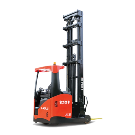
Ac electric reach truck standard type
Hide thumbs
Also See for G2 Series:
- Operation & service manual (96 pages) ,
- Operation & service manual (82 pages) ,
- Operation & service manual (77 pages)
Table of Contents
Advertisement
Advertisement
Table of Contents

Related Manuals for HELI G2 Series


Summary of Contents for HELI G2 Series
- Page 2 The G2 series2.0t sit on type battery powered reach trucks (CQD20-GC2S) are new offering of HELI to meet market needs. The new series is designed on the base of the advantages of some reach trucks made by domestic and foreign manufacturers and designed together with Italy Design Company.
-
Page 3: Table Of Contents
CONTENTS I. Safety Instructions of Operation and Driving……………………………………..1 II. External View of Reach Truck……………………………………………………5 III. Main Specifications………………………………………………………………6 IV. Construction and Principle of Reach Truck………………………………………7 4.1 Transmission system………………………………………………………..7 4.2 Steering system………………………………………………………………9 4.3 Supporting wheel assembly and brake system…………………...…………11 4.4 Hydraulic system………………………………………………………...….26 4.5 Lifting system………………………………………………………….……36 4.6 Electric system………………………………………...……………………42 V. -
Page 4: Safety Instructions Of Operation And Driving
I. Safety Instructions of Operation and Driving 1. Drivers and equipment keepers should keep “safety first” in mind and operate according to the operation and service manual. 2. Transporting Pay attention to the following instructions before transporting the forklift with containers or trucks: 2.1 Take the mast backward, turn off the battery and pull the parking brake;... - Page 5 Generally, after out of round in summer, the whole truck can be recovered after 10-15 minutes of operation; in winter, the whole truck can be recovered after 20-30 minutes of operation 4. Preparations for start 4.1 Read the manual carefully to get familiar with the meters, operating levers, construction and functions of the forklift before driving.
- Page 6 capacity; 4.6 Check all of the connectors and plugs in the electric system for reliable contact and accelerator pedal for effectiveness and flexibility; 4.7 Check hydraulic oil, electrolyte and brake fluid for leakage; 4.8 Check main fixing parts for tightness; 4.9 Make the trial of the mast for lifting, lowering, forward and backward tilting and the truck for steering and braking.
- Page 7 5.10 When releasing the thumb switch suddenly during mast lowering, the mast will stop after a short time. 5.11 When travelling with load, tilt the mast backward, retract the mast and keep the load as low as possible. Do not travel or steer when lifting the mast. 5.12 When driving, be careful of the passersby, obstacles and rough road, and make sure there is enough clearance between the mast and the entrance.
-
Page 8: External View Of Reach Truck
II. External View of Reach Truck... -
Page 9: Main Specifications
Front reaching speed 0.11/0.11 Rated capacity Q(kg) 2000 Load center C(mm) Motor Max. gradeability, 10/15 loaded/unloaded Battery voltage/rated capacity Ah/v 500/48 (discharging electricity in 5 hours) Battery weight Drive motor power Lifting motor power Transmission box HELI special transmission box... -
Page 10: Construction And Principle Of Reach Truck
IV. Construction and Principle of Reach Truck 4.1 Transmission system 4.1.1 Working principle The drive unit of the CQD20-GC2S is compact and reasonable arranged. Please see table 1 for its main performance parameters and figure 4-1-1 for structure. The working principle is that the output shaft of the motor is connected with drive gear through woodruff key, positioned through cone fixed core and fixed through lock nut. - Page 11 Figure 4-1-1 Drive unit 1. Redactor upper housing 2. Reductor lower housing 3. Output shaft 4. Nut 5. Oil retainer ring 6. Bearing 32209 7. Washer 8. Retainer ring 9. Spacer bush 10. Plug 11. Spiral bevel gear 12. Washer 13.
-
Page 12: Steering System
successively; 3) Remove the retainer ring and oil seal successively on the lower end of the bearing seat; 4) Remove the outer retainer ring on the output shaft of the drive motor; 5) Remove bearing seat. 4.2 Steering system Electric power making rear wheel Steering system type steering Steering motor... - Page 13 steering. The steering column assembly is assembled at the frame of the truck, and its site can be adjusted according to different demand as will. Figure 4-2-1 1. Steering wheel 2. Steering cover 3. Tightness adjusting switch 4. Steering bracket 5.
-
Page 14: Supporting Wheel Assembly And Brake System
1. Steering motor 2. Planet wheel deceleration box 3. Small gear 4. Big gear Figure 4-2-2 Steering deceleration mechanism 4.3 Supporting wheel assembly and brake system 4.3.1 Supporting wheel assembly CQD20-GC2S truck is of three wheel type and the front supporting is two symmetric located supporting wheels(see figure 4-3-1). - Page 15 supporting shaft (item 2), retainer ring (item 3), double row angle contact ball bearing (item 11), lock bolt (item 5) and bushing (item 6). Apply proper lubricating grease between two double row angle contact ball bearings and change regularly (every two month).
- Page 16 Figure 4-3-3 Supporting wheel assembly 1. Supporting wheel 2. Supporting shaft 3. Retainer ting 68 4. Double row angle contact ball bearing 5. Lock bolt 6 bushing 7. Screw M1225 8. Brake assembling plate 9. Fixing plate 10. Hydraulic brake 11.
- Page 17 limit with retainer ring 68 (item 3). ○ 3 Fix hydraulic brake (item 10) to the place where is between brake mount plate (item 8) and fixing plate (item 9) with four screw M1225. ○ 4 Match the preliminary wheel assembly with brake assembly. Make sure the clearance between brake and rim inner friction surface is between 0.2mm and 1.5mm.
- Page 18 Service brake Front two wheel braking type, internal expansion, Rear wheel driving Type hydraulic type, pressure motor AC electric brake limit valve Pedal ratio 5.75 Master cylinder bore 19.05mm Operating cylinder bore 22.22 AC motor electric brake Inner diameter of brake drum 220mm Outer diameter of brake drum Front wheel:330mm...
- Page 19 1. Right oil pipe assembly 2. Left oil pipe assembly 3. Screw M12X25 4.Right brake assembly 5. Left brake assembly 6. Two-way 7. Oil pipe assembly 8. Three-way 9. Accelerating and brake pedal assembly 10. Bolt 11. Combined washer 10 12. Combined washer 12 13.
- Page 20 1.Pushing rod assembly 2. Protection cover 3. Elastic retainer ring 4. Piston assembly 5. Oil cup assembly 6. Oil cup connection bolt 7. Washer 8. O ring 15.2X2.4 9. Cylinder body 10. Dust proof plug Figure 4-3-6 master cylinder (2) Brake The brake includes two kinds: wheel (supporting wheel) brake and drive motor brake(on top of drive wheel).
- Page 21 Figure 4-3-7 wheel hydraulic shoe type brake (3) Brake force limiter Brake force limiter consists of cylinder body, piston, spring, cup, bushing, retainer ring and seal. Its primary function is transferring the oil in the master cylinder after reducing the oil pressure to the operating cylinder. And then front wheel brakes. Its max.
- Page 22 Figure 4-3-8 Brake force limiter (4) Brake pedal The brake pedal is installed on brake supporting plate on the middle plate through bracket. See figure 4-3-9. When pedal is moving, the piston is moved through pushing rod and thus oil circuit pressure is increased. (5) Brake pedal adjusting (see figure 4-3-9) ●...
- Page 23 1.Assembly plate 2. Brake pedal assembly 3. Mater cylinder 4. Brake force limiter 5. Oil pipe assembly 6. Bolt M8X25 7. Retainer ring 25 8. adjusting shim 9. Pin 2.5x26 10. Pin B10X28 11. Screw M8X16 12. washer 8 13. Nut M8 14.
- Page 24 the brake tank’s middle level or be a little higher than min. level. Thus brake is ensured to be reliable and safe. Parking brake Electromagnetic parking brake which is on the top of the shaft end cover of the AC type traction motor is applied on the truck (see figure 4-3-10). The friction disc is together with motor shaft.
- Page 25 assembling diagram. It is mainly made up of electromagnetic parking brake (item 1), key 8x25(item 5), retainer ring 25 (item 6), screw and washer and so on. 1. Electromagnetic parking brake 2. Socket head cap screw M8x16 3. Washer 8 4.Shin 8 Figure 4-3-11 Electromagnetic parking brake assembling diagram 1 5.
- Page 26 of the traction motor with 3 socket head cap screws M8x16 (item 2). The tighten torque of the screw is 25Nm and apply anaerobic adhesive GY-340. (9) Fix the friction disc built-in spine sleeve of the electromagnetic parking brake with travelling and traction motor shaft through key 8x25 (item 1).
- Page 27 The optimum operating temperature of PU wheels is - 5 - 30 C. If the ambient temperature exceeds this range, attention should be paid to the capacity or running speed of PU wheels in use, and adjustments should be made according to our suggestions.
- Page 28 During the daily use of the truck, the tyres will wear normally, and improper use will cause premature tire early damage. Avoid driving on rough and bumpy roads, overload, overspeed and long-term (≥ 20h) continuous operation. When the ratio of wear value to tyre diameter is greater than 4%, it is recommended to replace the tyre;...
-
Page 29: Hydraulic System
4.4 Hydraulic system Model DSG05C20 Type Gear pump 20ml/r Nominal displacement Rated pressure 20.6MPa Hydraulic pump Highest pressure 22.6MPa Oil temperature -20℃~100℃ Hydraulic oil(mineral oil),viscosity :9~430mm Applicable oil Suction pressure -0.02~0.1MPa Model MSV04-43391-51 Manual control Control valve Function Front and rear reach with balance valve System pressure 20MPa Type... - Page 30 Figure 4-4-1 hydraulic system principle diagram 4.4.1 Hydraulic oil tank The hydraulic oil tank is used to store oil and besides it can dissipate heat in the oil (when the environment temperature is low, it can be used to keep the heat in the oil), dispel the gas in the oil and sediments dirt in the oil.
- Page 31 Figure 4-4-2 hydraulic oil tank 1. Hydraulic oil tank 2. Oil suction port 3. Oil return port 4. Oil adding cap 5. Oil level gauge 6. Return oil filter 7. Oil draining port 8. Magnet The return oil filter is used to keep the cleanness of the hydraulic oil. Change the filter after three months or 600h for the first time.
- Page 32 pipe to fill the gears. With the rotation of chamber, gears bring the oil into the left chamber from right chamber to make the pressure of the left chamber increase and the oil goes out from the oil discharging port. Because the gears keep going, the oil suction port and oil discharging port keep sucking oil and discharging oil.
- Page 33 Figure 4-4-4 Control valve 1. lifting and lowering valve 2. Overload oil adding valve 3. Reaching forward valve 4. Tilting valve 5. Side shifting valve 6. oil pump port 7. Safety valve 8. Lifting speed adjusting sensor 9. oil tank port 4.4.4 Control valve operation The control valve is operated with the valve levers.
- Page 34 Figure 4-4-5 control valve operation 1. lifting and lowering operating knob 2. Reaching forward operating knob 3. tilting operating knob 4. Side shifting operating knob 5. bushing 6. Connecting shaft 7. Valve rod bracket 8. Connecting rod 9. pin 10. Pin bolt 11.
- Page 35 the mast fall down when you pull the lever forward. The mast tilt forward when you push the lever forward, and the mast tilt backward when the lever backward. When you push the reach lever forward, the mast goes forward and also reaches lever backward the mast backward.
- Page 36 Figure 4-4-8 Rear lifting cylinder structure 1. Cylinder bottom assembly 2. Pipeline anti-bursting valve 3. shutter 4. O ring 5. Cushion collar 6. Steel cable retainer ring 7. plug 8. Cylinder tube 9. Plunger rod 10. Bearing 11. Guide sleeve 12.
- Page 37 piston, piston rod, cylinder body, cylinder bottom, guide sleeve and sealing parts. End clearance buffering technology is applied to reduce the shock when the cylinder moving to the end. See figure 4-4-10 for its structure. Figure 4-4-10 Front reach cylinder structure 1.
- Page 38 Figure 4-4-12 Side shifting cylinder structure 1. Cylinder tube assembly 2. Plunger rod assembly 3. Side shifting cylinder cover 4. O ring 5. U ring 6. Dust proof ring 7. Retainer ring 8. Adjusting shim 4.4.9 Hydraulic system troubleshooting Problem Possible cause Remedies oil leakage in the pipeline or...
-
Page 39: Lifting System
4.5 Lifting system The lifting system is a telescopic triple full free lift mast. It consists of inner mast, middle mast, outer mast and integral side shifter. 4.5.1 inner mast, middle mast and outer mast The lifting system is a telescopic triple full free lift mast. It consists of inner mast, middle mast, outer mast and integral side shifter. - Page 40 Figure 4-5-1 Cross section of mast The inner mast, outer mast and middle mast are welded structure. The middle of the outer mast is installed onto the mast support through support axle and the bottom of the outer mast is connected to the mast support through connecting plate with bolt. The outer mast channel steel is of C type and combined roller is installed on its upper end.
- Page 41 Fork space adjusting device: manual type 4.5.2 Side shifter The side shifter is made up of side shifting rear bracket, side shifting front bracket, tilting bracket, tilting cylinder and side shifting cylinder and so on. see figure 4-5-2. There are three pairs of combined roller to ensure the stable moving of side shifter in the inner mast channel steel and bear vertical and lateral load.
- Page 42 Side shifting rear bracket Side shifting front bracket Side shifting cylinder Tilting bracket Tilting cylinder Figure 4-5-2 Side shifter structure 4.5.3 Roller position and adjusting There are two kinds of roller. One is combined rollerⅠwith inclined 1°and combined rollerⅡwith straight flange. Only the lower end of the middle mast uses combined rollerⅡwith straight flange and the other positions use combined rollerⅠwith inclined 1°...
- Page 43 Figure 4-5-4 Combined roller structure 1. Main roller train 2. Bracket element 3. Retainer ring for shaft 4. Dust proof piece 5. Spindle nose 6. Adjusting screw 7. Anti-loose piece 8.Locating pin Note: (a) Adjust the side roller clearance to 0.5mm with adjusting screw. (b) Apply grease to the surface of the roller and connecting surface with the mast.
- Page 44 Middle mast beam Adjusting shim Rear lifting cylinder Figure 4-5-5 Rear lifting cylinder installation instruction (1) Install the plunger rod into the middle mast beam after adding adjusting shim into the plunger rod head. (2) Lift the mast slowly to the max. cylinder travel distance. Check if the two cylinders are synchronized.
-
Page 45: Electric System
Chain End connector Adjusting nut Lock nut Figure 4-5-6 Chain installation instruction 4.6 Electric System 4.6.1 General description The electric system is equipped with a whole AC control system. With the system, the control of the whole truck can be low noisy, high efficient, smooth and safe. - Page 46 1) CAN bus technology The AC type electric reach truck applies the CAN bus technology. It links with each CAN module (traction control module, lift control module, steering control module, instruments display module) and acts as a connection point between the outside equipments and the CAN bus.
- Page 47 (1) Enter into intelligent display menu through 6 operating button (if applicable): Key 5----the same function with the OUT key on hand console. Key 4---the same function with the SET DOWN key on hand console. Key 3: the same function with the SET UP key on hand console. Key 2: the same function with ROLL DOWN key on hand console.
- Page 48 (2) The steering angle figure will be shown after self checking.(traction hour will be replaced.) Steering angle indicator (3) Safety switch and brake display: the truck is braked when safety pedal is released. At that time the truck can not travel but it can steer, lift, moving forward and backward, tilt and the symbol on the meter is on all the time.
- Page 49 Battery electricity quantity indicator (5) Timer: when the truck gets electricity, timer begins to work. Customer can maintain the truck in regulated time according to the working hours shown on the truck accumulated by the timer. (6) Fault code display: if fault occurs, figure is on all the time.
- Page 50 Figure 4-6-6 Control assembly Figure 4-6-7 Steering controller A) Traction and pump motor controller Tractor motor controller type: ZAPI ACE2 48V/350A ACE2 controller which is three phase AC asynchronism motor inverter controls traction motor and pump motor. It has regenerative brake function, CAN bus port and digital control function (based on motor speed feedback).
- Page 51 g) Mis-starting protection The following functions can be realized through controller’s hand console: a) On line inspection and adjusting on traction and lifting control system b) On line correction on travelling accelerator and lifting speed adjusting signal c) Fault detection and inquiry on traction and lifting control system B) Steering motor controller Italy imported EPS-ACO controller is installed on the truck which applies advanced electric powered steering control system.
- Page 52 a) On line check and adjusting of the steering control system; b) On line fault check and query about the steering control system. It is convenient to maintain the system. Note: ◆ Test the truck with four wheels raised after the controller being fixed, in that case there will be no danger even the connection is in error.
- Page 53 The battery is made up of + pole plate, - pole plate, separator, battery cover and electrolytic. Type 5PzS500 Capacity 500Ah/5h Voltage Electrolytic density 1.280-1.290g/cm (25℃) Monadelphous number Fig. 4-6-7 battery construction Note: Imported battery is optional. B) The usage of battery The usage and routine maintenance of the battery will influent battery life and performance.
- Page 54 ○ 8 Charge the battery in time (in 24 hours after use). The performance of the battery will drop caused by the vulcanizing of the pole plate if the battery is not charged in time, over charged, over used and not recharged after a long time of no using.
- Page 55 The cause that made the battery error is various, except the effect of the quality manufacture and transport storage, mostly due to the improper maintenance. Find out the faults and analyze the causation as soon as possible to exclude. The characteristics of faults, causation and repair measure are bellowed; fault Characteristics Causation...
- Page 56 1) Being unsuitable to the electrolytic quality standard Frequent discharging Clean Shedding 1) Decrease of the battery charging or over precipitate when off of the capacity charging the actuality is not reactive 2) Turbid electrolytic discharging severity. matter 3) Much precipitate 3)High .electrolytic 2) Discard when temperature when...
- Page 57 ●The auto liquid replenishment device shall ensure the correct liquid pressure. ● Liquid storage devices and pipelines shall be kept clean and there shall be no dirt. ●Only special liquid for batteries shall be used. ●It is strictly forbidden to flush the injection plug with tap water. ●...
- Page 58 censor, driving of the connector, can-bus connector (3) Check when working: the circuit of the watch dog, the driving of the connector, the current sensor, can-bus connector (4) Continuously check: inverter temperature, motor temperature Ways of diagnosis: the digital hand manual which can supply detailed diagnosis information;...
- Page 59 1. incorrect wiring or fault of motor circuit; check if the three phase connecting of the motor is correct; check if the motor to earth leaks; check if the motor coil has broken circuit. 2. Check if the main contactor is firmly connects and the connecting points are worn.
- Page 60 module has fault. Change the controller. The controller temperature is higher than 85℃ TEMPERAURE High temperature when total power is allowed. ( the temperature is related to parameter “MAXIMUM CURRENT”). Corresponding relations: Parameter setting alarm temperature MAXIMUM CURRENT=50% 96℃ MAXIMUM CURRENT=60% 94℃...
- Page 61 normally. If the main contactor’s coil has no fault, DRIVER contactor driver change the controller. VACC NOT OK Accelerator The test is made in standby. This alarm indicates that fault the accelerator voltage is 1V greater than the minimum value programmed by the PROGRAM VACC function. Possible causes: 1.
- Page 62 minimum value is higher than the backward maximum value or the backward minimum value is higher than the foreword maximum value, the fault occurs. Check if the potentiometer is ok or recollect the data. WAITING Wait for node One controller receives a signal that the other signal can NODE signal no t work normally and the controller is under waiting...
- Page 63 The max. current gain parameter is factory setting fault value. It means the max, current adjusting parameter program is not yet operated. Remedy: HELI technician set the correct program on current gain parameter. ANALOG INPUT Analog signal When A/D input by all analog signal is converted into a input fault fixed value, the fault occurs.
- Page 64 controller. WRONG Zero voltage VAM high terminal voltage feedback voltage is very ZERO VOLTAGE fault higher or lower than 2.5V, that means the controller circuit is broken. Check the following items: Motor inner side connection Motor power cable connection Drain current between motor and truck external case If motor is well connected, the interior of the controller has fault, change the controller.
- Page 65 Remedy: turn off the key switch and turn it on again. if fault still occurs, change the controller. DRIVER Auxiliary Auxiliary coil drive circuit can not drive the load. the OPEN output drive device itself or drive coil is damaged. Change the fault controller.
- Page 66 EEPROM KO Damage Fault in the area of memory in which the adjustment programmable parameters are stored; this alarm inhibits machine memorizer operation. If the defect persists when the key is switched OFF and ON again, replace the logic. If the alarm disappears, remember that the parameters stored previously have been cancelled and replace by the default values.
- Page 67 check if the motor to earth leaks; check if the motor coil has broken circuit. 2. Change controller STBY I HIGH HIGH The output signal of the current sensor tested by STANDBY micro-control system exceeds the allowable range of CURRENT the non-running current.
- Page 68 the motor. If the fault still occurs when the motor is cold, check the wirings. If all are ok, change the controller. DRIVER Driver short When the key is turned off, the microprocessor SHORTED circuit will check if the driver of the main contactor has short circuit.
- Page 69 edition and programming. WATCHDOG #1 Watchdog The watchdog is activated before the software is started fault 1 when starting. The watchdog signal is out of effect in spare use or travelling condition. Watch dog hardware electric circuit or microcontroller output part are damage. Change the controller. WATCHDOG #2 Watchdog The watchdog is activated before the software is started...
- Page 70 ZERO VOLTAGE fault higher or lower than 2.5V, that means the controller circuit is broken. Check the following items: Motor inner side connection Motor power cable connection Drain current between motor and truck external case If motor is well connected, the interior of the controller has fault, change the controller.
- Page 71 ACQUISITION acquisition need to be done. The fault will disappear after adjusting. CAN communicating fault between pump and traction. MESSAGE message Check the CAN wiring software setting and edition information. CHECK UP NEED Maintenance It is time to maintenance and check the truck. time THERMIC Temperature...
- Page 72 12s. LOGIC FAILURE This alarm occurs in the rest Change the controller state if the output of the voltage amplifilter of the phase Vw-Vv have a drift larger than ±0.25V. LOGIC FAILURE This alarm occurs in the rest Change the controller state if the output of the voltage amplifilter of the phase Vu-Vw have a drift larger than ±...
- Page 73 TEMPERATURE temperature of the controller controller. base plate overtakes 75℃. MOTOR When DIAG MOTOR TEMP is 1. Check if the temperature sensor is TEMPERATURE temperature is higher than 2. if it is ok, improve the cooling 150 ° measured device. temperature sensor in motor, it will alarms.
- Page 74 with slave uC encoder. STEPPER MOTOR If the leading wire of D and Q Change the controller MISM are connected incorrectly, it will alarm. Normally, the voltage range increases and its frequency will increase. MOTOR LOCKED It will alarm when the max. The motor is locked: current of the steering motor’s 1.
- Page 75 NO SYNC Every 16ms, inside the code Change the controller cycle, the main uC rises and then lowers an input for the slave uC. When the slave uC detects no edge for more than 100ms on this input , this alarm occurs, this is just a watch dog function .
- Page 76 delay, the steer is not activated switch sensing iron block yet, the safety relays are open position. and the traction is stopped. WAITING FOR At key-on the EPS-AC0 nneds TRAC an assent from the traction controller to close the safety contacts and to turn onto operational mode.
- Page 77 Furthermore, this alarm occurs also if the main uC is detecting no limitation meanwhile the slave uC is detecting a steering limitation. CAN BUS KO This alarm occurs only when Check the CAN bus communication setting system and analyze the frames from PRESENT.
- Page 78 expected being closed. KM CLOSED This alarm occurs if the slave Change the controller uC detects the safety contact, of the main uC, closed when expected being open. KS CLOSED This alarm occurs if the main Change the controller uC detects the safety contact, of the slave uC, closed when expected being open.
- Page 79 VMN HIGH ENCODER ERROR VMN NOT OK BAD ENCODER SIGN NO FULL COND. STEER SENSOR KO RGT NO FULL COND STEER HAZARD LFT NO FULL COND PEDAL WIRE KO PU NO FULL COND PEDAL FAILURE CONTACTOR CLOSED TRACTION BRUSHES CONTACTOR OPEN PUMP BRUSHES BRAKE CON CLOSED DRIVER 1 KO...
- Page 80 “SERVICE REQUIRED” It is due to maintain the truck. “COIL SHORTD” This alarm occurs when there is a short circuit of the coil connected to output, so over current is produced on relative driver. Troubleshooting: ----check if the connected load is burnt or short circuit; ----check the relative wirings ----if the fault occurs when the load wirings are disconnected, it means the big current protection circuit of the intelligent display is damaged, change the display.
- Page 81 electric brush, circuit and the electric brush wear sensor; --- If the input point is ineffective check the input circuit of the intelligent instrument. 4.6.4 Routine maintenance Check the wear and connect condition of the contactor point. Check it every three months.
- Page 82 Push the forward/backward knob forward and make the mast reach forward. Make the left sliding block and right sliding block to be straight (refer to figure 4-6-9). Operator returns to driver’s seat, pull the forward/backward knob and make the mast go backward.
- Page 83 Make the left sliding block and right sliding block to be straight. Put the battery on the mast seat and make left and right sides of the battery have the same clearance with the truck frame. Pull the forward/backward thumb switch backward. The battery is drawn back with the mast moving back.
- Page 84 Appendix : electric system principle diagram...
-
Page 85: Troubleshooting
V. Troubleshooting 5.1 Transmission system problem Possible cause Remedies too much clearance between Adjust the gears Loud noise of gears when driving much wear of the gears Replace lower oil level in oil tank Add oil too much clearance between Loud striking noise when Adjust the gears... -
Page 86: Parking Brake System
work. Break off of electricity supply Reconnect power supply over large of brake gas gap Readjust brake gas gap replace the brake and readjust Damage of friction disc brake gas gap Damage of brake coil replace the brake Over small of brake gas gap readjust brake gas gap Voltage switch is on power off Check the electricity supply... -
Page 87: Electric System
4) much wear of the gears Change Check the o-ring or 5) oil leakage of the gears replace 1) too much wear of the Change gears 2) low pressure of the Adjust the pressure of the system safety valve 3) too much wear between the control valve and the Change levers lever... - Page 88 switch broken horn Change Long-working of the horn long-contact of the horn switch Check and repair broken fuse Change Abnormal working of the poor contact of the connector Cheek and repair illuminative lights broken bulb Change...
-
Page 89: Maintenance
VI. Maintenance 6.1 Routine maintenance In the use of the work, especially during the first operation period of the new truck, carefully operation and timely adjustment, maintenance and service are all necessary for keeping the truck in good condition. Do as the following. (1) When a new truck has been used for 100 hours, replace the gear oil in transmission box, and tighten all fixing parts. - Page 90 6.2 Oil for forklift truck Trademark/code Trademark/code Name name(home) name(abroad) Hydraulic oil N32# or N46# ISOVG30 Gear oil 85W/90 SAE90/SAE80W 4604 compound brake Brake liquid JISK-2233 liquid 3# lithium base grease Lubricating grease JISK-2220, 1#,2# dropping point 170...
- Page 91 6.3 Lubricating chart...
-
Page 92: Others
VII. Others 7.1 The size and weight of the main takedown parts of the truck Type Unit CQD20-GC2S Parameter Max. overall 733× 1270× 1317 Overhead guard dimension Weight Max. overall 1150× 122× 40 dimension Fork Weight Mast Max. overall 2314× 448× 842 dimension (lift height 4600mm) - Page 93 Max. overall Mast 3564× 448× 842 dimension (lift height 8500mm) Weight 1488 7.2 Mast disassembly Reach forward and tilt backward the mast, hook in the swing position of the mast with a cord; dismantle three high pressure hose in the bottom of the mast and loose the bolts (M18 connecting the mast seat and the lower end of the outer ×...
Need help?
Do you have a question about the G2 Series and is the answer not in the manual?
Questions and answers