
Related Manuals for Otto Bock Juvo


Summary of Contents for Otto Bock Juvo
- Page 1 Juvo Instructions for use (user) ..................
- Page 2 Juvo...
-
Page 3: Table Of Contents
Buttons and display functions ....................... 6.6.2.3 Adjustment possibilities ........................6.6.2.4 Environmental control via Bluetooth ....................... 6.6.2.4.1 Activating devices ..........................6.6.2.4.2 Pairing ............................... 6.6.2.4.3 Selecting the connected devices ......................6.6.2.4.4 Deactivating devices ..........................6.6.2.4.5 Operating mouse functions on a PC ...................... Juvo... - Page 4 R-Net control unit ..........................6.11.7 Joystick functions ..........................6.12 Manual seat functions .......................... 6.12.1 Safety instructions ..........................6.12.2 Manually elevating legrests ........................6.13 Lap belt ............................. 6.13.1 Adaptation ............................6.13.2 ..............................6.14 Control unit accessories ........................6.14.1 Separate LCD monitor ......................... Juvo...
- Page 5 Mechanical track stabiliser ........................6.16.7 Electronic track stabiliser ........................6.16.8 Tray ..............................6.16.8.1 Safety instructions ..........................6.16.8.2 Using the product ..........................6.16.8.3 Cleaning ............................6.16.8.4 Maintenance ............................6.16.9 Luggage carrier ..........................6.16.10 Curb climbing assist ..........................6.16.11 External power supply .......................... Juvo...
- Page 6 Behaviour in case of breakdowns ......................Disposal ................................Safety instructions ..........................Disposal information .......................... Legal information ............................Liability ............................CE conformity ........................... Warranty ............................Service life ............................Technical data ..............................Appendices ..............................11.1 Threshold values for wheelchairs transportable by train ................Juvo...
-
Page 7: Foreword
This ensures that any necessary repairs will be made exclusively with Ottobock spare parts. • Your product may differ from the models shown. • The manufacturer reserves the right to make technical changes to the model described in these instructions for use. Juvo... -
Page 8: Product Description
Modular design that allows the power wheelchair to be equipped with additional modules and installed equip ment in addition to the main components, such as power seat adjustments, special controls, tray. • Serviceability due to easy, straightforward access to all components. Juvo... -
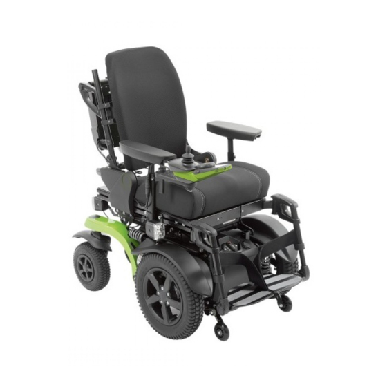
Page 9: Product Overview
Module carrier for control electronics Caster wheel splash guard Side panel with arm support Motor with brake release Back support angle adjustment (power adjust Suspension ment) Rear lights Front light Drive wheel splash guard Leg support Drive wheel Seat cushion Anti-tipper Control panel Juvo... - Page 10 Module carrier for control electronics Anti-tipper Side panel with arm support Motor with brake release Back support angle adjustment (power adjust Drive wheel splash guard ment) Rear lights Front light Suspension Leg support Caster wheel splash guard Seat cushion Caster wheel Control panel Juvo...
-
Page 11: Safety
Seat cushion Drive wheel splash guard Control panel 3 Safety 3.1 Explanation of warning symbols Warning regarding possible serious risks of accident or injury. WARNING Warning regarding possible risks of accident or injury. CAUTION Warning regarding possible technical damage. NOTICE Juvo... -
Page 12: General Safety Instructions
► Do not expose the product to any extreme temperatures (e.g. direct sunlight, sauna, extreme cold). NOTICE Use under incorrect environmental conditions Damage to the product due to excessively high or low temperatures ► Only use the product within a temperature range of -15 °C to +40 °C (5 °F to +104 °F). Juvo... -
Page 13: Effects Of Electromagnetic Interference On The Product And On The User
Other types of hand-held devices, such as cordless phones, laptop computers, AM/FM radios, TV sets, CD players, and cassette players, and small appliances, such as electric shavers and hair dryers, so far as we know, are not likely to cause EMI problems to your powered wheelchair. Juvo... -
Page 14: Nameplate And Warning Labels
Safety 3.4 Nameplate and warning labels 3.4.1 Signage on the product The warning signs and nameplates are attached at the following mounting points to the power wheelchair: Juvo... -
Page 15: Nameplate
*** YYYY = year of manufacture; MM = month of manufacture; DD = day of manufacture If the adjacent symbol appears on the nameplate, this indicates the following: The product may not be used as a seat in vehicles for transporting persons with reduced mobility. Juvo... -
Page 16: Warning Labels
A full list of the available modules and accessories is shown on the order form and in the accessories catalogue. For use of the options, see the section "Use". Please note that retrofitting options further reduces the maximum load capacity (user weight + luggage). Juvo... -
Page 17: Accessories From Other Manufacturers
The tyres should be replaced every 2 years regardless of wear and tear. • • When power wheelchairs with PU tyres are parked for long periods, the tyres may become deformed (flat spots). This deformation will go away on its own over time while driving. Juvo... -
Page 18: Preparation For Use
► Programming may only be performed by qualified personnel trained by the manufacturer. The manufacturer of the product and the control unit manufacturer are not liable in case of damage caused by programming which was not performed properly and/or which was not adjusted properly according to the user's abilities. Juvo... -
Page 19: Use
1) Insert the side panel into the side panel holder. 2) Re-tighten the thumb screw on the side panel hold er (see fig. 7, item 1). To make getting in from the side easier or for transportation, the side panels can be removed if needed. Juvo... -
Page 20: Adjusting The Side Panels
Adjusting the armrest to the forearm length 1) Loosen the 2 Allen head screws on the underside of the armrest (see fig. 10, item 2). 2) Push the armrest to the front or back into the desired position. 3) Tighten the 2 Allen head screws. Juvo... -
Page 21: Adjusting The Control Panel Position
3) Tighten the set screws on the bottom of the arm rest. Adjusting the height of the control panel position 1) Loosen the set screw on the height adjustment (see fig. 13, item 2). 2) Adjust the height. 3) Tighten the set screw on the height adjustment. Juvo... -
Page 22: Legrests
Exposed pinch points Crushing, pinching due to incorrect handling ► Do not reach into the danger area with your fingers when folding the legrest or footplates up or down. The legrests can be subsequently adjusted to the user's lower leg length. Juvo... -
Page 23: Backrest
4) Check to ensure the lock is securely engaged by pulling on the backrest. Folding down the backrest 1) Pull on the strap until the locking bolts are free (see fig. 17, item 1). 2) Lay the backrest down on the seat. Juvo... -
Page 24: Adjusting The Back Angle
The modular design of the power wheelchair and the ease with which you can remove the side panels and legrests make it easy to get into and out of the wheelchair from the side or from the front. Users can choose the method for getting into and out of the wheelchair which is most suitable for them. Juvo... -
Page 25: Control Unit
The control panel is divided into the keypad, two LED displays and the joystick. The charging/programming recept acle is on the underside. The control panel is used to switch the power wheelchair on and off, enter driving commands and display the cur rent status of certain functions and components. Juvo... -
Page 26: Buttons And Display Functions
The charging process is indicated by sequential flashing of the LEDs. The driving function is blocked when the battery is charging. Battery indicator on the control panel Display Information Battery is charged Charge battery if possible Battery is charging Sequential indicator Juvo... -
Page 27: Control Panel
Pressing the button briefly increases/decreases the speed level (see Page 46). The acoustic signal changes when the maximum speed level is reached. [Select additional power functions] button Pressing this button toggles through seat function 1 – seat function 2 – no seat function. The selected seat function is indicated by the LEDs. Juvo... - Page 28 Information Battery is charged Charge battery if possible Battery is charging Sequential indicator Battery undervoltage, battery charging urgently required Flashing light Battery overvoltage Flashing light Further LED display functions Further LED display symbols are described in the following sections: Juvo...
-
Page 29: R-Net Control Unit
[Warning flashers on/off] button [Profile/mode] button [Horn] button Rotary multi-selector right: [Increase speed]; left: [Decrease speed] Back side – TEN° control panel Transmitter for infrared signals Charging receptacle Connection for external [Profile] or [Pro file/mode] button (programmable) Connection for external [on/off] button Juvo... -
Page 30: Buttons And Display Functions
Battery indicator [Charge level] – TEN° control panel Symbol Information Constant illumination – battery is charged (blue) Constant illumination – battery partially charged (orange) Slow flashing – charge battery immediately (red) Row of lights illuminating individually – charging in progress (red – orange – blue) Juvo... - Page 31 (bus; train; ship). "Attendant" profile This profile enables operation of an attendant control. The profile image appears automatically on the LCD screen when the attendant control is activated by the attendant. Juvo...
- Page 32 Turtle symbol lights up yellow: automatic speed reduction (e.g. because a seat function was activated) Restricted speed (creep speed) Turtle symbol flashes red: power wheelchair is prevented from driving Temperature warning Thermometer symbol lights up orange: e.g. overheating due to excessive load Juvo...
- Page 33 Emergency stop: severe controller / handheld control unit and/or drive motor mal function (see Page 105) Joystick not in home position when the unit is turned on (see Page 105) Error message with various information notices (see Page 105) Drive-away lock (see Page 48) The control unit has to be restarted (symbol flashing) Juvo...
-
Page 34: Adjustment Possibilities
Further LCD display symbols are described in the following sections: • Section "Drive-away lock" (see Page 48) • Section "Power seat functions" (see Page 61) • Section "Troubleshooting" (see Page 104) 6.6.2.3 Adjustment possibilities The user can change settings on the display: Juvo... - Page 35 See the section "Environmental control via infrared (IR)" (see Page 40) for further information. [Diagnostics] menu item For trained, qualified personnel only. [Exit] menu item Exit the Settings menu by moving the joystick to the right. The display switches to the first driving profile. Juvo...
-
Page 36: Environmental Control Via Bluetooth
Because of the various operating system versions, some steps (searching for a Bluetooth device, adding a Bluetooth device, establishing a connection to the Bluetooth device) can only be described in very general terms. Also use the respective operating system help. To pair with a PC, perform the following steps: Juvo... - Page 37 The details of the steps that follow and the menus that are shown may differ due to the variety of existing Android software versions. Also use the respective Android help. To pair with an Android device (e.g. smartphone, tablet), complete the following steps: Juvo...
- Page 38 → A list of the available devices is displayed. 4) Start the pairing process by selecting a suitable device name, e.g. Tom's iPhone (To scroll through list: joystick front/back; to select registration: joy stick to the right). → The iPhone symbol is displayed (see Fig. at left). Juvo...
-
Page 39: Selecting The Connected Devices
2) Select the device you wish to deactivate from the list of available devices by scrolling (joystick front/back) and confirm your selection by moving the joystick to the right. → The device registration is now displayed with the additional information <Off>. The device can be activated again in the same manner. A new pairing is not required. Juvo... -
Page 40: Operating Mouse Functions On A Pc
The environmental control mode for devices with infrared remote control is retrieved/exited as follows: • Repeatedly pressing the [Profile/mode] button retrieves the profiles and operating modes in succession (see Page 30; dependent on programming). • When "IR Menu" mode is reached, the programmed devices can be controlled in the home environment. Juvo... -
Page 41: Learning And Assigning Ir Codes
LCD display in "Settings" menu – TEN° control panel Display Information Retrieve the "Settings" menu by pressing and holding the [Warning flashers on/off] button on the TEN° control panel. Then select the [IR Setup] menu item within the menu. Juvo... -
Page 42: Activating And Deactivating Ir Codes
Once an IR code is deactivated, it no longer appears in the user menu. The corresponding command (e.g. [Volume down]) can no longer be transmitted or executed. • If an IR code is activated, it appears in the user menu. The corresponding command (e.g. [Volume down]) can be transmitted and executed. Juvo... -
Page 43: Driving Functions
Use of elevators, lifting platforms Risk of tipping, collision with persons or nearby objects due to incorrect parking ► Always turn the power wheelchair control unit off when using elevators or lifting platforms. ► Make sure that the brake is engaged. Juvo... -
Page 44: Driving Notes
• Avoid jumping down from steps. • Do not lean out of the wheelchair while crossing obstacles. • Only cross railway systems and railway tracks in the designated areas. Juvo... -
Page 45: Switching On And Off
Falling, tipping over, collision with persons or nearby objects due to lack of inspection ► Ensure that the brake release lever is in the driving position every time before you drive (see Page 50). ► Check the control unit display to ensure that the brakes are operational and functional (see Page 105). Juvo... -
Page 46: Selecting The Speed Levels
Selected speed level = 2 (TEN° control panel) 6.7.5 Driving WARNING Driving on unsuitable surfaces Risk of falling or tipping over due to operator error ► Do not operate the power wheelchair on very smooth surfaces (e.g. icy surfaces) or very rough surfaces (e.g. gravel or rubble). Juvo... -
Page 47: Range
Driving conditions (e.g. terrain profile, condition of surface) • Charging method • Type and number of power options • Overall weight of the wheelchair with selected equipment • Use of power options • Body weight of user • Tyres (air pressure, tyre tread depth) Juvo... -
Page 48: Anti-Tipper
Deactivating the drive-away lock When the unit is turned on, the [Charge level] LED display is off and the [Selected speed level] LED indicator is in sequential indicator mode. 1) Push the joystick all the way forward until a beep sounds. Juvo... -
Page 49: R-Net Control Unit
Troubleshooting The drive-away lock remains active if the joystick is not moved correctly. 1) Turn the control unit off in order to deactivate the drive-away lock again. 2) Turn the power wheelchair on. 3) Deactivate the drive-away lock again. Juvo... -
Page 50: Adjusting The Driving Characteristics
→ After switching the control device on: The control device recognises that the brake has been released and deactivates the driving function. → A warning appears on the control panel. Enabling/activating the brake 1) If needed: Turn the control device off. Juvo... - Page 51 → A warning appears on the control panel. Enabling/activating the brake 1) If needed: Turn the control device off. 2) Push the brake release lever up (see fig. 40, item 2). 3) Switch on the control device. → The driving function is activated. Juvo...
-
Page 52: Batteries/Charging Process
Batteries reach their full capacity only after approx. 20 charge cycles. Only if the full capacity of the batteries has been reached can the power wheelchair achieve the stated range. Juvo... -
Page 53: Battery Charger
Risk of electric shock due to contact with live components ► Do not touch live electrical components. The battery charger and its cables are live when the charger is on. ► Do not remove any insulation or protective covers. Juvo... - Page 54 4) Turn the battery charger off and pull the plug out of the mains socket when the charging process is complete. 5) Disconnect the charging plug from the control pan 6) Turn the power wheelchair control unit on. The power wheelchair is ready to use. Juvo...
-
Page 55: Seat
► The seat and back support upholstery as well as seat cushions, padding and covers fulfil the normative requirements for flame resistance. However, they may still ignite if fire is handled improperly or negligently. ► Keep away from all ignition sources, especially lit cigarettes. Juvo... -
Page 56: Seat Type
The product is equipped with a VAS seat (Variable Adjust Seat). This seat type allows the technician to quickly vary the seat depth, seat and back width, and centre of gravity settings. 6.10.3 Contoured pads The contoured pads provide the user with good lateral support. Juvo... -
Page 57: Taking Off And Putting On The Covers
3) Pull the open end of the incontinence cover up and lay it onto the foam pad (top right). 4) Pull the overhanging end of the incontinence cover down and close it on the underside of the foam pad (bottom). 5) Put on the cover. Juvo... -
Page 58: Cleaning The Covers
Large openings in the back shells provide for a low weight and easy handling. Detailed information regarding use, cleaning and main tenance can be found in the included instructions for use. Juvo... -
Page 59: Seat Cushion
3) Release the adjustment lever and let it engage. The adjustment lever is in a safe position if it engages audibly and has returned to its initial position. Adjusting the headrest The height and tilt angle of the headrest are adjustable. Juvo... -
Page 60: Use
The head support or head/neckrest stabilises and guides the user's head. It has been mounted to the mounting kit for head/neckrests by qualified personnel. Detailed information regarding use, maintenance and repair can be found in the included instructions for use. Juvo... -
Page 61: Power Seat Functions
► Observe the following guidelines: at maximum load capacity, 10 seconds of activation time must be followed by approx. 90 seconds of idle time. The power seat functions are considered independently of the driving function for this purpose. ► Only activate the power seat functions if no fault or error is present. Juvo... -
Page 62: Power Seat Height Adjustment
The speed is decreased when the seat is raised. This is indicated on the control panel as follows: VR 2 control unit Display Information Restricted speed (creep speed) INFORMATION: The [Selected speed level] LED display flashes. Juvo... -
Page 63: Power Seat Tilt
(see Page 67). The power seat tilt function allows the seat to be tilted by up to 45°, for example to relieve pressure (with centre of gravity shift). The seat can be tilted back continuously to the spe cified angle. Juvo... -
Page 64: Power Back Angle Adjustment
► Observe the instructions for use in the sections "Controlling power seat functions" (see Page 66) and "Joy stick functions" (see Page 67). The power back angle adjustment feature enables the backrest to be tilted up to 30°. The backrest can be tilted back continuously to the angle specified. Juvo... -
Page 65: Power Legrests
The legrests can be operated individually or at the same time, depending on the configuration. The footrests can be flipped up to increase the entry and exit area. In addition, the electrically adjustable legrests can be lifted up and out of their brackets (item 1). Juvo... -
Page 66: Controlling Power Seat Functions
(see the following section "Joystick functions"). The driving func tion is not available at this time and the speed level indicator switches off. • Once a seat function is activated, it is adjusted by moving the joystick forward or backward. Juvo... -
Page 67: Joystick Functions
Forward: Seat slowly tips forward to a horizontal position Power back angle adjustment Back: Back support tilts backward Forward: Back support tilts forward Power leg support left Back: The left leg support moves up Forward: The left leg support moves down Juvo... -
Page 68: Manual Seat Functions
2) Move the legrest to the desired position. 3) Let go of the release lever. → The legrest is adjusted. 6.13 Lap belt The lap belt provides additional stabilisation and prevents the user from sliding out of the seat. Juvo... -
Page 69: Adaptation
6) Release the respective half of the buckle. 7) Verify the adjustment. WARNING! The lap belt has to fit closely but not too tightly so the user is not injured. It should be possible to slide two fingers com fortably between the strap and thigh. Juvo... -
Page 70: Use
• Allow the belts to air dry. Ensure that the belts and pads are completely dry before installation. • Do not expose the belts to direct heat (e.g. sunshine, stove or radiator). • Do not iron or bleach the belts. Juvo... -
Page 71: Control Unit Accessories
The LCD monitor also serves as the interface to the supplied special control (see Page 75). Important displays on the LCD monitor Display Information Programmed driving profile (e.g. driving profile 1: "Drive") 11:17 Drive Power seat height adjustment (optional) 11:17 Seathigh Power seat tilt (optional) 11:17 Tilt Juvo... -
Page 72: Control Panel For Attendant
Functional overview The attendant uses the attendant control to operate the driving function and the power seat functions. The module is connected in conjunction with the control panel or as a separate input device. Juvo... -
Page 73: R-Net Attendant Control
The attendant uses the attendant control to operate the driving function and the power seat functions. The module is connected in conjunction with the control panel or as a separate input device. The module is connected in combination with the separate LCD monitor and special control (if any). Juvo... - Page 74 > "Drive"). The joystick is used to navigate within the operating modes (see above). [Select speed level] button Pressing the button increases/decreases the speed level. The acoustic signal changes when the maximum speed level is reached. [Selected speed level] LED display The LEDs show the currently selected speed level (1–5). Juvo...
-
Page 75: Adapter Cable For Piko Button
► Prior to initial use, practise handling the special control on level, open ground and under the supervision of appropriately trained attendants. CAUTION Extreme temperatures Hypothermia or burns through contact with components, failure of components ► Do not expose the product to any extreme temperatures (e.g. direct sunlight, sauna, extreme cold). Juvo... -
Page 76: Safety Requirements For Operation
► Maintenance work on the power wheelchair may only be completed by personnel authorised and trained by Ottobock. 6.15.1.4 Effects of electromagnetic interference on the product and on the user INFORMATION Also note the safety instructions in the main "Safety" section regarding this topic (see Page 13). Juvo... -
Page 77: Requirements For The User
Severe injuries due to falling, tipping over, collision of the wheelchair ► Check the proper condition of the on/off switch and user switch safety devices prior to every use. ► Only use the special controls if the on/off switch and user switch are functioning. Juvo... -
Page 78: General
(on the right in the illustration). The joystick has been mounted on a chin swivel arm. This allows the power wheelchair to be controlled using the chin. The qualified personnel programmed the movement ranges according to the specific abilities of the user. Juvo... -
Page 79: Joystick Commands
Cruise: Joystick movement accelerates the wheelchair and driving continues at the speed reached when the joystick is released. Both operating modes can be programmed either for driving forwards, or for driving forwards and in reverse. The Latched drive mode is displayed on the TEN° control panel using the symbol shown at left. Juvo... -
Page 80: User Switch
These buttons are used with the following functions: • Forward • Reverse • Right • Left 6.15.4.2 1-button control (scan function) 6.15.4.2.1 Drive mode The sampling rate in Drive mode can be programmed by the qualified personnel to adjust to the user's abilities. Juvo... -
Page 81: 3-Button Control
Scroll down in list Right Turn right Select menu item Left Turn left *) Sequence mode can also be set for menu selection depending on programming. The menu entries can be scrolled through here by pressing the user switch. Juvo... -
Page 82: 4-Button Control
Pressing the user switch while driving triggers an emergency stop. 6.15.4.4.1 User switch Operating with user switch When the LCD monitor (Omni module) is used as part of the special control, the qualified personnel may also have connected a separate user switch. Juvo... -
Page 83: Sip And Puff Control
Menu mode, which can then be operated using sip and puff commands as shown in the above table. • Issuing two sip or puff commands in quick succession (the time can be programmed) simulates a brief press ing of the user switch and switches to Menu mode. Juvo... -
Page 84: Drive Mode
The swivel arm is operated by installing what is known as a satellite switch. 6.15.6.1 Functions of the satellite switch The satellite switch is mounted on the right or left side. The satellite switch has the following functions: Juvo... -
Page 85: Operating The Swivel Unit
Further information: see Page 40. INFORMATION Please note: The name of the mode for controlling household devices has been designated "I/O Module 1" at delivery. The name can be individually modified by the qualified personnel prior to handover to the user. Juvo... -
Page 86: Additional Options
6.16.1 Control panel holder Swing-away control panel holder The control panel holder makes it possible to drive the power wheelchair under a table or closer to an object. The control panel holder can be rotated up to the armrest. Juvo... -
Page 87: Lighting
If the front lighting has been disconnected from the holder, it can simply be reinserted in the prior position (see fig. 78, right). When connecting the lights, make sure there are no for eign objects on the magnets. The lighting angle is secured by latches. Juvo... -
Page 88: Lighting (Not Intended For Road Traffic)
► Have the basic settings of the belt system checked regularly. Adjustments may be required due to the growth of the user or because of changes in the course of the disease. Small length adjustments of the belt by the user or an attendant (e.g. for clothing of different thickness) are pos sible. Juvo... -
Page 89: Use
► Do not leave the user unsupervised if the cognitive abilities of the user could lead to unintentional opening of the belt system. ► Information about subsequent acquisition and mounting is provided by the qualified personnel that handed the product over to you. Juvo... -
Page 90: Caster Wheel Swivel Lock
This could result in a high mechanical load on the caster wheel swivel lock and thereby to a defect. INFORMATION: Clean the caster wheel swivel lock bolt if it gets dirty. Juvo... -
Page 91: Spring-Mounted Caster Wheel Swing Arm
The spring elements on the caster wheel swing arms increase driving comfort, especially when driving on rough terrain. They also improve traction. The spring elements on the front and rear caster wheel swing arms improve driving comfort, especially when driving on rough terrain. They also improve traction. Juvo... -
Page 92: Mechanical Track Stabiliser
► Do not pinch the user when sliding in the product. CAUTION Collisions while driving Crushing or pinching by the tray ► Please note that the user may be crushed by the tray in the event of a collision. Avoid collisions. Juvo... -
Page 93: Using The Product
CAUTION! The user must not get pinched by the tray. Ensure that the user's arms can rest on the tray and that the front, round cutout does not press on the user's body. 6) Firmly engage the clamping lever on the swivel mechanism. Juvo... -
Page 94: Cleaning
If this is not possible, then the seat or seat back must not be adjusted too far back. The luggage carrier can be used to mount add-on medical devices or to store luggage. The luggage carrier can be removed if required. Juvo... -
Page 95: Curb Climbing Assist
USB connection at the same time. The external power supply is used to charge or operate external devices such as mobile phones, laptops or oxygen units. The type of power supply is embossed in the cover cap. The sides can be chosen as desired. Juvo... -
Page 96: Hand Heater
► For more information please visit the www.iata.org website. The manufacturer recommends contacting the airline directly before every flight to obtain information regarding special transport regulations. ► Use the SSR (special service request) codes to describe the type of limited mobility if necessary. You can for example research these on the Internet. Juvo... -
Page 97: Reducing The Transportation Size
3) Remove the legrests (see Page 22). Preparing for transport 1) Fold the backrest forward and onto the seat surface (see Page 23). 2) Remove the side panels (see Page 19). Place the side panel with control panel on the seat. 3) Remove the legrests (see Page 22). Juvo... -
Page 98: Preparing For Transport
To do so, use the eyebolts on the frame (see fig. 97, right) and the opposite caster wheel swing arms (see fig. 97, left). INFORMATION: Place respectively 2 x one belt loop around each caster wheel swing arm in the marked area. Juvo... -
Page 99: Use In Vehicles For Transporting Persons With Reduced Mobility
"Transporting persons with reduced mobility", order number 646D158. 2) Turn the control device off (see Page 45). 3) Verify brake locking. Engage the brakes if needed (see Page 50). 4) Apply the attachment straps (see below). Juvo... - Page 100 ► Stow all dismantled components securely in the vehicle for transporting persons with reduced mobility. ► Please note that certain settings on the product exclude the use of the product in a vehicle for transporting persons with reduced mobility. Juvo...
-
Page 101: Prohibited Use
► To avoid contamination with germs, clean seat cushions and back upholstery whenever they get soiled. ► Disinfect the product regularly. ► Use a cloth or sponge for cleaning. ► To avoid corrosion, do not use any aggressive cleaning agents or solvents. ► Check the driving behaviour of the product after cleaning it. Juvo... -
Page 102: Cleaning
Inform the qualified personnel promptly for the rectification of defects. • This also applies if loose, worn, bent or damaged components, cracks in the frame or broken frame compon ents are identified. Juvo... -
Page 103: Maintenance Intervals
Check arm support for damage Gas compression Visual inspection for scratches and oil leaks on the pis spring or actuator ton rod Product Check the legibility and completeness of all labels and markings on the product Juvo... -
Page 104: Repair
► Inform the qualified personnel immediately. 7.4.1 Types of notifications Warning A warning indicates a status or malfunction of one or several components of the power wheelchair. The function of components without errors is not restricted. Juvo... -
Page 105: Procedure For Warnings And Error Messages
Move the joystick to the home posi ition when the unit is tion before switching the unit on turned on Controller fault Defective controller Check all connections Brake release Open brake release Check motor brakes Check connection to the controller Juvo... - Page 106 (None) Battery undervoltage Battery deep dis Charge as soon as charge possible High Battery (None) Battery overvoltage Voltage too high Continue driving slowly Loose battery con tacts Check cabling / plug connections; if error message persists, contact specialist dealer Juvo...
- Page 107 Overtemp. (Lamps) (None) Temperature on the e.g. defective plug Cool down phase light circuit on the connections Check plug connec controller too high Defective lamp tions and cable to light case recur rence: contact spe cialist dealer Juvo...
- Page 108 JS Static Timeout (None) Joystick holding time Excessive joystick Switch control unit exceeded deflection detected off/on (control unit stops error persists: drive system to pre replace control panel vent potential dam joystick; contact age to the motors) specialist dealer Juvo...
-
Page 109: Attendant Control Error Overview
(joystick) and the con trol panel/controller R-Net attendant control Flashing LED Error/warning Cause Possible measure Control unit fault Fault in the control unit Read error on the control panel and take corresponding action (see "Wheelchair control unit error over view" table) Juvo... -
Page 110: Behaviour In Case Of Breakdowns
The product meets the requirements under the RoHS Directive 2011/65/EU of the European Parliament and of the Council of 8 June 2011 on the restriction of the use of certain hazardous substances in electrical and electronic equipment. Juvo... -
Page 111: Warranty
Equipped with mobility base 1 + VAS seat from 115 kg (from 253.5 lbs) Equipped with mobility base 2 + VAS seat from 130 kg (from 286.5 lbs) * The specified weights vary according to the accessories and selected model. Load capacity Maximum load capacity See nameplate for precise information (User weight + luggage) Juvo... - Page 112 Dimensions – Recaro® seat Effective seat depth 380–560 mm (15"–22.8") Seat width* Inside: 320–340 mm (12.6"–13.4") Outside: 450–480 mm (17.7"–18.9") 400–560 mm (15,7"–22") Seat height** Lower leg length 280–540 mm (11"–21.2") Back height 620 mm (24.4") * Inner seat width = effective seat width Juvo...
- Page 113 Caster wheel tyre size 9"/10" Drive wheel tyre size 14" * Might be larger due to seat width adjustment. Overall width +180 mm in the assembled state. ** Weight of the heaviest component Dimensions and weights (rear-wheel drive; mobility base = size 1) Juvo...
- Page 114 * Might be larger due to seat width adjustment. Overall width +180 mm in the assembled state. ** Weight of the heaviest component Dimensions and weights (mid-wheel drive; mobility base = size 1) Arm support height (telescoping arm sup port) Juvo...
- Page 115 * Might be larger due to seat width adjustment. Overall width +180 mm in the assembled state. ** Weight of the heaviest component Transportation size (storage length x storage width x storage height) Storage length 1100 mm (43.3") Storage width Minimum: 596 mm (23.5"); maximum: 630 mm (24.8") Juvo...
- Page 116 PU tyres Driving data (rear-wheel drive/front-wheel drive) Speed* See nameplate for precise information: 6 km/h (3.7 mph); 7.2 km/h (4.4 mph); 10 km/h (6.2 mph); 14 km/h (8.7 mph) Nominal incline (base model)** 10° (17.5 %) Dynamic stability – uphill*** 10° (17.5 %) Static stability – uphill/downhill 10° (17.5 %) Juvo...
- Page 117 * The specified range was determined under defined conditions according to ISO 7176-4. In practice the range can be reduced by up to 50%. For information on this, see the section "Range" in the instructions for use (user). Electrical system* IP protection rating (according to DIN EN IP44 60529) Operating voltage 24 V DC Lighting Juvo...
- Page 118 Control device Model R-Net (controller in combination with TEN° control panel) Max. output current per motor 90 A (1 x integrated seat function, direct control without actuator mod ule) Force for operating the joystick on the 1.6 N standard control panel Juvo...
-
Page 119: Appendices
60 mm (2.4") under the foot rest for going for ward at the end of the slope Maximum inclination angle on which the 6° (dynamic stability in all directions) wheelchair will remain stable 9° (static stability in all directions, also when wheel lock engaged) Juvo... - Page 120 Juvo...
- Page 121 Juvo...
- Page 122 Juvo...
- Page 123 · www.ottobock.de 143441 Moscow Region/Krasnogorskiy Rayon info@ottobock.com.co · www.ottobock.com.co Russian Federation Otto Bock Healthcare Products GmbH Otto Bock de Mexico S.A. de C.V. T +7 495 564 8360 · F +7 495 564 8363 Brehmstraße 16 · 1110 Wien · Austria Prolongación Calle 18 No. 178-A info@ottobock.ru · www.ottobock.ru F +43 1 5267985...
- Page 124 Ihr Fachhändler | Your specialist dealer Otto Bock Mobility Solutions GmbH Lindenstraße 13 · 07426 Königsee-Rottenbach/Germany www.ottobock.com...
Need help?
Do you have a question about the Juvo and is the answer not in the manual?
Questions and answers