Table of Contents
Advertisement
Quick Links
Download this manual
See also:
Operating Manual
Advertisement
Table of Contents

Related Manuals for Humminbird 787C2


Summary of Contents for Humminbird 787C2
- Page 1 531476-1_A - 787c2_Eng.qxd 11/22/2005 3:20 AM Page 1 787c GPS Chartplotter 787c GPS Chartplotter Operations Manual Operations Manual 531476-1_A...
-
Page 2: Table Of Contents
Thank you for choosing Humminbird®, America's #1 name in fishfinders. Humminbird® has built its reputation by designing and manufacturing top-quality, thoroughly reliable marine equipment. Your Humminbird® is designed for trouble-free use in even the harshest marine environment. In the unlikely event that your Humminbird® does require repairs, we offer an exclusive Service Policy - free of charge during the first year after purchase, and available at a reasonable rate after the one-year period. - Page 3 GPS Diagnostic View ........
- Page 4 531476-1_A - 787c2_Eng.qxd 11/22/2005 3:20 AM Table of Contents Bottom View............... . . 65 Zoom Width .
-
Page 5: How Sonar Works
U.S. by our authorized International Distributors. To obtain a list of authorized International Distributors, please visit our website at www.humminbird.com or contact our Customer Resource Center at 1-800-633-1468 to locate the distributor nearest you. -
Page 6: Dualbeam Plus™ Sonar
531476-1_A - 787c2_Eng.qxd 11/22/2005 3:20 AM The sound pulses are transmitted at various frequencies depending on the application. Very high frequencies (455 kHz) are used for greatest definition but the operating depth is limited. High frequencies (200 kHz) are commonly used on consumer sonar and provide a good balance between depth performance and resolution. -
Page 7: Quadrabeam™ Sonar (With Optional-Purchase Quadrabeam™ Transducer)
531476-1_A - 787c2_Eng.qxd 11/22/2005 3:20 AM QuadraBeam™ Sonar (with optional-purchase QuadraBeam transducer) Your 700 Series™ Fishing System also supports QuadraBeam™ sonar with the purchase of an additional QuadraBeam™ QuadraBeam™ sonar provides an extremely wide 90° area of coverage. QuadraBeam™ starts with two 45° 455 kHz beams for a continuous 90°... -
Page 8: How Gps And Cartography Work
+/- 10 meters, depending on conditions. This means that 95% of the time, the GPS receiver will read a location within 10 meters of your actual position. Your GPS Receiver also uses information from WAAS (the Wide... -
Page 9: What's On The Display
GPSreceiver. A waypoint can be marked at the cursor position for later retrieval and use with a GPS receiver. NOTE: Entries in this view that list (with Temp/Speed or GPS Receiver) are available if either only the information from the GPS receiver will be displayed on the view. -
Page 10: Views
NOTE: Side Beam View and WideSide® View require the purchase of the QuadraBeam transducer for the Side Beam View and the WideSide® transducer for the WideSide® View. You can visit our website at www.humminbird.com to order these accessories online or contact our Customer Resource Center at 1-800-633-1468. -
Page 11: Understanding Sonar History
531476-1_A - 787c2_Eng.qxd 11/22/2005 3:21 AM Understanding Sonar History It is important to understand the significance of the 700 Series™ Fishing System display. The display does NOT show a literal 3-dimensional representation of what is under the water. Each vertical band of data received by the control head and plotted on the display represents something that was detected by a sonar return at a particular time. -
Page 12: Sonar Zoom View
531476-1_A - 787c2_Eng.qxd 11/22/2005 3:21 AM Structure ID® represents weak returns in blue and strong returns in red. WhiteLine® highlights the strongest sonar returns in white, resulting in a distinctive outline. This has the benefit of clearly defining the bottom on the display. Page 22 Sonar Zoom View Sonar Zoom View increases the displayed resolution to separate sonar returns that are... -
Page 13: 200/83 Khz Split Sonar View
531476-1_A - 787c2_Eng.qxd 11/22/2005 3:21 AM 200/83 kHz Split Sonar View Split Sonar View displays sonar returns from the 83 kHz wide beam on the left side of the screen and displays sonar returns from the 200 kHz narrow beam on the right side of the screen. -
Page 14: Screen Snapshot View
531476-1_A - 787c2_Eng.qxd 11/22/2005 3:21 AM Screen Snapshot View When Screen Snapshot is enabled (from the Accessories menu tab), pressing the MARK key creates a saved screen capture (when you have an optional-purchase MMC/SD card installed). Screen Capture View Taking a screen snapshot is a four step process: 1. -
Page 15: Side Beam View (With Optional-Purchase Quadrabeam™ Transducer)
531476-1_A - 787c2_Eng.qxd 11/22/2005 3:21 AM Side Beam View (with optional-purchase QuadraBeam™ transducer) Side Beam View is only available if you have connected a QuadraBeam accessory and when Transducer Select is set to QuadraBeam™ (see Sonar Menu Tab: Transducer Select). The QuadraBeam™ transducer requires a separate purchase. This view shows sonar information from both the left and right 90°... -
Page 16: Bird's Eye View
531476-1_A - 787c2_Eng.qxd 11/22/2005 3:21 AM Bird’s Eye View Bird's Eye View - This view shows a 3-D, perspective view of the track and the chart’s land contour from a point above and behind the boat (the eye point). As the boat turns, the eye point moves to follow the boat. -
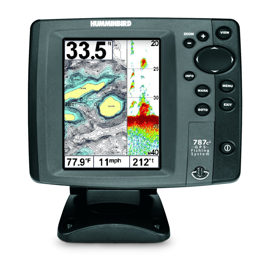
Page 17: Combo View
531476-1_A - 787c2_Eng.qxd 11/22/2005 3:21 AM Combo View Combo View - This view is displayed as a split screen, with Chart View on the left and Sonar View on the right side of the screen. The width of the sonar window can be changed. -
Page 18: Introduction To Navigation
531476-1_A - 787c2_Eng.qxd 11/22/2005 3:21 AM fall of the tides for the 24 hour time period encompassing the date. You can change the date to look at tide information before or after the date displayed by pressing the LEFT or RIGHT cursor key respectively. Press the EXIT key to remove the information box and the cursor bull’s eye will be centered over the tide station position. -
Page 19: Save, Edit Or Delete A Waypoint
531476-1_A - 787c2_Eng.qxd 11/22/2005 3:21 AM Save, Edit, or Delete a Waypoint Save your current position as a waypoint: On any view, press the MARK key to save the current position of the boat as a waypoint. Save the cursor position as a waypoint: On the Chart or Combo view, use the Cursor key to designate the position you want to save as a waypoint. -
Page 20: Add A Waypoint Target Or Trolling Grid
531476-1_A - 787c2_Eng.qxd 11/22/2005 3:21 AM Add a Waypoint Target or Trolling Grid Waypoint Target Add or Remove a Waypoint Target: From the Waypoints submenu, select Target and press the RIGHT Cursor key to display a list of waypoints. Select the waypoint you want to target. -
Page 21: Save Or Clear A Current Track
531476-1_A - 787c2_Eng.qxd 11/22/2005 3:21 AM Save or Clear a Current Track Save the current track: From the Navigation X-Press menu, select Save Current Track and press the RIGHT Cursor key. The track will remain on the display, but will change from black to gray. -
Page 22: Info Key
Navigation is not affected by the Screen Snapshot feature. Also, if Screen Snapshot is enabled but there is no GPS receiver connected, pressing the MARK key will capture the screen image and display an error saying that a GPS position fix is required to create a waypoint. -
Page 23: Zoom (+/-) Key
Series™ Fishing System Accessories in this manual, as well as your accessory's Operations Manual for additional details. NOTE: Accessories to enable WeatherSense® and the SmartCast®Wireless Sonar Link require separate purchases. You can visit our website at www.humminbird.com or contact our Customer Resource Center at 1-800-633-1468 for additional details. Page 44... -
Page 24: The Menu System
531476-1_A - 787c2_Eng.qxd 11/22/2005 3:21 AM The Menu System The menu system is divided into easy-to-use menu modules. The main components of the menu system are: Start-Up Options Menu - Press the MENU key during the power up sequence to view the Start-Up Options menu. -
Page 25: Start-Up Options Menu
The following screens are displayed in turn when you press the VIEW button when using System Status: • Self Test • Accessory Test • GPS Diagnostic View. Exit System Status by powering your Fishing System off. Simulator Use the Simulator to learn how to use your 700 Series™... -
Page 26: Self Test
This view also reports the current position, local time and date, and other numeric information. The current GPS Fix Type is reported as No Fix, 2D Fix, 3D Fix, or Enhanced. An Enhanced fix has been augmented using information from WAAS, EGNOS, or MSAS. -
Page 27: Sonar X-Press Menu
WideSide® view. NOTE: Side requires the purchase of the WideSide® transducer. You can visit our website at www.humminbird.com to order this accessory online or contact our Customer Resource Center at 1-800-633-1468. To adjust the Side: 1. -
Page 28: Sensitivity
531476-1_A - 787c2_Eng.qxd 11/22/2005 3:21 AM Sensitivity Sensitivity controls how much detail is shown on the display and will adjust the sensitivity of all sonar frequencies. Increasing the sensitivity shows more sonar returns from small baitfish and suspended debris in the water; however, the display may become too cluttered. -
Page 29: Lower Range
Tab: Transducer Select) and can only be accessed from the WideSide® view. NOTE: The Side Beam Range requires the purchase of the WideSide® transducer. You can visit our website at www.humminbird.com to order this accessory online or contact our Customer Resource Center at 1-800-633-1468. -
Page 30: Bottom Range (Sonar Zoom View Only When Bottom Lock Is On)
531476-1_A - 787c2_Eng.qxd 11/22/2005 3:21 AM Bottom Range (Sonar Zoom view only when Bottom Lock is On) Bottom Range allows you to control how much of the water column, measured up from the bottom, is shown in the Sonar Zoom View. Choose a small value to see low-lying bottom structure or details of the bottom return. -
Page 31: Navigation X-Press Menu
531476-1_A - 787c2_Eng.qxd 11/22/2005 3:21 AM Navigation X-Press Menu (Navigation views only) The Navigation X-Press menu provides access to the settings most frequently used. Press the MENU key once while in the Bird's Eye View, the Chart or the Combo View to access the Navigation X-Press NOTE: Menu choices will vary depending on system settings, such as whether you are currently navigating. -
Page 32: Cursor To Waypoint (Chart Or Combo View Only)
531476-1_A - 787c2_Eng.qxd 11/22/2005 3:21 AM Cursor to Waypoint (Chart or Combo view only) Cursor to Waypoint allows you to quickly move the cursor to any saved waypoint, so that you can locate it or edit it. NOTE This X-Press menu item appears only if you have saved waypoints. -
Page 33: Cancel Navigation (Only When Navigating)
531476-1_A - 787c2_Eng.qxd 11/22/2005 3:21 AM Cancel Navigation (only when Navigating) Cancel Navigation discards the current route and exits Navigation Mode. This menu choice will only appear when you are currently navigating a route. This will not delete a previously-saved route. To Cancel Navigation: 1. -
Page 34: Waypoint [Name] (Most Recently-Created Waypoint)
531476-1_A - 787c2_Eng.qxd 11/22/2005 3:21 AM Waypoint [Name] (Most recently-created waypoint) Waypoint [Name] allows you to view the waypoints submenu for the most recently created waypoint. NOTE: You must have pressed the MARK key at least once since you last powered up the fishfinder for this menu choice to appear. -
Page 35: Sonar Menu Tab
531476-1_A - 787c2_Eng.qxd 11/22/2005 3:21 AM Sonar Menu Tab Press the MENU key twice to access the Main Menu System and then press the RIGHT Cursor key to select the Sonar tab. NOTE: Menu choices will vary depending on system settings such as whether the unit is set for Advanced User mode or what transducer is currently selected. -
Page 36: Fish Id+ Tm
531476-1_A - 787c2_Eng.qxd 11/22/2005 3:21 AM Fish ID+ Fish ID+ uses advanced signal processing to interpret sonar returns, and will display a Fish Symbol when very selective requirements are met. When a fish is detected, a fish icon and its depth are displayed above the return that has been classified as being a fish. -
Page 37: Bottom View
531476-1_A - 787c2_Eng.qxd 11/22/2005 3:21 AM Bottom View Bottom View selects the method used to represent bottom and structure on the display. Structure ID® represents weak returns in blue and strong returns in red. WhiteLine® highlights the strongest sonar returns in white resulting in a distinctive outline. -
Page 38: 455 Khz Balance
Advanced (see Setup Menu Tab: User Mode). NOTE: The 455 kHz Balance requires the purchase of the QuadraBeam™ transducer. You can visit our website at www.humminbird.com to order this accessory online or contact our Customer Resource Center at 1-800-633-1468. NOTE: 455 kHz Balance is particularly useful for adjusting the sensitivity of the 455 kHz sonar returns in the Side Beam View. -
Page 39: Depth Lines (Advanced)
531476-1_A - 787c2_Eng.qxd 11/22/2005 3:21 AM Depth Lines (Advanced) Depth Lines divide the display into four equal sections that are separated by three horizontal depth lines. The depth of each line is displayed along the depth scale. You can either turn Depth Lines On or Off. The Depth Lines menu choice is available when User Mode is set to Advanced (see Setup Menu Tab: User Mode). -
Page 40: Noise Filter (Advanced)
531476-1_A - 787c2_Eng.qxd 11/22/2005 3:21 AM Noise Filter (Advanced) Noise Filter adjusts the sonar Noise Filter to limit interference on the display from sources such as your boat engine, turbulence, or other sonar devices. The Noise Filter menu choice is available when User Mode is set to Advanced (see Setup Menu Tab: User Mode). NOTE: The Off setting removes all filtering;... -
Page 41: Navigation Menu Tab
531476-1_A - 787c2_Eng.qxd 11/22/2005 3:21 AM Navigation Menu Tab Press the MENU key twice to access the Main Menu System, then press the RIGHT cursor key to select the Navigation tab. NOTE: Menu choices will vary depending on system settings. Navigation Menu Tab Page 80 submenu. -
Page 42: Saved Tracks
531476-1_A - 787c2_Eng.qxd 11/22/2005 3:21 AM Saved Tracks Saved Tracks allows you to view the Saved Tracks submenu. To view the Saved Tracks Submenu: 1. Highlight Saved Tracks on the Navigation main menu. 2. Use the RIGHT 4-WAY Cursor Control keys to view the Saved Tracks submenu. Saved Tracks Submenu The Saved Tracks Submenu contains the following menu choices: Edit allows you to select a previously-saved track and edit its name, whether it is visible... -
Page 43: Routes
531476-1_A - 787c2_Eng.qxd 11/22/2005 3:21 AM Routes Routes allows you to view the Routes submenu. To view the Routes Submenu: 1. Highlight Routes on the Navigation main menu. 2. Use the RIGHT 4-WAY Cursor Control keys to view the Routes submenu. Routes Submenu The Routes Submenu contains the following menu choices: Create allows you to create a new, empty route and add waypoints to it immediately. -
Page 44: Trackpoint Interval
531476-1_A - 787c2_Eng.qxd 11/22/2005 3:21 AM Trackpoint Interval Trackpoint Interval allows you to select the time period between trackpoints. The current track can only contain up to 20000 trackpoints, so longer time periods cause the track to extend back further in time, but will be less detailed. -
Page 45: Export All Nav Data (Advanced)
531476-1_A - 787c2_Eng.qxd 11/22/2005 3:21 AM Export All Nav Data (Advanced) Export All Nav Data allows you to export all saved Tracks, Waypoints and Routes to an MMC/SD card. The Export All Nav Data menu choice is only available when User Mode is set to Advanced (see Setup Menu Tab: User Mode). -
Page 46: Chart Detail Level
531476-1_A - 787c2_Eng.qxd 11/22/2005 3:21 AM Chart Detail Level Chart Detail Level allows you to select how much chart detail you want displayed on the Navigation Views. Basic shows land areas, ports, obstructions and restricted areas. Navigation shows navaids, landmarks, ferryways and navigation routes in addition to the Basic information. -
Page 47: Set Simulation Position (Advanced)
531476-1_A - 787c2_Eng.qxd 11/22/2005 3:21 AM Set Simulation Position (Advanced) Set Simulation Position allows you to set the position of the boat used in the Simulator. The Set Simulation Position menu choice is only available when User Mode is set to Advanced (see Setup Menu Tab: User Mode). -
Page 48: Alarms Menu Tab
531476-1_A - 787c2_Eng.qxd 11/22/2005 3:21 AM Alarms Menu Tab From any view, press the MENU key twice to access the Main Menu System. The Alarms tab will be the default selection. NOTE: When an alarm is triggered, you can silence it by pressing any key. -
Page 49: Low Battery Alarm
531476-1_A - 787c2_Eng.qxd 11/22/2005 3:21 AM Low Battery Alarm Low Battery Alarm sounds when the input battery voltage is equal to or less than the menu setting. The battery alarm will only sound for the battery that is connected to the 700 Series™ Fishing System. The Low Battery Alarm should be set to warn you when the battery voltage drops below the safety margin that you have determined. -
Page 50: Drift Alarm
531476-1_A - 787c2_Eng.qxd 11/22/2005 3:22 AM Drift Alarm Drift Alarm sounds when the boat has exceeded the distance from the boat’s anchored position, based on the menu setting. Drift Alarm allows you to set the size of a perimeter around the boat’s anchored position; if the anchored boat drifts outside of that perimeter, the Drift Alarm will sound. -
Page 51: Units - Depth
Units - Distance selects the units of measure for all distance- related readouts, and will appear in the menu if a Temp/Speed Accessory is connected and the paddlewheel has moved at least once, or if the GPS Receiver is connected. To change the Units - Distance setting: 1. -
Page 52: Triplog Reset
Triplog Reset resets the Triplog to zero, and will appear in the menu if a Temp/Speed Accessory is connected and the paddlewheel has moved at least once, or if the GPS Receiver is connected. The Triplog provides the following information: timer for elapsed time, distance traveled since last reset, and average speed. -
Page 53: Depth Offset (Advanced)
Local Time Zone (Advanced) Local Time Zone selects your time zone in reference to the time reported by the GPS receiver when Time+Date is selected as a Digital Readout on the Sonar View (see Select Readouts). This menu choice is available only when in Advanced User Mode (see Setup Menu Tab: User Mode). -
Page 54: Daylight Saving Time (Advanced)
531476-1_A - 787c2_Eng.qxd 11/22/2005 3:22 AM Daylight Saving Time (Advanced) Daylight Saving Time adjusts the time display to account for local Daylight Saving Time when Time+Date is selected as a Digital Readout on the Sonar View (see Select Readouts). Selecting On adds one hour to the time display adjusted for your local time zone. -
Page 55: Nmea Output (Advanced)
NMEA Output turns the NMEA* output on or off. This menu choice is available only when in Advanced User Mode (see Setup Menu Tab: User Mode.) NMEA Output should be turned On if you connect the NMEA Output wires of the GPS Receiver cable to another NMEA-compatible device, such as an autopilot. -
Page 56: Views Menu Tab
Accessories Menu Tab (no accessories attached) NOTE: Accessories to enable WeatherSense® and the SmartCast® Wireless Sonar Link require separate purchases. You can visit our website at www.humminbird.com or contact our Customer Resource Center at 1-800-633-1468 for additional details. Accessories Menu Tab... -
Page 57: Using Screen Snapshot
GPS receiver connected, pressing the MARK key will capture the screen image and display an error saying that a GPS position fix is required to create a waypoint. NOTE: The speed of the capture depends on the type of card you use; in general, SD cards capture the screen faster than MMC cards do. -
Page 58: Troubleshooting
11/22/2005 3:22 AM Troubleshooting Before contacting the Humminbird® Customer Resource Center, please read the following section. Taking the time to review these troubleshooting guidelines may allow you to solve a performance problem yourself, and therefore avoid sending your unit back for repair. -
Page 59: Finding The Cause Of Noise
HumminbirdPC™ software downloaded from our website to your PC in order to communicate with the 700 Series™ Fishing System. Be sure to check out our website www.humminbird.com for additional new and exciting accessories to grow your 700 Series™ Fishing System! NOTE: Each accessory requires a separate purchase. -
Page 60: Specifications
Beam (Sonar Beam): A sonar beam is the wide, cone-shaped projection of sound waves formed as sound travels underwater. See Cone Angle. Big Digits View: Big Digits View is a Humminbird® feature that displays the sonar graph and enlarged digital readouts for easy reading from a distance. This is a great tool when monitoring the digital depth is important - such as with higher boat speeds, or when viewing the unit from a distance. - Page 61 Precision sonar beams, such as the Humminbird® 20° beam, have a smaller dead zone than wider sonar beams. Decibel: A Decibel is the measurement for sound pressure level, or "intensity" of the sonar return.
- Page 62 Many Humminbird® units can operate across a very broad depth range (up to 2500 feet) which causes the unit to "look" up to that full depth under some circumstances. Due to the speed of sound in water, this can result in less responsiveness because the unit has to wait for a longer period of time to receive the sonar signal.
- Page 63 Many Humminbird® units operate at up to 40 times per second when in single frequency operation. Due to the limitation of the speed of sound in water, the update rate begins to slow as depth increases to deeper than 50 feet.
- Page 64 (i.e. two fish hanging very close, or a fish hanging very close to structure). Humminbird® findfinders provide a very good 2 1/2 inches of target separation in shallower than 100 feet of depth.
- Page 65 Fix Type: Fix Type indicates whether the GPS receiver is providing 2D fix or 3D fix. A 2D fix requires only three satellites and provides only latitude and longitude. A 3D fix requires four or more satellites, and provides latitude, longitude and altitude.
- Page 66 MMC is a very rugged format suitable for the marine environment, but it is not waterproof. The MMC is removable from Humminbird® products, and can be used in a PC that is equipped with an appropriate card reader. MMC is the same format that many digital cameras use.
- Page 67 Greenwich England. (UTC is equivalent to Greenwich Mean Time (GMT)). To display the correct Local Time in a Humminbird® GPS unit, the user must use the Local Time Zone menu and select the time zone (i.e. EST, CST).
-
Page 68: Contact Humminbird
531476-1_A - 787c2_Eng.qxd 11/22/2005 3:22 AM Page 134 Contact Humminbird® Contact the Humminbird® Customer Resource Center in any of the following ways: By Telephone: (Monday - Friday 8:00 a.m. to 4:30 p.m. Central Standard Time): 1-800-633-1468 By e-mail: (typically we respond to your e-mail within three business days): custserv@johnsonoutdoors.com...
Need help?
Do you have a question about the 787C2 and is the answer not in the manual?
Questions and answers