
Subscribe to Our Youtube Channel
Related Manuals for Humminbird 797c2 GPS Chartplotter


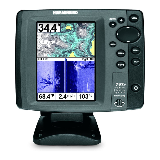
Summary of Contents for Humminbird 797c2 GPS Chartplotter
- Page 1 531519-1_A - 797c2_Man_Covers.qxp 10/24/2006 3:38 AM Page 1 797c GPS Chartplotter 797c GPS Chartplotter Operations Manual Operations Manual 531519-1_A...
- Page 2 Your Humminbird® is designed for trouble-free use in even the harshest marine environment. In the unlikely event that your Humminbird® does require repairs, we offer an exclusive Service Policy - free of charge during the first year after purchase, and available at a reasonable rate after the one-year period.
-
Page 3: Table Of Contents
531519-1_A - 797c2_Man_Eng.qxp 11/6/2006 5:50 AM Page i Table of Contents How Sonar Works Side Imaging Sonar....................3 DualBeam PLUS™ Sonar ..................3 QuadraBeam PLUS™ Sonar ..........4 (with optional-purchase QuadraBeam PLUS™ transducer) Universal Sonar 2 ...................... 5 How GPS and Cartography Work Multi-Media Card (MMC)/SD Slot Software Updates ...................... - Page 4 531519-1_A - 797c2_Man_Eng.qxp 11/6/2006 5:50 AM Page ii Table of Contents Side Beam View ....39 (with optional-purchase QuadraBeam PLUS™ transducer) Bird's Eye View ......................42 Chart View........................ 43 Combo View ......................45 Chart/Side Combo View ..................46 View Orientation ...................... 47 Viewing Cartography Introduction to Navigation Waypoints, Routes and Tracks ................
- Page 5 531519-1_A - 797c2_Man_Eng.qxp 11/6/2006 5:50 AM Page iii Table of Contents Powering Up the Unit The Menu System Start-Up Options Menu Normal Operation ....................68 Simulator ........................ 69 System Status ......................70 Self Test ........................70 Accessory Test......................71 GPS Diagnostic View ....................72 PC Connect ..............
- Page 6 531519-1_A - 797c2_Man_Eng.qxp 11/6/2006 5:50 AM Page iv Table of Contents Navigation X-Press™ Menu (Navigation views only) Waypoint [Name] ........85 (Only with an active cursor on a waypoint) Cursor To Waypoint ............86 (Chart or Combo view only) Save Current Track ....................86 Clear Current Track ....................
- Page 7 531519-1_A - 797c2_Man_Eng.qxp 11/6/2006 5:50 AM Page v Table of Contents Sonar Menu Tab Beam Select ......................99 Fish ID+™ ......................100 Fish ID Sensitivity ....................101 Real Time Sonar (RTS®) Window ................101 Bottom View ......................102 Zoom Width......................102 83 kHz Sensitivity ..................
- Page 8 531519-1_A - 797c2_Man_Eng.qxp 11/6/2006 5:50 AM Page vi Table of Contents Export All Nav Data ................117 (Advanced) Delete All Nav Data ................117 (Advanced) Continuous Navigation Mode ................118 Chart Menu Tab Chart Detail Level ....................120 Map Borders ......................121 Lat/Lon Grid......................
- Page 9 531519-1_A - 797c2_Man_Eng.qxp 11/6/2006 5:50 AM Page vii Table of Contents Units - Speed......................135 User Mode......................135 Language ..................135 (International only) Triplog Reset ......................136 Restore Defaults ....................136 Select Readouts ............137 (Advanced, Sonar view only) Depth Offset ..................
- Page 10 NOTE: Entries in this Table of Contents which list (with PC Connect Cable only) or (with Optional-Purchase QuadraBeam PLUS™ Transducer) or (with Temp/Speed only) require the purchase of separate accessories. You can visit our website at www.humminbird.com to order these accessories online or contact our Customer Resource Center at 1-800-633-1468.
-
Page 11: How Sonar Works
531519-1_A - 797c2_Man_Eng.qxp 11/6/2006 5:50 AM Page 1 How Sonar Works Sonar technology is based on sound waves. The 700 Series™ Fishing System uses sonar to locate and define structure, bottom contour and composition, as well as depth directly below the transducer. Your 700 Series™... - Page 12 531519-1_A - 797c2_Man_Eng.qxp 11/6/2006 5:50 AM Page 2 When all the echoes are viewed side by side, an easy to interpret "graph" of the bottom, fish and structure appears. The sound pulses are transmitted at various frequencies depending on the application. Very high frequencies (455 kHz) are used for greatest definition but the operating depth is limited.
-
Page 13: Side Imaging Sonar
531519-1_A - 797c2_Man_Eng.qxp 11/6/2006 5:50 AM Page 3 Side Imaging Sonar Your 700 Series™ Fishing System uses Side Imaging sonar to provide a wide yet precise survey of a large area of water, including detailed bottom topography and fish-attracting structure orientation. -
Page 14: Quadrabeam Plus™ Sonar (With Optional-Purchase Quadrabeam Plus™ Transducer)
531519-1_A - 797c2_Man_Eng.qxp 11/6/2006 5:50 AM Page 4 QuadraBeam PLUS™ Sonar (with optional-purchase QuadraBeam PLUS™ transducer) Your 700 Series™ Fishing System also supports QuadraBeam PLUS™ sonar with the purchase of an additional QuadraBeam PLUS™ transducer. QuadraBeam PLUS™ sonar provides an extremely wide 90° area of coverage. -
Page 15: Universal Sonar 2
Universal Sonar 2 features new temperature sensing and the performance of DualBeam PLUS™ technology (available with all Humminbird® DualBeam PLUS™ models). An expanded view and greater bottom detail gives you a totally new perspective of the water below, along with optimal sonar performance to help you find fish. - Page 16 531519-1_A - 797c2_Man_Eng.qxp 11/6/2006 5:50 AM Page 6 All satellites broadcast a uniquely coded signal once per second at exactly the same time. The GPS receiver on your boat receives signals from satellites that are visible to it. Based on time differences between each received signal, the GPS receiver determines its distance to each satellite.
-
Page 17: Multi-Media Card (Mmc)/Sd Slot
MMC/SD card. You can obtain software updates from the www.humminbird.com website. -
Page 18: Understanding Side Imaging
531519-1_A - 797c2_Man_Eng.qxp 11/6/2006 5:50 AM Page 8 Understanding Side Imaging It is important to understand how Side Imaging technology produces the display. The images you see on the display are produced using sonar technology. The special transducer produces three distinct beams – one beam facing down and two beams pointing out to the side. - Page 19 Side beams look out 360 feet to each side, with a total side coverage of 720 feet, with a depth limitation of 150 feet, depending on the contour of the bottom. Please see the side imaging sonar tutorial found on www.humminbird.com for a more detailed explanation.
-
Page 20: What's On The Side Imaging Display
531519-1_A - 797c2_Man_Eng.qxp 11/6/2006 5:50 AM Page 10 What’s on the Side Imaging Display Side Imaging displays a number of easily recognizable features that allow for accurate inter composition determines the intensity of the sonar return. For example, rock and gravel provide Upward slopes that face the transducer reflect sonar better than downward slopes that face features on the Side Imaging display that allow for accurate interpretation of bottom contour Topography Changes... - Page 21 531519-1_A - 797c2_Man_Eng.qxp 11/6/2006 5:51 AM Page 11 w for accurate interpretation of bottom contour and structure. For Side Imaging, the bottom k and gravel provide a clearer sonar return than mud and sand because of their relative density. ard slopes that face away from the transducer. You can find a number of easily recognizable n of bottom contour and structure, including the following items: The water column shows the relative depth of the water under the boat at a...
-
Page 22: Side Imaging Technology: How It Works
531519-1_A - 797c2_Man_Eng.qxp 11/6/2006 5:51 AM Page 12 Side Imaging Technology: How It Works Side Imaging sonar uses two very precise sonar beams that are directed to either side of the boat and “illuminate” the bottom contour, structure, and fish, and display results in a “picture-like”... -
Page 23: Side Imaging: On The Water Interpretation
531519-1_A - 797c2_Man_Eng.qxp 11/6/2006 5:51 AM Page 13 Side Imaging: On the Water Interpretation Use the following side imaging examples to help you interpret the side imaging display. Imaging Tips Boat speed: Side imaging is best performed at boat speeds between 2 to 6 mph. - Page 24 531519-1_A - 797c2_Man_Eng.qxp 11/6/2006 5:51 AM Page 14 Creek Channel and New Bridge Piling Creek Channel New bridge pilings Submerged Ravine with Timber Submerged Submerged Ravine Timber Submerged Tree Possible Drop Off...
- Page 25 531519-1_A - 797c2_Man_Eng.qxp 11/6/2006 5:51 AM Page 15 Submerged Bridge: A Closer Perspective Submerged Bridge Submerged Bridge: Alternative Perspective Submerged Bridge...
- Page 26 531519-1_A - 797c2_Man_Eng.qxp 11/6/2006 5:51 AM Page 16 Submerged Standing and Fallen Timber, Plus Bait Fish Bait Fish Standing and Fallen Timber Submerged Swimming Pool Swimming pool...
- Page 27 531519-1_A - 797c2_Man_Eng.qxp 11/6/2006 5:51 AM Page 17 Submerged Barge with Dumped Logs Submerged barge Dumped logs...
-
Page 28: What's On The Sonar Display
531519-1_A - 797c2_Man_Eng.qxp 11/6/2006 5:51 AM Page 18 What’s On the Sonar Display The 700 Series™ Fishing System can display a variety of useful information about the a Depth - water depth; can be set to alarm when the water becomes too shallow. Cursor - available in Freeze Frame and can be positioned in the Sonar View to provide depth of a sonar return and bottom depth below the cursor. - Page 29 531519-1_A - 797c2_Man_Eng.qxp 11/6/2006 5:51 AM Page 19 about the area under and adjacent to your boat, including the following items: High Sonar Intensity Return Bait Ball Thermoclines - layers of water with different temperatures that appear at different depths and different times of the year.
-
Page 30: Views
(i.e. you don’t have to exit the menu to apply the change to the screen). NOTE: Side Beam View requires the purchase of the QuadraBeam PLUS™ transducer. You can visit our website at www.humminbird.com to order this accessory online or contact our Customer Resource Center at 1-800-633-1468. -
Page 31: Side Imaging View
531519-1_A - 797c2_Man_Eng.qxp 11/6/2006 5:51 AM Page 21 Side Imaging View Side Imaging View shows a shadowed right- and left-looking view from the boat as the boat passes over the bottom. See Side Imaging: On the Water Interpretation for more information about interpreting the Side Imaging view. In this view, you can change which side you look at, the sensitivity of the sonar to allow you to see more or less detail, the range of the side beams, the scrolling speed of the chart, and the color scheme of the display, all from the... - Page 32 531519-1_A - 797c2_Man_Eng.qxp 11/6/2006 5:51 AM Page 22 Side Imaging View with Active Cursor Active Cursor Depth Distance to Distance of the Cursor Cursor from and Bearing Centerline to Cursor Side Imaging View with Active SI Zoom SI Zoom Level Magnification Sights Magnification...
-
Page 33: Sonar/Side Combo View
531519-1_A - 797c2_Man_Eng.qxp 11/6/2006 5:51 AM Page 23 Sonar/Side Combo View Sonar/Side Combo View shows regular Sonar information and side imaging sonar information in a combination split screen. You can perform some of the functions for either of these views (see Sonar X-Press™ Menu and Side Imaging X-Press™... -
Page 34: Sonar View
531519-1_A - 797c2_Man_Eng.qxp 11/6/2006 5:51 AM Page 24 Sonar View Sonar View presents a historical log of sonar returns. Depth is always displayed. Readouts for temperature and speed are automatically displayed if the appropriate accessory is connected. The most recent sonar returns are charted on the right side of the window;... -
Page 35: Understanding Sonar History
531519-1_A - 797c2_Man_Eng.qxp 11/6/2006 5:51 AM Page 25 Understanding Sonar History It is important to understand the significance of the display. The display does NOT show a literal 3- dimensional representation of what is under the water. Each vertical band of data received by the control head and plotted on the display represents something that was detected by a sonar return at a particular time. -
Page 36: Freeze Frame And Cursor
531519-1_A - 797c2_Man_Eng.qxp 11/6/2006 5:51 AM Page 26 Freeze Frame and Cursor Freeze Frame - Pressing any arrow on the 4-WAY Cursor Control key will freeze the screen and a cursor will be displayed on the screen. The cursor can be positioned on the display using the 4-WAY Cursor Control key to determine the depth of any sonar return. -
Page 37: Bottom Presentation
531519-1_A - 797c2_Man_Eng.qxp 11/6/2006 5:51 AM Page 27 Bottom Presentation As the boat moves, the unit charts the changes in depth on the display to create a profile of the Bottom Contour. The type of bottom can be determined from the return charted on the display. - Page 38 531519-1_A - 797c2_Man_Eng.qxp 11/6/2006 5:51 AM Page 28 Structure ID® represents weak returns in blue and strong returns in red.
- Page 39 531519-1_A - 797c2_Man_Eng.qxp 11/6/2006 5:51 AM Page 29 WhiteLine® highlights the strongest sonar returns in white, resulting in a distinctive outline. This has the benefit of clearly defining the bottom on the display.
-
Page 40: Sonar Zoom View
531519-1_A - 797c2_Man_Eng.qxp 11/6/2006 5:51 AM Page 30 Sonar Zoom View Sonar Zoom View increases the displayed resolution to separate sonar returns that are very close together, such as those caused by fish suspended close to the bottom or within structure. In Zoom View, the display is split to show a narrow slice of the full range view on the right and the zoomed view on the left. -
Page 41: 200/83 Khz Split Sonar View
531519-1_A - 797c2_Man_Eng.qxp 11/6/2006 5:51 AM Page 31 200/83 kHz Split Sonar View Split Sonar View displays sonar returns from the 83 kHz wide beam on the left side of the screen and displays sonar returns from the 200 kHz narrow beam on the right side of the screen. -
Page 42: Big Digits View
531519-1_A - 797c2_Man_Eng.qxp 11/6/2006 5:51 AM Page 32 Big Digits View Big Digits View provides digital data in a large, easy-to-see format. Depth is always displayed. Readouts for temperature, speed and Triplog information are displayed automatically if the appropriate accessory is connected to the system. -
Page 43: Circular Flasher View
531519-1_A - 797c2_Man_Eng.qxp 11/6/2006 5:51 AM Page 33 Circular Flasher View Circular Flasher View displays Real Time Sonar (RTS®) data in the traditional flasher format. Depth and temperature are always displayed. The digital readouts in the Circular Flasher View cannot be customized. -
Page 44: Snapshot And Recording View
531519-1_A - 797c2_Man_Eng.qxp 11/6/2006 5:52 AM Page 34 Snapshot and Recording View Snapshot and Recording View displays and allows you to view both screen snapshot thumbnails and recording icons captured to an optional-purchase MMC/SD card installed in your unit. In addition, when you are in the Snapshot and Recording View, Start Recording, Stop Recording, Delete Image, Delete All Images, Delete Recording, Delete All Recordings, Pings Per Second, Playback Speed and Stop Playback are added to the X-Press™... - Page 45 531519-1_A - 797c2_Man_Eng.qxp 11/6/2006 5:52 AM Page 35 NOTE: For snapshots and recordings, the indicator bar has several states: during recording, the amount of space remaining on the MMC/SD card is indicated on the status bar. During playback, the amount of time/memory remaining to play is indicated on the status bar. When a snapshot thumbnail is highlighted, the amount of room remaining on the MMC/SD card is indicated.
- Page 46 531519-1_A - 797c2_Man_Eng.qxp 11/6/2006 5:52 AM Page 36 Recording and Playback: From the Snapshot and Recording View, you can use the X-Press™ menu to start and stop recording, and to change the pings per second (which alters the detail level of the recording). Once you are recording already, playing back a recording and screen snapshot viewing are not allowed, and the only Sonar Recording menu choices available in the X-Press™...
- Page 47 531519-1_A - 797c2_Man_Eng.qxp 11/6/2006 5:52 AM Page 37 Recording Slider Bar Name of recording Time and Date recording was started Position where recording was started Current Ping Rate Average Ping Rate Amount of space remaining on card Recording Indicator Amount of Total amount of space and time space on card...
- Page 48 531519-1_A - 797c2_Man_Eng.qxp 11/6/2006 5:52 AM Page 38 and resumes playing when the cursor is removed. Playback is automatically paused when the end of the recording is reached. NOTE: Sonar chart speed is increased during Fast Forward and reversed during Rewind. This may reduce the quality of the sonar image, since at higher speeds, not every sonar return can be processed and displayed.
-
Page 49: Side Beam View (With Optional-Purchase Quadrabeam Plus™ Transducer)
531519-1_A - 797c2_Man_Eng.qxp 11/6/2006 5:52 AM Page 39 Side Beam View (with optional-purchase QuadraBeam PLUS™ transducer) Side Beam View is only available if you have connected an optional-purchase QuadraBeam™ transducer accessory and when Transducer Select is set to QuadraBeam (see Sonar Menu Tab: Transducer Select). The QuadraBeam PLUS™... - Page 50 531519-1_A - 797c2_Man_Eng.qxp 11/6/2006 5:52 AM Page 40 Classic layout: The top portion of the display presents a historical log of sonar returns from the 200 kHz down-looking sonar beam. New information in the down beam panel scrolls from right to left. The bottom portion of the display presents a historical log of sonar returns from the 455 kHz right- and left-looking sonar beams.
- Page 51 531519-1_A - 797c2_Man_Eng.qxp 11/6/2006 5:52 AM Page 41 Slanted layout: This layout presents the two 455 kHz side sonar beams and the 200 kHz down-looking sonar beam as three panels of historical data. This layout is presented as three slanted panels. New information appears on the right, and scrolls to the left.
-
Page 52: Bird's Eye View
531519-1_A - 797c2_Man_Eng.qxp 11/6/2006 5:52 AM Page 42 Bird’s Eye View Bird's Eye View - This view shows a 3-D, perspective view of the track and the chart’s land contour from a point above and behind the boat (the eye point). As the boat turns, the eye point moves to follow the boat. -
Page 53: Chart View
531519-1_A - 797c2_Man_Eng.qxp 11/6/2006 5:52 AM Page 43 Chart View Chart View - This view shows cartography from the built-in UniMap™ or an optional MMC/SD map for the area surrounding your current position. The current track (also known as the position history or breadcrumb trail) showing where the boat has been, along with saved tracks, waypoints, and the current route (when navigating), are overlaid on the chart. - Page 54 531519-1_A - 797c2_Man_Eng.qxp 11/6/2006 5:52 AM Page 44 Chart View with Active Cursor, shown with Optional-Purchase Navionics® Cartography Depth Cartography Map Scale Active Cursor Latitude and Longitude Position of Cursor Distance to the Bearing of Boat Cursor and with Respect Bearing to True North to Cursor...
-
Page 55: Combo View
531519-1_A - 797c2_Man_Eng.qxp 11/6/2006 5:52 AM Page 45 Combo View Combo View - This view is displayed as a split screen, with Chart View on the left and Sonar View on the right side of the screen. The width of the sonar window can be changed. -
Page 56: Chart/Side Combo View
531519-1_A - 797c2_Man_Eng.qxp 11/6/2006 5:52 AM Page 46 Chart/Side Combo View Chart/Side Combo View shows regular chart information and side imaging sonar information in a combination split screen. You can perform some of the functions for either of these views (see Navigation X-Press™ Menu and Side Imaging X-Press™... -
Page 57: View Orientation
531519-1_A - 797c2_Man_Eng.qxp 11/6/2006 5:52 AM Page 47 View Orientation Both Chart and Combo views allow you to choose the orientation of the view. When North-Up orientation is selected, True North is shown at the top of the display. In other words, objects located to the north of the boat are drawn above the boat. - Page 58 531519-1_A - 797c2_Man_Eng.qxp 11/6/2006 5:52 AM Page 48 Zooming: Use the Plus (+) key to Zoom In and the Minus (-) key to Zoom Out showing the cartography at different scales. The scale is indicated on the left side of the display. If you zoom in beyond the available chart data, the display will go into Overzoom mode whereby the last available chart data is amplified to reflect the scale selected.
-
Page 59: Introduction To Navigation
531519-1_A - 797c2_Man_Eng.qxp 11/6/2006 5:52 AM Page 49 before or after the date displayed by pressing the LEFT or RIGHT cursor key respectively. Press the EXIT key to remove the information box and the cursor bull’s eye will be centered over the current station position. The cursor information boxes at the bottom of the display will indicate the distance and bearing to the current station from your present position. -
Page 60: Waypoints, Routes And Tracks
531519-1_A - 797c2_Man_Eng.qxp 11/6/2006 5:52 AM Page 50 Waypoints, Routes and Tracks Waypoints are stored positions that allow you to mark areas of interest or navigation points. Your Fishing System can store up to 3000 waypoints. Waypoints, Routes and Tracks Depth Waypoint Route... -
Page 61: Save, Edit Or Delete A Waypoint
531519-1_A - 797c2_Man_Eng.qxp 11/6/2006 5:52 AM Page 51 Save, Edit, or Delete a Waypoint Save your current position as a waypoint: On any view, press the MARK key to save the current position of the boat as a waypoint. Save the cursor position as a waypoint: On the Chart or Combo view, use the Cursor key to designate the position you want to save as a waypoint. -
Page 62: Navigate To A Waypoint Or Position
531519-1_A - 797c2_Man_Eng.qxp 11/6/2006 5:52 AM Page 52 To make it easier to select a waypoint, select Sort By and press the RIGHT or LEFT Cursor keys to select a sort order: • Name shows the waypoints alphabetically • Time shows the most recently-created waypoint first •... -
Page 63: Add A Waypoint Target Or Trolling Grid
531519-1_A - 797c2_Man_Eng.qxp 11/6/2006 5:52 AM Page 53 Add a Waypoint Target or Trolling Grid Add or Remove a Waypoint Target: From the Waypoints submenu, select Target and press the RIGHT Cursor key to display a list of waypoints. Select the waypoint you want to target. - Page 64 531519-1_A - 797c2_Man_Eng.qxp 11/6/2006 5:52 AM Page 54 Add or Remove a Trolling Grid: From the Waypoints submenu, select Grid and press the RIGHT Cursor key to display a list of waypoints. Select the waypoint to which you want to add the grid. The trolling grid will appear on all of the navigation views, and can be used as a guide when trolling around a waypoint.
-
Page 65: Save, Edit Or Delete A Route
531519-1_A - 797c2_Man_Eng.qxp 11/6/2006 5:52 AM Page 55 Save, Edit or Delete a Route Save the current route: While you are navigating, the current route can be saved. From the Navigation X-Press™ menu, select Save Current Route and press the RIGHT Cursor key. Navigation will continue. Display the Routes submenu: From any view, press the MENU key twice to display the Main Menu System, then use the RIGHT Cursor key to select the Navigation tab. -
Page 66: Save Or Clear A Current Track
531519-1_A - 797c2_Man_Eng.qxp 11/6/2006 5:52 AM Page 56 Save or Clear a Current Track Save the current track: From the Navigation X-Press™ menu, select Save Current Track and press the RIGHT Cursor key. The track will remain on the display, but will change from black to gray. To remove the track completely from the display, see Edit, Delete or Hide Saved Tracks. -
Page 67: Man Overboard (Mob) Navigation
531519-1_A - 797c2_Man_Eng.qxp 11/6/2006 5:52 AM Page 57 Man Overboard (MOB) Navigation As soon as you know that you have a man overboard, you should activate MOB navigation to maximize chances for a successful rescue. MOB navigation allows you create an MOB waypoint to locate the point at which your man went overboard, and the relation of the boat to that point. - Page 68 531519-1_A - 797c2_Man_Eng.qxp 11/6/2006 5:52 AM Page 58 MOB Navigation Position where man fell overboard Elapsed time since Target surrounding MOB was activated MOB waypoint Map Scale Boat’s current position MOB waypoint XTE: Cross Track Error. Distance of Boat from Route BRG - Bearing to DTG - Distance waypoint...
-
Page 69: Key Functions
531519-1_A - 797c2_Man_Eng.qxp 11/6/2006 5:52 AM Page 59 Key Functions Your Fishing System user interface consists of a set of easy-to-use keys that work with various on-screen views and menus to give you flexibility and control over your fishing experience. POWER/LIGHT Key The POWER/LIGHT key is used to turn the Fishing System on and off, and also to adjust the backlight and contrast of the display. -
Page 70: Info Key
531519-1_A - 797c2_Man_Eng.qxp 11/6/2006 5:52 AM Page 60 INFO Key Info - Press the INFO key while in Bird's Eye, Chart or Combo View to display information about objects that are nearest to an active cursor. If the cursor is not active, the following menu will be displayed. -
Page 71: 4-Way Cursor Control Key
531519-1_A - 797c2_Man_Eng.qxp 11/6/2006 5:52 AM Page 61 4-WAY Cursor Control Key The 4-Way Cursor Control Key has multiple functions, depending on the situation: • Use the DOWN or UP arrow keys to select a menu choice from the menu list, then use the LEFT or RIGHT arrow keys to change a menu setting. -
Page 72: Mark Key
531519-1_A - 797c2_Man_Eng.qxp 11/6/2006 5:52 AM Page 62 MARK Key Press the MARK key while in any view to mark the position of a waypoint, either at the current boat location, or, if the Cursor is active, at the current Cursor location. The MARK key only functions if you have the GPS receiver connected, or if you have enabled Screen Snapshot from the Accessories menu tab. -
Page 73: Zoom (+/-) Key
531519-1_A - 797c2_Man_Eng.qxp 11/6/2006 5:52 AM Page 63 ZOOM (+/-) Key The ZOOM (+/-) Key has multiple functions, depending on the situation: • Press the - or + ZOOM keys while in any of the Navigation Views or the Sonar Zoom View to change the scale of the view to appear closer or farther away. -
Page 74: Accessory Bus
Fishing System Accessories in this manual, as well as your accessory's Operations Manual for additional details. NOTE: Accessories to enable WeatherSense® and the SmartCast® Wireless Sonar Link require separate purchases. You can visit our website at www.humminbird.com or contact our Customer Resource Center at 1-800-633-1468 for additional details. -
Page 75: Powering Up The Unit
531519-1_A - 797c2_Man_Eng.qxp 11/6/2006 5:52 AM Page 65 Powering Up the Unit Turn on your Fishing System by pressing the POWER/LIGHT key. The Title screen is displayed until the Fishing System begins operation. Your Fishing System will begin Normal or Simulator operation, depending on the presence or absence of a transducer. -
Page 76: The Menu System
531519-1_A - 797c2_Man_Eng.qxp 11/6/2006 5:52 AM Page 66 The Menu System The menu system is divided into easy-to-use menu modules. The main components of the menu system are: Start-Up Options Menu - Press the MENU key during the power up sequence to view the Start-Up Options menu. - Page 77 531519-1_A - 797c2_Man_Eng.qxp 11/6/2006 5:52 AM Page 67 User Mode (Normal or Advanced) - An Advanced Mode is provided for users who desire the highest level of control over the Fishing System and Normal Mode for users who desire greater simplicity and fewer menu choices. Additional Advanced menu choices will be displayed throughout the menu system when you navigate to specific menus while in Advanced Mode.
-
Page 78: Start-Up Options Menu
531519-1_A - 797c2_Man_Eng.qxp 11/6/2006 5:53 AM Page 68 Start-Up Options Menu Press the MENU key when the Title screen is displayed to access the Start-Up Options menu. Use the UP or DOWN 4-WAY Cursor keys to position the cursor, then the RIGHT Cursor key to select one of the following choices. -
Page 79: Simulator
531519-1_A - 797c2_Man_Eng.qxp 11/6/2006 5:53 AM Page 69 Simulator Use the Simulator to learn how to use your Fishing System before taking your boat on the water. The Simulator is a very powerful tool that simulates on the water operation, providing a randomly-updated display. We recommend going through this manual while using the Simulator, since all of the menus function and affect the display the way they actually do when in Normal operation. -
Page 80: System Status
531519-1_A - 797c2_Man_Eng.qxp 11/6/2006 5:53 AM Page 70 System Status Use System Status to view system connections and to conduct a unit self-test. The following screens are displayed in turn when you press the VIEW button when using System Status: •... -
Page 81: Accessory Test
531519-1_A - 797c2_Man_Eng.qxp 11/6/2006 5:53 AM Page 71 Accessory Test Accessory Test lists the accessories connected to the system. System Status Accessory Test Screen NOTE: The speed accessory will be detected only if the paddlewheel has moved since your Fishing System was powered up. -
Page 82: Gps Diagnostic View
531519-1_A - 797c2_Man_Eng.qxp 11/6/2006 5:53 AM Page 72 GPS Diagnostic View GPS Diagnostic View shows a sky chart and numerical data from the GPS receiver. The sky chart shows the location of each visible GPS satellite with its satellite number and a signal strength bar. A dark gray bar indicates that the satellite is being used to determine your current position. -
Page 83: Pc Connect (With Pc Connect Cable Only)
PC Connect Cable accessory. NOTE: The PC Connect Cable requires a separate purchase. For more information visit our website at www.humminbird.com or contact our Customer Resource Center at 1-800-633-1468. Exit PC Connect mode by powering the Fishing System off. -
Page 84: Side Imaging X-Press Menu
531519-1_A - 797c2_Man_Eng.qxp 11/6/2006 5:53 AM Page 74 Side Imaging X-Press Menu (Side Imaging Views only) The Side Imaging X-Press™ Menu provides access to the settings most frequently-used. Press the MENU key once while in any of the Sonar Views to access the Side Imaging X-Press™... -
Page 85: Si Side
531519-1_A - 797c2_Man_Eng.qxp 11/6/2006 5:53 AM Page 75 SI Side SI Side sets which transducer beam from the SI beams will be shown on the display. To Adjust SI Side: 1. Highlight SI Side on the Side Imaging X-Press™ Menu. 2. -
Page 86: Si Range
531519-1_A - 797c2_Man_Eng.qxp 11/6/2006 5:53 AM Page 76 SI Range SI Range sets the deepest range that will displayed in the Side Imaging views. The range must be set manually. The SI Range menu choice can only be accessed from the Side Imaging Views. To adjust the SI Range: 1. -
Page 87: Sonar X-Press™ Menu (Sonar Views Only)
531519-1_A - 797c2_Man_Eng.qxp 11/6/2006 5:53 AM Page 77 Sonar X-Press™ Menu (Sonar views only) The Sonar X-Press ™ menu provides access to the settings most frequently-used. Press the MENU key once while in any of the Sonar Views ™ to access the Sonar X-Press menu. -
Page 88: Sensitivity
531519-1_A - 797c2_Man_Eng.qxp 11/6/2006 5:53 AM Page 78 Sensitivity Sensitivity controls how much detail is shown on the display and will adjust the sensitivity of all sonar frequencies. Increasing the sensitivity shows more sonar returns from small baitfish and suspended debris in the water;... -
Page 89: Upper Range (Advanced: Sonar, Split Sonar, Big Digits And Circular Flasher Views Only)
531519-1_A - 797c2_Man_Eng.qxp 11/6/2006 5:53 AM Page 79 Upper Range (Advanced: Sonar, Split Sonar, Big Digits and Circular Flasher Views only) Upper Range sets the shallowest depth range that will be displayed on the Sonar, Split Sonar, Big Digits and Circular Flasher views. The Upper Range menu choice is available when User Mode is set to Advanced (see Setup Menu Tab: User Mode) and can only be accessed from the Sonar, Split Sonar, Big Digits and Circular Flasher views. -
Page 90: Lower Range
531519-1_A - 797c2_Man_Eng.qxp 11/6/2006 5:53 AM Page 80 Lower Range Lower Range sets the deepest depth range that will be displayed. Automatic is the default setting. When in automatic mode, the lower range will be adjusted by the unit to follow the bottom. Selecting a specific setting locks the depth range into Manual mode. -
Page 91: Chart Speed
531519-1_A - 797c2_Man_Eng.qxp 11/6/2006 5:53 AM Page 81 Chart Speed Chart Speed determines the speed at which the sonar information moves across the display, and consequently the amount of detail shown. A faster speed shows more information and is preferred by most anglers;... -
Page 92: Bottom Lock (Sonar Zoom View Only)
531519-1_A - 797c2_Man_Eng.qxp 11/6/2006 5:53 AM Page 82 Bottom Lock (Sonar Zoom view only) Bottom Lock changes the mode of the Zoomed view in the Sonar Zoom View. Bottom Lock continuously graphs the bottom at a constant point on the display regardless of changes in depth. -
Page 93: Cancel Navigation (Only When Navigating)
531519-1_A - 797c2_Man_Eng.qxp 11/6/2006 5:53 AM Page 83 Cancel Navigation (only when Navigating) Cancel Navigation discards the current route and exits Navigation Mode. This menu choice will only appear when you are currently navigating a route. This will not delete a previously-saved route. To Cancel Navigation: 1. -
Page 94: Navigation X-Press™ Menu (Navigation Views Only)
531519-1_A - 797c2_Man_Eng.qxp 11/6/2006 5:53 AM Page 84 Navigation X-Press™ Menu (Navigation views only) The Navigation X-Press™ menu provides access to the settings most frequently used. Press the MENU key once while in the Bird's Eye View, the Chart or the Combo View to access the Navigation X-Press™... -
Page 95: Waypoint [Name] (Only With An Active Cursor On A Waypoint)
531519-1_A - 797c2_Man_Eng.qxp 11/6/2006 5:53 AM Page 85 Waypoint [Name] (Only with an active cursor on a waypoint) Waypoint [Name] allows you to view the Waypoints submenu for the waypoint under your cursor. To view the Waypoint [Name] Submenu: 1. Move the cursor onto an existing waypoint and press the MENU key once, or use Cursor to Waypoint to select a waypoint from a list of saved waypoints. -
Page 96: Cursor To Waypoint (Chart Or Combo View Only)
531519-1_A - 797c2_Man_Eng.qxp 11/6/2006 5:53 AM Page 86 Cursor to Waypoint (Chart or Combo view only) Cursor to Waypoint allows you to quickly move the cursor to any saved waypoint, so that you can locate it or edit it. NOTE: This X-Press™ menu item appears only if you have saved waypoints. To move cursor to a saved waypoint: 1. -
Page 97: Clear Current Track
531519-1_A - 797c2_Man_Eng.qxp 11/6/2006 5:53 AM Page 87 Clear Current Track Clear Current Track allows you to clear the current track being displayed and start a new track at the present position. To Clear Current Track: 1. Highlight Clear Current Track on the Navigation X-Press™ menu. 2. -
Page 98: Skip Next Waypoint ( Only When Navigating)
531519-1_A - 797c2_Man_Eng.qxp 11/6/2006 5:53 AM Page 88 Skip Next Waypoint (only when Navigating) Skip Next Waypoint removes the next waypoint from the current route. This menu choice will only appear when you are currently navigating a route. To Skip Next Waypoint: 1. -
Page 99: Cancel Mob Navigation (Only When Mob Navigation Is Activated)
531519-1_A - 797c2_Man_Eng.qxp 11/6/2006 5:53 AM Page 89 Cancel MOB Navigation (only when MOB Navigation is activated) Cancel MOB Navigation removes the Man Overboard (MOB) waypoint and exits Man Overboard mode. This menu choice will only appear when you are currently navigating in Man Overboard mode. -
Page 100: Remove Grid (Only If Grid Is Active)
531519-1_A - 797c2_Man_Eng.qxp 11/6/2006 5:53 AM Page 90 Remove Grid (only if a Grid is Active) Remove Grid removes the waypoint grid from the display. This menu choice will only appear when a grid has already been applied to a waypoint. NOTE: See Add a Waypoint Target or Trolling Grid for more information. -
Page 101: Waypoint [Name] (Most Recently-Created Waypoint)
531519-1_A - 797c2_Man_Eng.qxp 11/6/2006 5:53 AM Page 91 Waypoint [Name] (Most recently-created waypoint) Waypoint [Name] allows you to view the waypoints submenu for the most recently created waypoint. NOTE: You must have pressed the MARK key at least once since you last powered up the Fishing System for this menu choice to appear. -
Page 102: Snapshot And Recording X-Press™ Menu (Snapshot And Recording View, Optional-Purchase Mmc/Sd Card Only)
531519-1_A - 797c2_Man_Eng.qxp 11/6/2006 5:53 AM Page 92 Snapshot and Recording X-Press™ Menu (Snapshot and Recording View only) The Snapshot and Recording X-Press™ menu provides access to the image management and sonar recording functions. Press the MENU key once while in the Snapshot and Recording View to access the Snapshot and Recording X-Press™... -
Page 103: Start Recording
531519-1_A - 797c2_Man_Eng.qxp 11/6/2006 5:53 AM Page 93 Start Recording (optional-purchase MMC/SD Card, Snapshot and Recording View only) Start Recording allows you to start sonar recording from the Snapshot and Recording View. This menu option is only available when you have an optional- purchase MMC/SD card installed and you are in Snapshot and Recording View. -
Page 104: Delete Image (Optional-Purchase Mmc/Sd Card Only)
531519-1_A - 797c2_Man_Eng.qxp 11/6/2006 5:53 AM Page 94 Delete Image (optional-purchase MMC/SD Card, Snapshot and Recording View only) Delete Image allows you to delete a single screen capture image from the Snapshot and Recording View. This menu option is only available when you have an optional-purchase MMC/SD card installed and you are in Snapshot and Recording View and you have selected an image thumbnail. -
Page 105: Delete Recording
531519-1_A - 797c2_Man_Eng.qxp 11/6/2006 5:53 AM Page 95 Delete Recording (optional-purchase MMC/SD Card, Snapshot and Recording View only) Delete Recording allows you to delete a single sonar recording from the Snapshot and Recording View. This menu option is only available when you have an optional-purchase MMC/SD card installed, you are in Snapshot and Recording View. -
Page 106: Pings Per Second
531519-1_A - 797c2_Man_Eng.qxp 11/6/2006 5:53 AM Page 96 Pings Per Second (optional-purchase MMC/SD Card, Snapshot and Recording View only) Pings Per Second allows you to specify the maximum ping rate for the sonar recording currently in progress from the Snapshot and Recording View. This menu option is only available when you have an optional-purchase MMC/SD card installed and you are in Snapshot and Recording View and are actively recording (not playing back). -
Page 107: Stop Playback (Optional-Purchase Mmc/Sd Card)
531519-1_A - 797c2_Man_Eng.qxp 11/6/2006 5:53 AM Page 97 Stop Playback (optional-purchase MMC/SD Card only) Stop Playback allows you to stop playback of a sonar recording from any view. This menu option is only available when you have an optional-purchase MMC/SD card installed and you are playing back a recording. To stop playback of a recording: 1. -
Page 108: Sonar Menu Tab
531519-1_A - 797c2_Man_Eng.qxp 11/6/2006 5:53 AM Page 98 Sonar Menu Tab Press the MENU key twice to access the Main Menu System and then press the RIGHT Cursor key to select the Sonar tab. NOTE: Menu choices will vary depending on system settings such as whether the unit is set for Advanced User mode or what transducer is currently selected. -
Page 109: Beam Select
531519-1_A - 797c2_Man_Eng.qxp 11/6/2006 5:53 AM Page 99 Beam Select Beam Select sets which sonar returns from the transducer will be displayed on the screen. When set to 200/83 kHz, the returns from both beams are blended by starting with the 83 kHz wide beam return, dimming it, and then overlaying it with the 200 kHz narrow beam return. -
Page 110: Fish Id
531519-1_A - 797c2_Man_Eng.qxp 11/6/2006 5:53 AM Page 100 Fish ID+™ Fish ID+™ uses advanced signal processing to interpret sonar returns, and will display a Fish Symbol when very selective requirements are met. When a fish is detected, a fish icon and its depth are displayed above the return that has been classified as being a fish. -
Page 111: Fish Id Sensitivity
531519-1_A - 797c2_Man_Eng.qxp 11/6/2006 5:53 AM Page 101 Fish ID Sensitivity Fish ID Sensitivity adjusts the threshold of the Fish ID+™detection algorithms. Selecting a higher setting allows weaker returns to be displayed as fish. This is useful for identifying smaller fish species or baitfish. Selecting a lower setting displays fewer fish from weak sonar returns. -
Page 112: Bottom View
531519-1_A - 797c2_Man_Eng.qxp 11/6/2006 5:53 AM Page 102 Bottom View Bottom View selects the method used to represent bottom and structure on the display. Structure ID® represents weak returns in blue and strong returns in red. WhiteLine® highlights the strongest sonar returns in white resulting in a distinctive outline. -
Page 113: 83 Khz Sensitivity (Advanced)
531519-1_A - 797c2_Man_Eng.qxp 11/6/2006 5:53 AM Page 103 83 kHz Sensitivity (Advanced) 83 kHz Sensitivity changes the sensitivity of the 83 kHz beam. Increasing the 83 kHz Sensitivity will display additional weak returns and decreasing the 83 kHz Sensitivity will display fewer weak returns. The 83 kHz Sensitivity menu choice is only available when User Mode is set to Advanced (see Setup Menu Tab: User Mode). -
Page 114: 455 Khz Sensitivity (Advanced, With Quadrabeam Plus™ Transducer)
User Mode). NOTE: The 455 kHz Sensitivity requires the purchase of the QuadraBeam PLUS™ transducer. You can visit our website at www.humminbird.com to order this accessory online or contact our Customer Resource Center at 1-800-633-1468. NOTE: 455 kHz Sensitivity is particularly useful for adjusting the sensitivity of the 455 kHz sonar returns in the Side Beam View. -
Page 115: Depth Lines (Advanced)
531519-1_A - 797c2_Man_Eng.qxp 11/6/2006 5:53 AM Page 105 Depth Lines (Advanced) Depth Lines divide the display into four equal sections which are separated by three horizontal depth lines. The depth of each line is displayed along the depth scale. You can either turn Depth Lines On or Off. The Depth Lines menu choice is available when User Mode is set to Advanced (see Setup Menu Tab: User Mode). -
Page 116: Surface Clutter (Advanced)
531519-1_A - 797c2_Man_Eng.qxp 11/6/2006 5:53 AM Page 106 Surface Clutter (Advanced) Surface Clutter adjusts the filter that removes surface clutter noise caused by algae and aeration. The lower the setting, the less surface clutter will be displayed. The Surface Clutter menu choice is available when User Mode is set to Advanced (see Setup Menu Tab: User Mode). -
Page 117: Noise Filter (Advanced)
531519-1_A - 797c2_Man_Eng.qxp 11/6/2006 5:53 AM Page 107 Noise Filter (Advanced) Noise Filter adjusts the sonar Noise Filter to limit interference on the display from sources such as your boat engine, turbulence, or other sonar devices. The Noise Filter menu choice is available when User Mode is set to Advanced (see Setup Menu Tab: User Mode). -
Page 118: Water Type (Advanced)
531519-1_A - 797c2_Man_Eng.qxp 11/6/2006 5:53 AM Page 108 Water Type (Advanced) Water Type configures your unit for operation in fresh or salt water. The Water Type menu choice is available when User Mode is set to Advanced (see Setup Menu Tab: User Mode). NOTE: In salt water, what would be considered a large fish might be 2 to 10 times bigger than a large fish in fresh water (depending on the type of fish you are seeking). -
Page 119: Navigation Menu Tab
531519-1_A - 797c2_Man_Eng.qxp 11/6/2006 5:53 AM Page 109 Navigation Menu Tab Press the MENU key twice to access the Main Menu System, then press the RIGHT cursor key to select the Navigation tab. NOTE: Menu choices will vary depending on system settings. -
Page 120: Current Track
531519-1_A - 797c2_Man_Eng.qxp 11/6/2006 5:53 AM Page 110 Current Track Current Track allows you to view the Current Track submenu. To view the Current Track Submenu: 1. Highlight Current Track on the Navigation main menu. 2. Use the RIGHT 4-WAY Cursor Control keys to view the Current Track submenu. -
Page 121: Saved Tracks
531519-1_A - 797c2_Man_Eng.qxp 11/6/2006 5:53 AM Page 111 Saved Tracks Saved Tracks allows you to view the Saved Tracks submenu. To view the Saved Tracks Submenu: 1. Highlight Saved Tracks on the Navigation main menu. 2. Use the RIGHT 4-WAY Cursor Control keys to view the Saved Tracks submenu. -
Page 122: Waypoints
531519-1_A - 797c2_Man_Eng.qxp 11/6/2006 5:53 AM Page 112 Waypoints Waypoints allows you to view the Waypoints submenu. To view the Waypoints Submenu: 1. Highlight Waypoints on the Navigation main menu. 2. Use the RIGHT 4-WAY Cursor Control keys to view the Waypoints submenu. -
Page 123: Routes
531519-1_A - 797c2_Man_Eng.qxp 11/6/2006 5:53 AM Page 113 Routes Routes allows you to view the Routes submenu. To view the Routes Submenu: 1. Highlight Routes on the Navigation main menu. 2. Use the RIGHT 4-WAY Cursor Control keys to view the Routes submenu. Routes Submenu The Routes Submenu contains the following menu choices: Create allows you to create a new, empty route and add waypoints to it... -
Page 124: Chart Orientation
531519-1_A - 797c2_Man_Eng.qxp 11/6/2006 5:53 AM Page 114 Chart Orientation Chart Orientation allows you to select whether the Chart and Combo Views should be drawn North-Up or Course-Up. To change the Chart Orientation setting: 1. Highlight Chart Orientation on the Navigation main menu. 2. -
Page 125: Trackpoint Interval
531519-1_A - 797c2_Man_Eng.qxp 11/6/2006 5:53 AM Page 115 Trackpoint Interval Trackpoint Interval allows you to select the time period between trackpoints. The current track can only contain up to 20,000 trackpoints, so longer time periods cause the track to extend back further in time, but will be less detailed. -
Page 126: Track Color Range
531519-1_A - 797c2_Man_Eng.qxp 11/6/2006 5:53 AM Page 116 Track Color Range Track Color Range allows you to set the depth range that will be displayed as black, the deepest depth, when Color By Depth is selected as the style for the current track (see Navigation Menu Tab: Current Track). To change the Track Color Range: 1. -
Page 127: Export All Nav Data (Advanced)
531519-1_A - 797c2_Man_Eng.qxp 11/6/2006 5:53 AM Page 117 Export All Nav Data (Advanced) Export All Nav Data allows you to export all saved Tracks, Waypoints and Routes to an MMC/SD card. The Export All Nav Data menu choice is only available when User Mode is set to Advanced (see Setup Menu Tab: User Mode). -
Page 128: Continuous Navigation Mode
531519-1_A - 797c2_Man_Eng.qxp 11/6/2006 5:53 AM Page 118 Continuous Navigation Mode Continuous Navigation Mode allows you to continue to navigate and fish around a particular waypoint, even if you pass over it multiple times. To activate or de-activate Continuous Navigation: 1. -
Page 129: Chart Menu Tab
531519-1_A - 797c2_Man_Eng.qxp 11/6/2006 5:53 AM Page 119 Chart Menu Tab Press the MENU key twice to access the Main Menu System and then press the RIGHT Cursor key to select the Chart tab. NOTE: Menu choices will vary depending on system settings such as whether the unit is set for Advanced User mode. -
Page 130: Chart Detail Level
531519-1_A - 797c2_Man_Eng.qxp 11/6/2006 5:53 AM Page 120 Chart Detail Level Chart Detail Level allows you to select how much chart detail you want displayed on the Navigation Views. Basic shows land areas, ports, obstructions and restricted areas. Navigation shows navaids, landmarks, ferryways and navigation routes in addition to the Basic information. -
Page 131: Map Borders
531519-1_A - 797c2_Man_Eng.qxp 11/6/2006 5:53 AM Page 121 Map Borders Map Borders allows you to display or hide map borders. A Map Border indicates an area which contains a different map. Map Borders Borders To change the Map Borders setting: 1. -
Page 132: Lat/Lon Grid
531519-1_A - 797c2_Man_Eng.qxp 11/6/2006 5:53 AM Page 122 Lat/Lon Grid Lat/Lon Grid allows you to display or hide a grid showing latitude and longitude lines. To change the Lat/Lon Grid setting: 1. Highlight Lat/Lon Grid on the Chart main menu. 2. -
Page 133: Shaded Depth
531519-1_A - 797c2_Man_Eng.qxp 11/6/2006 5:53 AM Page 123 Shaded Depth Shaded Depth allows you to change the depth used for shading on the chart views. To change the Shaded Depth setting: 1. Highlight Shaded Depth on the Navigation main menu. 2. -
Page 134: Set Map Offset (Advanced)
531519-1_A - 797c2_Man_Eng.qxp 11/6/2006 5:53 AM Page 124 Set Map Offset (Advanced) Set Map Offset allows you to change the map offset used by your Fishing System. The Set Map Offset menu choice is only available when User Mode is set to Advanced (see Setup Menu Tab: User Mode). -
Page 135: Alarms Menu Tab
531519-1_A - 797c2_Man_Eng.qxp 11/6/2006 5:53 AM Page 125 Alarms Menu Tab From any view, press the MENU key twice to access the Main Menu System. The Alarms tab will be the default selection. NOTE: When an alarm is triggered, you can silence it by pressing any key. -
Page 136: Depth Alarm
531519-1_A - 797c2_Man_Eng.qxp 11/6/2006 5:53 AM Page 126 Depth Alarm Depth Alarm sounds when the depth becomes equal to or less than the menu setting. To change the Depth Alarm setting: 1. Highlight Depth Alarm on the Alarms main menu. 2. -
Page 137: Low Battery Alarm
531519-1_A - 797c2_Man_Eng.qxp 11/6/2006 5:53 AM Page 127 Low Battery Alarm Low Battery Alarm sounds when the input battery voltage is equal to or less than the menu setting. The battery alarm will only sound for the battery that is connected to the Fishing System. The Low Battery Alarm should be set to warn you when the battery voltage drops below the safety margin that you have determined. -
Page 138: Temp. Alarm
531519-1_A - 797c2_Man_Eng.qxp 11/6/2006 5:53 AM Page 128 Temp. Alarm Temp. Alarm sounds when the water temperature detected by the Fishing System reaches the Temp. Alarm setting, which is either set in degrees Fahrenheit or Celsius [International Models only]. For example, if the Temp. -
Page 139: Off Course Alarm
531519-1_A - 797c2_Man_Eng.qxp 11/6/2006 5:54 AM Page 129 Off Course Alarm Off Course Alarm sounds when the boat has moved too far off course based on the menu setting when navigating. Off Course Alarm allows you to set how far the boat is allowed to move off course before the Off Course Alarm will sound. -
Page 140: Arrival Alarm
531519-1_A - 797c2_Man_Eng.qxp 11/6/2006 5:54 AM Page 130 Arrival Alarm Arrival Alarm sounds when the boat has either exceeded the distance to the destination waypoint, or has entered the Arrival Alarm Circle, based on the menu setting when navigating. Arrival Alarm allows you to set how close the boat must be to the destination waypoint before the Arrival Alarm will sound. -
Page 141: Drift Alarm
531519-1_A - 797c2_Man_Eng.qxp 11/6/2006 5:54 AM Page 131 Drift Alarm Drift Alarm sounds when the boat has exceeded the distance from the boat’s anchored position, based on the menu setting. Drift Alarm allows you to set the size of a perimeter around the boat’s anchored position; if the anchored boat drifts outside of that perimeter, the Drift Alarm will sound. -
Page 142: Alarm Tone
531519-1_A - 797c2_Man_Eng.qxp 11/6/2006 5:54 AM Page 132 Alarm Tone Alarm Tone selects the pitch of the alarm sound. A brief tone will be produced as you adjust the Alarm Tone so that you can select the tone that you can hear best. To change the Alarm Tone setting: 1. -
Page 143: Setup Menu Tab
531519-1_A - 797c2_Man_Eng.qxp 11/6/2006 5:54 AM Page 133 Setup Menu Tab From any view, press the MENU key twice to access the tabbed Main Menu System, then press the RIGHT cursor key until the Setup tab is selected. NOTE: Menu choices will vary depending on system settings such as whether the unit is set for Advanced User mode and what accessories are attached to the unit. -
Page 144: Units - Depth
531519-1_A - 797c2_Man_Eng.qxp 11/6/2006 5:54 AM Page 134 Units - Depth Units - Depth selects the units of measure for all depth-related readouts. To change the Units - Depth setting: 1. Highlight Units - Depth on the Setup menu. 2. Use the LEFT or RIGHT 4-WAY Cursor Control keys to change the Units - Depth setting. -
Page 145: Units - Speed
531519-1_A - 797c2_Man_Eng.qxp 11/6/2006 5:54 AM Page 135 Units - Speed Units - Speed selects the units of measure for speed- related readouts, and will appear in the menu if a Temp/Speed Accessory is connected and the paddlewheel has moved at least once, or if the GPS Receiver is connected. -
Page 146: Triplog Reset
531519-1_A - 797c2_Man_Eng.qxp 11/6/2006 5:54 AM Page 136 Triplog Reset Triplog Reset resets the Triplog to zero, and will appear in the menu if a Temp/Speed Accessory is connected and the paddlewheel has moved at least once, or if the GPS Receiver is connected. -
Page 147: Select Readouts (Advanced, Sonar View Only)
531519-1_A - 797c2_Man_Eng.qxp 11/6/2006 5:54 AM Page 137 Select Readouts (Advanced, Sonar view only) Select Readouts sets individual digital readouts on the Sonar View. This Advanced feature allows you to select what data will be displayed in each of 6 fixed-position data windows arranged around the left and bottom edges of the Sonar View screen, or whether a particular window will be turned off, displaying nothing in... - Page 148 531519-1_A - 797c2_Man_Eng.qxp 11/6/2006 5:54 AM Page 138 Default Sonar View Customized Sonar View To Select Readouts: 1. Make sure you are in Advanced User Mode, then highlight Select Readouts on the Setup main menu. 2. Use the RIGHT 4-WAY Cursor Control key to initiate this procedure. 3.
-
Page 149: Depth Offset (Advanced)
531519-1_A - 797c2_Man_Eng.qxp 11/6/2006 5:54 AM Page 139 Depth Offset (Advanced) Depth Offset will adjust the digital depth readout to indicate depth from the waterline or boat's keel. Enter a positive vertical measurement from the transducer to the waterline to read the depth from the waterline. Enter a negative vertical measurement from the transducer to keel to read the depth from the keel. -
Page 150: Temp. Offset (Advanced)
531519-1_A - 797c2_Man_Eng.qxp 11/6/2006 5:54 AM Page 140 Temp. Offset (Advanced) Temp. Offset will adjust the temperature readout by the amount entered. This menu choice is available only when in Advanced User Mode (see Setup Menu Tab: User Mode.) To change the Temp. Offset setting: 1. -
Page 151: Local Time Zone (Advanced)
531519-1_A - 797c2_Man_Eng.qxp 11/6/2006 5:54 AM Page 141 Local Time Zone (Advanced) Local Time Zone selects your time zone in reference to the time reported by the GPS receiver when Time+Date is selected as a Digital Readout on the Sonar View (see Select Readouts). -
Page 152: Position Format (Advanced)
531519-1_A - 797c2_Man_Eng.qxp 11/6/2006 5:54 AM Page 142 Position Format (Advanced) Position Format selects the format of the latitude and longitude position display. This menu choice is available only when in Advanced User Mode (see Setup Menu Tab: User Mode). To change the Position Format setting: 1. -
Page 153: Date Format (Advanced, International Only)
531519-1_A - 797c2_Man_Eng.qxp 11/6/2006 5:54 AM Page 143 Date Format (Advanced, International only) Date Format changes the date format used by the unit This menu choice is available only when in Advanced User Mode (see Setup Menu Tab: User Mode). International Models only. Date Format selects the format for the date display when Time + Date is selected as a Digital Readout on the Sonar View. -
Page 154: Nmea Output (Advanced)
531519-1_A - 797c2_Man_Eng.qxp 11/6/2006 5:54 AM Page 144 NMEA Output (Advanced) NMEA Output turns the NMEA* output on or off. This menu choice is available only when in Advanced User Mode (see Setup Menu Tab: User Mode.) NMEA Output should be turned On if you connect the NMEA Output wires of the GPS Receiver cable to another NMEA-compatible device, such as an autopilot. -
Page 155: Sonar
531519-1_A - 797c2_Man_Eng.qxp 11/6/2006 5:54 AM Page 145 Sonar Sonar deactivates Sonar and removes the Sonar Views from the view rotation. To turn Sonar on or off: 1. Highlight Sonar on the Setup menu. 2. Use the LEFT or RIGHT 4-WAY Cursor Control keys to change the Sonar to On or Off (Off, On, Default = On). -
Page 156: Views Menu Tab
531519-1_A - 797c2_Man_Eng.qxp 11/6/2006 5:54 AM Page 146 Views Menu Tab From any view, press the MENU key twice to access the tabbed Main Menu System, then press the RIGHT 4-WAY Cursor Control key until the Views tab is selected. This menu tab allows you to set the available views to either hidden or visible in the view rotation. -
Page 157: Accessories Menu Tab
(no accessories attached) Accessories Menu Tab (with accessories attached) NOTE: Accessories to enable WeatherSense® and the SmartCast® Wireless Sonar Link require separate purchases. You can visit our website at www.humminbird.com or contact our Customer Resource Center at 1-800-633-1468 for additional details. -
Page 158: Using Screen Snapshot
531519-1_A - 797c2_Man_Eng.qxp 11/6/2006 5:54 AM Page 148 Using Screen Snapshot Screen Snapshot activates the screen snapshot function. When Screen Snapshot is enabled, pressing the MARK key creates a saved screen capture on the optional-purchase MMC/SD card installed in your unit’s card slot. - Page 159 531519-1_A - 797c2_Man_Eng.qxp 11/6/2006 5:54 AM Page 149 card. A status dialog box will appear that shows the progress of the save as a percentage, and that displays the numbered file name assigned to the .BMP file that is being created. NOTE: For more information, see Snapshot and Recording View and Snapshot and Recording X-Press™...
-
Page 160: Troubleshooting
5:54 AM Page 150 Troubleshooting Before contacting the Humminbird® Customer Resource Center, please read the following section. Taking the time to review these troubleshooting guidelines may allow you to solve a performance problem yourself, and therefore avoid sending your unit back for repair. -
Page 161: Display Problems
531519-1_A - 797c2_Man_Eng.qxp 11/6/2006 5:54 AM Page 151 Display Problems There are several main conditions or sources of possible interference that may cause problems with the quality of the information displayed on the control head. Look in the following table for some symptoms of display problems and possible solutions: Problem Possible Cause... -
Page 162: Finding The Cause Of Noise
531519-1_A - 797c2_Man_Eng.qxp 11/6/2006 5:54 AM Page 152 Finding the Cause of Noise Electrical noise usually affects the display with many black dots at high speeds, and high sensitivity readings. One or more of the following sources can cause noise or interference: Possible Source of Noise Isolation Other electronic devices... -
Page 163: Series™ Fishing System Accessories
PC Connect Cable: Purchase the PC Connect Cable to connect the 700 Series™ Fishing System to a PC in order to upload product software updates and new features obtained from www.humminbird.com. This accessory requires the MSWindows-compatible HumminbirdPC™ software downloaded from our... - Page 164 System Modules and you’ll have a network that lets you share digital data around the boat. It’s a simply, clearly, better networking solution! Be sure to check out our website www.humminbird.com for additional new and exciting accessories to grow your 700 Series™ Fishing System! NOTE: Each accessory requires a separate purchase.
-
Page 165: Specifications
Current Draw......... . . 650 mA NOTE: Humminbird® verifies maximum stated depth in saltwater conditions, but actual depth performance may vary due to transducer installation, water type, thermal layers, bottom composition and slope. - Page 166 5:54 AM Page 156 POLICY ON ENVIRONMENTAL COMPLIANCE: It is the intention of Humminbird® to be a good corporate citizen and comply and meet all known and applicable environmental regulations in the areas and countries where our products are sold. We will promote and implement environmentally sound processes in support of national and international regulations.
-
Page 167: Glossary
Beam (Sonar Beam): A sonar beam is the wide, cone-shaped projection of sound waves formed as sound travels underwater. See Cone Angle. Big Digits View: Big Digits View is a Humminbird® feature that displays the sonar graph and enlarged digital readouts for easy reading from a distance. This is a great tool when monitoring the digital depth is important - such as with higher boat speeds, or when viewing the unit from a distance. - Page 168 Fish and other objects close to the bottom that fall within the dead zone will probably not be visible in the sonar beam. Precision sonar beams, such as the Humminbird® 20° beam, have a smaller dead zone than wider sonar beams.
- Page 169 When this distance change is graphed on the display, an arch appears. Fish ID+™: Fish ID+™ is a Humminbird® feature that uses advanced sonar processing algorithms to determine if a detected object is likely to be a fish. When the sonar signal from an object meets strict parameters, the unit draws a Fish Symbol (or icon) and the digital depth of the target.
- Page 170 Many Humminbird® units can operate across a very broad depth range (up to 2500 feet) which causes the unit to "look" up to that full depth under some circumstances.
- Page 171 Page 161 Hydrodynamic noise can be overcome by proper transducer installation. Many Humminbird® products have a Noise Filter menu setting that allows the user to clear the screen of noise that is difficult to eliminate. Pixels: Pixels are the "picture elements", or small square blocks, that make up the image on the LCD.
- Page 172 DualBeam PLUS™. Quick Disconnect Mount: The Quick Disconnect Mounting system is an exclusive Humminbird® feature that permits the unit to be easily removed from the mounting base by pressing a release button, and re-installed by simply snapping it back into place. All cable connections are made when installing, so that no separate wiring connections are required.
- Page 173 Many Humminbird® units operate at up to 40 times per second when in single frequency operation. Due to the limitation of the speed of sound in water, the update rate begins to slow as depth increases to deeper than 50 feet.
- Page 174 (drop-offs, humps, and holes), standing structure (stumps, timbers, brush piles) and a wide range of other potential objects (sunken boats, reefs). Humminbird® units excel at showing structure with great detail over a wider area due to unique sonar configurations developed for the angler.
- Page 175 See Transducer and Noise. TripLog: TripLog is a Humminbird® feature that provides an on-screen counter for Elapsed Time, Average Speed and Total Distance traveled, and requires a speed input to activate the feature. TripLog appears on the Big Digits View, and can be reset to zero through the TripLog menu.
- Page 176 Humminbird® offers One-Touch® Zoom which allows the zoom feature to be easily accessed from the regular sonar view with just one key press, eliminating the need to use menus to access the feature.
- Page 177 GPS & Navigation Terms: Acquisition Time: The length of time that a GPS receiver typically takes to determine a position from at least three satellites. Humminbird® GPS receivers provide very fast acquisition times (under one minute), permitting users to get out on the water faster.
- Page 178 A series of geosynchronous satellites broadcast a unique signal toward the earth once per second. A GPS receiver, such as that included with many Humminbird® products, receives the signals from these satellites and is able to determine position based on very slight differences in the time each signal is received and the receiver’s...
- Page 179 MMC is a very rugged format suitable for the marine environment, but it is not waterproof. The MMC is removable from Humminbird® products, and can be used in a PC that is equipped with an appropriate card reader.
- Page 180 Speed Over Ground is optimal for navigation because accurate destination times can be derived from this measurement. Humminbird® products allow for input and display of both speed measurements.
- Page 181 Greenwich England. (UTC is equivalent to Greenwich Mean Time (GMT)). To display the correct Local Time in a Humminbird® GPS unit, the user must use the Local Time Zone menu and select the time zone (i.e. EST, CST).
- Page 182 GPS receiver’s memory. This can include a marker buoy, dock, fishing hole or anywhere else the user may want to return to. Humminbird® products offer the ability to name and assign a symbol to the saved location.
-
Page 183: Contact Humminbird
531519-1_A - 797c2_Man_Eng.qxp 11/6/2006 5:54 AM Page 173 Contact Humminbird® Contact the Humminbird® Customer Resource Center in any of the following ways: By Telephone: (Monday - Friday 8:00 a.m. to 4:30 p.m. Central Standard Time): 1-800-633-1468 By e-mail: (typically we respond to your e-mail within three business days): custserv@johnsonoutdoors.com...
Need help?
Do you have a question about the 797c2 GPS Chartplotter and is the answer not in the manual?
Questions and answers