Humminbird 700 Series Operating Manual
Hide thumbs
Also See for 700 Series:
- Operation manual (96 pages) ,
- Installation & operation manual (37 pages) ,
- Owner's manual (2 pages)
Table of Contents
Advertisement
Quick Links
Advertisement
Table of Contents

Related Manuals for Humminbird 700 Series


Summary of Contents for Humminbird 700 Series
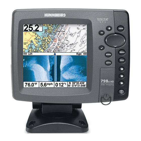
- Page 1 Operations Manual 798ci HD SI Combo 531836-1EN_A...
- Page 2 Your Humminbird® is designed for trouble-free use in even the harshest marine environment. In the unlikely event that your Humminbird® does require repairs, we offer an exclusive Service Policy - free of charge during the first year after purchase, and available at a reasonable rate after the one-year period.
- Page 3 It must be disposed of and collected for recycling and recovery of waste EEE. Humminbird® will mark all EEE products in accordance with the WEEE Directive. It is our goal to comply in the collection, treatment, recovery, and environmentally sound disposal of those products;...
-
Page 4: Table Of Contents
Table of Contents Power On How Sonar Works ® Side Imaging Sonar ....................4 DualBeam PLUS™ Sonar ..................5 Dual Beam Ice Transducer ....6 (optional-purchase XI 9 20 Ice Transducer only) QuadraBeam PLUS™ Sonar ..7 (with optional-purchase QuadraBeam PLUS™ transducer) Universal Sonar 2 .... - Page 5 Table of Contents Snapshot and Recording View................45 Side Beam View ....52 (with optional-purchase QuadraBeam PLUS™ transducer) Bird’s Eye View ...................... 56 Chart View......................57 Combo View ......................59 Chart/Down Combo View..................60 Chart/Side Combo View ..................61 Down/Side Combo View..................62 Down/Sonar Combo View ..................
- Page 6 Table of Contents SD Memory Card Slots Add Maps to Your Fishing System................86 Export Navigation Data.................... 87 Update Software...................... 88 Accessory Bus The Menu System Start-Up Options Menu Normal........................91 Simulator ........................ 92 System Status ......................92 Self Test........................93 Accessory Test......................
- Page 7 Table of Contents SI Colors ......................110 Down Imaging Beam Width .............. 110 (Advanced) Cancel Navigation ............110 (only when Navigating) Sonar X-Press™ Menu (Sonar Views only) Sensitivity ......................112 Upper Range .. 113 (Advanced: Sonar, Split Sonar, Circular Flasher, and Big Digits Views only) Lower Range ......................
- Page 8 Table of Contents Playback Speed (optional-purchase SD Memory Card, ................123 Snapshot and Recording View only) Stop Playback .......... 124 (optional-purchase SD Memory Card only) Navigation X-Press™ Menu (Navigation views only) Waypoint [Name] ........126 (Only with an active cursor on a waypoint) Cursor To Waypoint ............
- Page 9 Table of Contents 83 kHz Sensitivity ........140 (Advanced, DualBeam PLUS™ Sonar only) 455 kHz Sensitivity (Advanced, with optional purchase QuadraBeam PLUS™ transducer) Depth Lines ..................141 (Advanced) SI Range Lines ..........142 (Advanced, Side Imaging® View only) Noise Filter ..................
- Page 10 Table of Contents Clear Map Offset ................157 (Advanced) Shaded Depth ......................157 Chart Detail Level ....................158 Map Borders ......................158 Spot Soundings...................... 159 Contour Lines ........159 (optional-purchase LakeMaster® charts only) Depth Colors .......... 159 (optional-purchase LakeMaster® charts only) Depth Highlight ........
- Page 11 (334) 687-6613. NOTE: Entries in this Table of Contents which list (with Temp/Speed only) require the purchase of separate accessories. You can visit our Web site at humminbird.com to order these accessories online or contact our Customer Resource Center at 1-800-633-1468.
-
Page 13: Power On
Power On Follow the instructions below to power on your Humminbird® control head. Title Screen 1. Press the POWER/LIGHT key. 2. When the Title screen is displayed, press the MENU key to access the Start-Up Options Menu. 3. Use the 4-WAY Cursor Control key to select Normal (if there is a transducer attached to the control head), or Simulator (if there isn’t a... -
Page 14: How Sonar Works
How Sonar Works Sonar technology is based on sound waves. The 700 Series™ Fishing System uses sonar to locate and define structure, bottom contour and composition, as well as depth directly below the transducer. Your 700 Series™ Fishing System sends a sound wave signal and determines distance by measuring the time between the transmission of the sound wave and when the sound wave is reflected off of an object;... - Page 15 When all the echoes are viewed side by side, an easy to interpret “graph“ of the bottom, fish, and structure appears. The sound pulses are transmitted at various frequencies depending on the application. Very high frequencies (455 kHz) are used for greatest definition but the operating depth is limited.
-
Page 16: Side Imaging Sonar
Side Imaging Sonar ® Your 700 Series™ Fishing System uses Side Imaging® sonar to provide a wide yet precise survey of a large area of water, including detailed bottom topography fish- attracting structure orientation. The Side Imaging® transducer returns are processed into an image similar to an aerial photograph. -
Page 17: Dualbeam Plus™ Sonar
DualBeam PLUS™ Sonar Your 700 Series™ Fishing System uses a 200/83 kHz DualBeam PLUS™ sonar system with a wide (60°) area of coverage. DualBeam PLUS™ sonar has a narrowly focused 20° center beam, surrounded by a second beam of 60°, expanding your coverage to an area equal to your depth. -
Page 18: Dual Beam Ice Transducer (Optional-Purchase Xi 9 20 Ice Transducer Only)
Dual Beam Ice Transducer Ice transducer (optional-purchase XI 9 20 Ice Transducer only) Your Fishing System supports the optional- purchase XI 9 20 Ice Transducer which provides selectable dual-frequency sonar with a wide area of coverage. Selectable dual-frequency gives you the option of two beams, and both beams will cover the bottom and provide high definition. -
Page 19: Quadrabeam Plus™ Sonar (With Optional-Purchase Quadrabeam Plus™ Transducer)
QuadraBeam PLUS™ Sonar (with optional-purchase QuadraBeam PLUS™ transducer) Your Fishing System also supports QuadraBeam PLUS™ sonar with the 35° 60° 20° 35° purchase of an additional QuadraBeam 455 kHz 455 kHz 200 kHz PLUS™ transducer. QuadraBeam PLUS™ sonar provides an extremely wide 90° area 83 kHz of coverage. -
Page 20: (Compatible W/ Optional-Purchase Minnkota Trolling Motors)
Universal Sonar 2 (compatible w/ optional-purchase Minnkota trolling motors) Your 700 Series™ Fishing System supports Universal Sonar 2, a state-of-the- art, integrated and protected transducer that is built into the lower unit of Minnkota trolling motors. With Universal Sonar 2, all wiring is concealed inside the indestructible composite shaft—out of sight and out of harm’s way, with... -
Page 21: How Gps Works
MSAS (the MTSAT Satellite Augmentation System) satellites if they are available in your area. The following GPS functionality is currently supported by the 700 Series™ Fishing System when it is connected to the included GPS receiver: • View current position •... -
Page 22: What's On The Sonar Display
What’s on the Sonar Display The 700 Series™ Fishing System can display a variety of useful information about Depth - Water depth can be set to alarm when the water becomes too shallow. Temperature - Water surface temperature. Timer - Elapsed time with Temp/Speed Accessory or GPS Receiver. - Page 23 RTS (Real Time Sonar) Window™ Low Sonar Intensity Return is connected to the 700 Series™ Fishing System. If both devices are connected, then only the What’s on the Sonar Display...
-
Page 24: Understanding The Sonar Display
Understanding the Sonar Display It is important to understand the significance of the display. The display does not show a literal 3- dimensional representation of what is under the water. Each vertical band of data received by the control head and plotted on the display represents something that was detected by a sonar return at a particular time. -
Page 25: Switchfire
SwitchFire™ SwitchFire™ controls how the sonar returns are displayed in the Sonar Views. SwitchFire™ settings are available in the Sonar Menu Tab. To see the maximum sonar information available within the transducer beam so more fish arches and better jig tracking are shown, choose Max Mode. To see less clutter and more fish size accuracy interpreted from the transducer beam, choose Clear Mode. -
Page 26: Bottom Presentation
Bottom Presentation As the boat moves, the unit charts the changes in depth on the display to create a profile of the Bottom Contour. The type of bottom can be determined from the return charted on the display. A Hard Bottom such as compacted sediment or flat rock appears as a thinner line across the display. - Page 27 Structure ID® represents weak returns in blue and strong returns in red. WhiteLine™ highlights the strongest sonar returns in white, resulting in a distinctive outline. This has the benefit of clearly defining the bottom on the display. What’s on the Sonar Display...
-
Page 28: What's On The Side Imaging® Display
What’s on the Side Imaging® Display Side Imaging® displays a number of easily recognizable features that allow for bottom composition determines the intensity of the sonar return. For example, relative density. Upward slopes that face the transducer reflect sonar better than easily recognizable features on the Side Imaging®... - Page 29 Fish also cast shadows. You can use the shadow to interpret how close the fish is to the bottom. is connected to the 700 Series™ Fishfinder. If both devices are connected, then only the What’s on the Side Imaging® Display...
-
Page 30: Understanding The Side Imaging® Display
Understanding the Side Imaging® Display It is important to understand how Side Imaging® technology produces the display. The images you see on the display are produced using sonar technology. The special transducer projects three distinct beams – one beam facing down and two beams pointing out to the side. Down Beam is aimed directly below the boat and provides conical coverage. - Page 31 Side Imaging® sonar echoes are first displayed at the top of the screen, and historical data scrolls down the display as new information is received. The main benefit of Side Imaging® sonar to anglers is that it provides an overall survey of a large area of water.
-
Page 32: Side Imaging® Frequencies And Coverage
Side Imaging® Frequencies and Coverage Side Imaging® sonar uses two very precise sonar beams that are directed to either side of the boat. The beams “illuminate” the bottom contour, structure, and fish, and the results are displayed in a “picture-like” image on the screen. •... -
Page 33: For Best Performance
For Best Performance Use the following tips and examples to help you interpret the Side Imaging® display. For Best Side Imaging® Performance • Boat speed: 2 to 6 mph • Straight line navigation • Minimum turning time and wave turbulence See Side Imaging Tips for more information. -
Page 34: On The Water Interpretation
See Submerged Bridge: A Closer Perspective and the Submerged Bridge: Alternative Perspective illustrations for examples of this. See www.humminbird.com and www.sideimaging.com for a Side Imaging® sonar tutorial and additional information. On the Water Interpretation... - Page 35 Submerged Ravine with Timber Submerged Ravine Submerged Timber Possible Submerged Drop Off Tree Submerged Bridge: A Closer Perspective Submerged Bridge What’s on the Side Imaging® Display...
- Page 36 Submerged Bridge: Alternative Perspective Submerged Bridge - When there is an area directly under the boat that does not have Side Imaging® coverage, a single object may appear as two separate objects on the display. Submerged Standing and Fallen Timber, Plus Bait Fish Bait Fish Standing and Fallen Timber...
- Page 37 Submerged Swimming Pool Swimming Pool Submerged Barge with Dumped Logs Submerged Barge Dumped Logs What’s on the Side Imaging® Display...
-
Page 38: What's On The Down Imaging™ Display
What’s on the Down Imaging™ Display Down Imaging™ uses unique sonar technology to provide information about produce the detailed sonar data that you see on the display. Down Imaging™ and bottom contour, including the following items: Depth - Water depth can be set to alarm when the water becomes too shallow. - Page 39 You can use the shadow to interpret how close the fish is to the bottom. Structure Lower Range device is connected to the 700 Series™ Fishing System. If both devices are connected, then What’s on the Down Imaging™ Display...
-
Page 40: Understanding The Down Imaging™ Display
Understanding the Down Imaging™ Display The images you see on the Down Imaging™ display are produced using sonar technology. Each time the unit pings, a strip of data representing all the echoes received by the transducer are put together on the display to form the image that you see. -
Page 41: Down Imaging™ Sensitivity
Down Imaging™ Sensitivity Use Down Sensitivity to control how the sonar returns appear on the display. Increase the sensitivity to reveal weaker returns that may be of interest, especially in very clear water or greater depths. Decrease the sensitivity to eliminate the clutter from the display that is sometimes present in murky or muddy water. -
Page 42: Views
Views The sonar and navigation information from your Fishing System is displayed on your screen in a variety of easy-to-read views. There are many views available on your Fishing System. • Default View: When you first power up the 798ci HD SI control head, Side Imaging®/Sonar Combo View will be the default view. - Page 43 To program each PRESET key: Another way to access your favorite views quickly is to store them on the VIEW PRESET keys. Instead of using the VIEW key to cycle through every view to find the one you want, you can program the VIEW PRESET keys to display a specific view immediately.
-
Page 44: Side Imaging® View
Side Imaging® View Side Imaging® View shows a shadowed right- and left-looking view from the boat as the boat passes over the bottom. See What’s on the Side Imaging® Display and Understanding the Side Imaging® Display for more information about interpreting the Side Imaging® View. Side Imaging®... - Page 45 - The depth of the sonar return will be displayed in the cursor information box. - Zoom+: Press the ZOOM+ key, and a zoom box will appear and magnify the area you choose, providing more detail in the individual sonar returns. The zoom scale will increase or decrease as you press + or - repeatedly.
-
Page 46: Down Imaging™ View
Down Imaging™ View Down Imaging™ View uses the razor-thin, high-definition profiling beams to produce the detailed sonar data that you see on the display. Sonar returns are charted on the right side of the display. As new information is received, the historical information scrolls left across the display. - Page 47 Down Imaging™ View Upper Depth Depth Range Temperature Surface Clutter White Streaks (possibly vegetation or fish) Bottom Return Speed Lower Depth Range NOTE: See What’s on the Down Imaging™ Display and Down Imaging™ X-Press™ Menu for more information. Views...
-
Page 48: Sonar View
Sonar View Sonar View presents a historical log of sonar returns. The most recent sonar returns are charted on the right side of the window. As new information is received, the historical information scrolls left across the display. • Upper and Lower Depth Range numbers indicate the distance from the surface of the water to a depth range sufficient to show the bottom. -
Page 49: Sonar Zoom View
Sonar Zoom View Sonar Zoom View provides a magnified view of the bottom and structure. The Sonar Zoom View makes it easier to see separate sonar returns that would usually be displayed close together, such as those caused by fish suspended close to the bottom or within structure. -
Page 50: Split Sonar View
Split Sonar View Split Sonar View displays sonar returns from each down beam frequency on separate sides of the screen. You can use the Split Sonar View to make side by side comparisons between the sonar returns from both beams. •... -
Page 51: Big Digits View
Big Digits View Big Digits View provides digital data in a large, easy-to-see format. • Digital Readouts: Depth is always displayed. Readouts for temperature, speed, and Triplog information are displayed automatically if the appropriate accessory is connected to the Fishing System. NOTE: The digital readouts in the Big Digits View cannot be customized. -
Page 52: Circular Flasher View
Circular Flasher View Circular Flasher View provides two ways to view sonar data in traditional flasher format. The view is controlled by the Ice Fishing Mode menu option in the Sonar Menu Tab. • When Ice Fishing Mode is off, the Circular Flasher View displays Real Time Sonar (RTS™) data in a traditional flasher format. - Page 53 Ice Fishing Mode: Off When Ice Fishing Mode is off, the Circular Flasher View displays Real Time Sonar (RTS™) data in a traditional flasher format. • Flasher X-Press™ Menu: Press the MENU key once in the Circular Flasher View. Use the X-Press™ Menu to set the Sensitivity, Upper Range, and Lower Range.
- Page 54 Ice Fishing Mode: On When Ice Fishing Mode is on, the Circular Flasher View displays the sonar data in traditional flasher format with additional features including Zoom and Depth Cursor. • Sensitivity: When you turn on Ice Fishing Mode, the fishfinder’s sensitivity settings are adjusted automatically to accommodate ice fishing conditions.
- Page 55 To activate the Depth Cursor: Use the Depth Cursor to identify depth on the flasher display. 1. Set up: Press the VIEW key repeatedly until the Circular Flasher View is displayed on the screen. Turn on the Ice Fishing Mode (see Sonar Menu Tab).
- Page 56 To activate Flasher Zoom: The Zoom feature displays a 2x magnified view of the area you choose on the flasher display. 1. Set up: Press the VIEW key repeatedly until the Circular Flasher View is displayed on the screen. Turn on the Ice Fishing Mode (see Sonar Menu Tab).
-
Page 57: Snapshot And Recording View
Snapshot and Recording View The Snapshot and Recording View displays the screen snapshots and recordings that are saved on the optional-purchase SD memory card installed in the control head. Use this view to review the snapshot and recording file details, start recording, and adjust the recording settings. •... - Page 58 Screen Snapshots Screen Snapshots are saved pictures of the view on the screen. The screen snapshot will include the menus, dialog boxes, warnings, and messages that were active when the screen snapshot was taken. Saved Screen Snapshots can be viewed from the Snapshot and Recording View or Chart View. The Screen Snapshot feature is available when an optional-purchase SD memory card is installed and Screen Snapshot is On (see Accessory Menu Tab: Screen Snapshot).
- Page 59 • Use an optional-purchase SD memory card reader connected to a PC to view the saved screen snapshot data files on your optional-purchase SD memory card (see humminbird.com for details). You will notice that a .DAT (or a .TXT) file is created for every .PNG screen snapshot. This data file is required for viewing the screen snapshots from your control head, so don’t delete these files.
- Page 60 Recording and Playback The Recording feature records active sonar information. When the recording is played back, the views that were active during the recording are available in Playback. The Recording and Playback feature is available when an optional- purchase SD memory card is installed and Screen Snapshot is On (see Accessory Menu Tab: Screen Snapshot).
- Page 61 Notes about Recording: • While recording, press the EXIT key to exit the Snapshot and Recording X-Press™ Menu and scroll to a different view. Recording will continue. • The slider bar at the bottom of the Snapshot and Recording View shows the recording progress and remaining space on the SD memory card.
- Page 62 Delete a Recording: Delete a Recording 1. From Snapshot Recording View, press the UP or DOWN Cursor keys to scroll through the saved files and highlight a saved Recording. From Snapshot and Recording 2. Press the Menu key once, and View, select Delete select Delete Recording from the...
- Page 63 Recording Playback Name of recording Time and Date recording started Position where recording started Current Ping Rate Average Ping Rate Amount of time remaining to play Playback speed icons Amount of Time Amount of time remaining to play Already Played Overall length of recording Views...
-
Page 64: Side Beam View (With Optional-Purchase Quadrabeam Plus™ Transducer)
Side Beam View (with optional-purchase QuadraBeam PLUS™ transducer) Side Beam View displays sonar data from the left and right 455 kHz beams and the 200 kHz down-looking beam in one view. Side Beam View is only available if you have connected an optional-purchase QuadraBeam PLUS™ transducer accessory and set Transducer Select to QuadraBeam (see Sonar Menu Tab: Transducer Select). - Page 65 Default Layout • Top: The top portion of the display presents a historical log of sonar returns from the 200 kHz down-looking sonar beam. New information in the down beam panel scrolls from right to left. • Bottom: The bottom portion of the display presents a historical log of sonar returns from the 455 kHz right- and left-looking sonar beams.
- Page 66 Classic Layout • Top: The top portion of the display presents a historical log of sonar returns from the 200 kHz down-looking sonar beam. New information in the down beam panel scrolls from right to left. • Bottom: The bottom portion of the display presents a historical log of sonar returns from the 455 kHz right- and left-looking sonar beams.
- Page 67 Slanted Layout This layout is presented as three slanted panels representing the two 455 kHz side sonar beams and the 200 kHz down-looking sonar beam. New information appears on the right and scrolls to the left. Side Beam View, Slanted Layout Depth Speed Left Side 455 kHz...
-
Page 68: Bird's Eye View
Bird’s Eye View Bird's Eye View shows a 3D perspective view of the track and the chart’s land contour from a point above and behind the boat (the eye point). As the boat turns, the eye point moves to follow the boat. •... -
Page 69: Chart View
Chart View Chart View shows cartography from the built-in UniMap™ or an optional SD card map for the area surrounding your current position. The current track (also known as the position history or breadcrumb trail) showing where the boat has been, along with saved tracks, waypoints, and the current route (when navigating), are overlaid on the chart. - Page 70 Chart View with Active Cursor, shown with Optional-Purchase Navionics® Cartography Depth Cartography Active Cursor Map Scale Bearing of Boat with Respect to True North Distance to the Cursor and Latitude and Bearing Longitude to Cursor Position of Cursor Views...
-
Page 71: Combo View
Combo View Combo View is displayed as a split screen, where the Chart window is displayed on the left, and the Sonar window is displayed on the right side of the screen. • X-Press™ Menu: Press the MENU key once to access the X-Press™ Menu for this combo view. -
Page 72: Chart/Down Combo View
Chart/Down Combo View Chart/Down Combo View shows chart information and Down Imaging™ information in a combination split screen. The Chart window is displayed on the left, and the Down Imaging™ window is displayed on the right side of the screen. •... -
Page 73: Chart/Side Combo View
Chart/Side Combo View Chart/Side Combo View shows chart information and Side Imaging® sonar information in a combination split screen. The Chart information is displayed in the top window, and Side Imaging® information is displayed in the bottom window. • X-Press™ Menu: Press the MENU key once to access the X-Press™ Menu for this combo view. -
Page 74: Down/Side Combo View
Down/Side Combo View Down/Side Combo View shows Down Imaging™ and Side Imaging® sonar information in a combination split screen. The Down Imaging™ information is displayed in the top window, and the Side Imaging® information is displayed in the bottom window. •... -
Page 75: Down/Sonar Combo View
Down/Sonar Combo View Down/Sonar Combo View shows Down Imaging™ and traditional Sonar information in a combination split screen. The Sonar information is displayed in the top window, and Down Imaging™ information is displayed in the bottom window. • X-Press™ Menu: Press the MENU key once to access the Down Imaging™... -
Page 76: Sonar/Side Combo View
Sonar/Side Combo View Sonar/Side Combo View shows traditional Sonar information and Side Imaging® sonar information in a combination split screen. The Sonar information is displayed in the top window, and the Side Imaging® information is displayed in the bottom window. •... -
Page 77: Down/Side/Sonar Combo View
Down/Side/Sonar Combo View Down/Side/Sonar Combo View shows Down Imaging™ and traditional Sonar information at the top of the screen. Side Imaging® is displayed in the bottom window of the screen. • X-Press™ Menu: Press the MENU key once to open the X-Press™ Menu. -
Page 78: View Orientation
View Orientation Both Chart and Combo Views allow you to choose the orientation of the view (see Navigation Menu Tab: Chart Orientation). In both orientations, the view pans automatically so that the boat is always centered on the display. • North-Up: True North is shown at the top of the display. Objects located to the north of the boat are drawn above the boat. - Page 79 Zooming: Press the Plus (+) key to Zoom In and the Minus (-) key to Zoom Out to see the cartography at different magnification levels. The zoom level is indicated on the left side of the display. If you zoom in beyond the available chart data, the display will go into Overzoom mode whereby the last available chart data is amplified to reflect the level selected.
- Page 80 Nearest Tide Station: Tide information for the nearest tide station to your present position will be displayed. This includes the position of the station and the times of the high and low tides for today’s date. A tide graph is also displayed showing the rise and fall of the tides for the 24 hour time period encompassing the date.
-
Page 81: Introduction To Navigation
The Current Track shows the position history since the unit was powered up (maximum of 20,000 trackpoints displayed). You can clear the Current Track or save it at any time. Your 700 Series™ Fishing System can store up to 50 saved tracks, each containing 20,000 trackpoints. The current track represents your actual path so far. - Page 82 Waypoints, Routes, and Tracks Depth Route Decluttered BRG: Bearing to Waypoints Waypoint Track XTE: Cross Track Error. Distance Waypoint of Boat from Route DTG: Distance to Go to Waypoint Bearing of Boat Water with Respect to Surface True North Temperature Speed of Boat NOTE: When two or more waypoints overlap, or are displayed close together on a chart view, the screen will automatically declutter—waypoint names will shorten...
-
Page 83: Save, Edit, Or Delete A Waypoint
Save, Edit, or Delete a Waypoint Save your current position as a waypoint: On any view, press the MARK key to save the current position of the boat as a waypoint. Save the cursor position as a waypoint: On the Chart or Chart Combo Views, use the 4-WAY Cursor Control key to move the cursor to the position you want to save as a waypoint. - Page 84 Program a specific position as a waypoint: To create a waypoint that is NOT your current position, from the Waypoints submenu select Create, and press the RIGHT Cursor key. Use the 4-WAY Cursor Control key to program a waypoint name, latitude, longitude, and icon before selecting Save. Edit a waypoint: From the Waypoints submenu, select Edit and press the RIGHT Cursor key to display the saved waypoints list.
-
Page 85: Navigate To A Waypoint Or Position
Navigate to a Waypoint or Position Navigate to the cursor position: From the Chart, Side Imaging®, Down Imaging™, or Combo View, use the 4-WAY Cursor Control key to move the cursor to a position or waypoint on the display. Press the GOTO key. Navigation will begin immediately. -
Page 86: Add A Waypoint Target Or Trolling Grid
Add a Waypoint Target or Trolling Grid The Waypoint Target shows a target consisting of concentric circles in various distance ranges centered on the waypoint you choose. The Trolling Grid shows various distance ranges in grid format from the waypoint you choose. The trolling grid can be used as a guide when trolling around a waypoint. -
Page 87: Save, Edit, Or Delete A Route
Save, Edit, or Delete a Route Save the current route: While you are navigating, the current route can be saved. From the Navigation X-Press™ Menu, select Save Current Route, and press the RIGHT Cursor key. Navigation will continue. Display the Routes submenu: From any view, press the MENU key twice to display the Main Menu, then press the RIGHT Cursor key to select the Navigation tab. -
Page 88: Save Or Clear A Current Track
Route Info: From the Routes submenu, select Info, and press the RIGHT Cursor key. The saved routes list will appear. Select a route, and press the RIGHT Cursor key. The following information will be displayed for the route you select: The waypoints in the route, with the distance and bearing from each waypoint to the next, as well as the distance and bearing from the current position to the first waypoint in the route. -
Page 89: Man Overboard (Mob) Navigation
Delete a saved track: From the Saved Tracks submenu, select Delete, and press the RIGHT Cursor key to display the saved tracks list. Select the track you want to delete and press the RIGHT Cursor key. You will be asked to confirm deletion before the track is permanently deleted. - Page 90 MOB Navigation Target surrounding Position where MOB waypoint man fell overboard Elapsed time since MOB was activated MOB waypoint Boat’s current position Map Scale BRG - Bearing to waypoint XTE: Cross Track DTG - Distance Error. Distance to waypoint of Boat from Route Latitude and Longitude Position of Cursor...
-
Page 91: What's On The Control Head
What’s on the Control Head Your 700 Series™ interface is easy to use. A combination of keys and special features allows you to control what you see on the display. Refer to the following illustration, and see Key Functions for more information. -
Page 92: Key Functions
Key Functions Your Fishing System user interface consists of a set of easy-to-use keys that work with various on-screen views and menus to give you flexibility and control over your fishing experience. POWER/LIGHT Key The POWER/LIGHT key is used to power the Fishing System on and off. -
Page 93: Zoom (+/-) Key
ZOOM (+/-) Key The Zoom (+/-) key has multiple functions, depending on the situation: • In any of the Navigation Views or the Sonar Zoom View, press the +/-Zoom key to change the scale of the view to appear closer or farther away. -
Page 94: Info Key
• Chart Views: Press any arrow on the 4-WAY Cursor Control key to pan the chart and highlight decluttered waypoint icons. NOTE: In either Freeze Frame or Active Cursor mode, you can also make the cursor move diagonally by pressing in between two of the arrows on the 4-WAY Cursor Control key. -
Page 95: Menu Key
MENU Key The MENU key is used to access the menu system. See The Menu System for more information. • Start-Up Options Menu: Press the MENU key during the power up sequence to view the Start-Up Options menu. • X-Press™ Menu: Press the MENU key once in any view to access the X-Press™... -
Page 96: Goto Key
GOTO Key The GOTO key has multiple functions, depending on the situation: • If the Cursor is active, press the GOTO key while in any view to create a waypoint and start navigation towards that waypoint. • If the Cursor is not active, press the GOTO key to display the saved waypoints list, and then highlight a waypoint. -
Page 97: Sd Memory Card Slots
Inserting an MMC/SD into the Card Slot NOTE: The SD Memory Cards require a separate purchase. For more information, visit our Web site at humminbird.com or contact our Customer Resource Center at 1-800-633-1468. To insert an MMC/SD card: 1. Remove the MMC/SD slot cover. -
Page 98: Add Maps To Your Fishing System
You can also purchase SD memory cards with additional chart information for a particular location. NOTE: The SD memory cards require a separate purchase. Your 700 Series™ Fishing System supports LakeMaster®, Navionics® Gold, HotMaps™ and HotMaps™ Premium on SD card media. Your 700 Series™ Fishing System does NOT support Navionics®... -
Page 99: Export Navigation Data
The USB Memory Card Reader accessory can be used in conjunction with your personal computer to view and organize your exported navigation data. To purchase this accessory, visit our Web site at humminbird.com or contact our Customer Resource Center at 1-800-633-1468. -
Page 100: Update Software
Update Software Set up an online account at humminbird.com so that you will receive the latest Humminbird® news and software upgrades for your Fishing System. You can also download HumminbirdPC™ from your account, which allows you to manage your waypoints, routes, and tracks on your personal computer. -
Page 101: Accessory Bus
Manual for additional details. NOTE: Accessories to enable WeatherSense® and the SmartCast® Wireless Sonar Link require separate purchases. You can visit our Web site at humminbird.com or contact our Customer Resource Center at 1-800-633-1468 for additional details. NOTE: See your installation guide for details. -
Page 102: The Menu System
The Menu System The Menu System is divided into easy-to-use menu modules. The main components of the menu system are as follows: • Start-Up Options Menu: Press the MENU key during the power on sequence to view the Start-Up Options Menu. From the Start-Up Options Menu, you can choose the following Fishing System Modes: Normal, Simulator, System Status, and PC Connect. -
Page 103: Start-Up Options Menu
Start-Up Options Menu Press the MENU key during the power on sequence to view the Start-Up Options Menu, and select one of the modes described on the following pages. Also, see Power On for additional information. Normal Use Normal for on-the-water operation with a transducer connected. If a functioning transducer is connected, Normal operation will be selected automatically at power up, and your Fishing System can be used on the water. -
Page 104: Simulator
Simulator Use Simulator to learn how to use your Fishing System before taking your boat on the water. The Simulator is a very powerful tool that provides a randomly-updated display which simulates on the water operation. Simulator We recommend going through this manual while using the Simulator, since all of the menus function and affect the display in the same way as... -
Page 105: Self Test
Self Test Screen Self Test displays results from the internal diagnostic self test, including unit serial number, Printed Circuit Board (PCB) serial number, software revision, total hours of operation, and the input voltage. Accessory Test Accessory Test lists the accessories connected to the system. -
Page 106: Gps Diagnostic View
GPS Diagnostic View shows a sky chart and numerical data from the GPS receiver. The sky chart shows the location of each visible GPS satellite with its satellite number and a signal strength bar. A dark gray bar indicates that the satellite is being used to determine your current position. -
Page 107: Pc Connect And Software Updates (With Optional-Purchase Pc Connect Cable Only)
NOTE: See also SD Memory Card Slots: Update Software. NOTE: The PC Connect cable requires a separate purchase. For more information, visit our Web site at humminbird.com or contact our Customer Resource Center at 1-800-633-1468. Updating Software requires the following top-level steps: 1. -
Page 108: X-Press™ Menu
X-Press™ Menu The X-Press™ Menu provides a shortcut to your most frequently-used settings. The options provided on the X-Press™ Menu correspond with the current view. For example, if you are in a Sonar View and press the MENU key once, the Sonar X-Press™... -
Page 109: Main Menu
Main Menu The Main Menu provides the standard set of menu options, including the settings that are changed less frequently. The Main Menu is organized under the following tabs to help you find a specific menu item quickly: Alarms, Sonar, Navigation, Chart, Setup, Views, and Accessories. -
Page 110: Quick Tips For The Main Menu
Quick Tips for the Main Menu • From any menu option on a menu tab, press the EXIT key to jump directly to the top of the tab. • From the bottom of a menu tab, press the DOWN key to jump directly to the top of the tab. -
Page 111: Note For All Menu Settings
Note for all Menu Settings The settings in all menus are adjusted in the same way. Simply use the 4-WAY Cursor Control key to highlight a menu option, and then change the settings or activate the option (see Main Menu or X-Press™ Menu). Below is an example of how the menu options are described in this manual. -
Page 112: User Mode (Normal Or Advanced)
Menu options can be simplified or expanded by setting your Fishing System User Mode to Normal or Advanced. Normal Mode is the default setting when you first power on your 700 Series™ Fishing System. Normal mode is provided for users who want greater simplicity and fewer menu choices. - Page 113 Sonar Tab, Normal Mode Sonar Tab, Advanced Mode Main Menu...
-
Page 114: Side Imaging® X-Press™ Menu (Side Imaging® Views Only)
Side Imaging® X-Press™ Menu (Side Imaging® Views only) The Side Imaging® X-Press™ Menu provides a shortcut to your most frequently-used settings. Press the MENU key once while in any of the Side Imaging® Views to access the Side Imaging® X-Press™ Menu. NOTE: Menu options can be expanded or simplified by setting the User Mode to Advanced or Normal. -
Page 115: Si Side
SI Side Settings: Left, Both, Right; Default = Both SI Side sets which transducer beam from the Side Imaging® beams will be shown on the display. SI Sensitivity Settings: Auto, 1 to 20, where Low = 1, High = 20; Default = 10 SI Sensitivity controls how the sonar returns are displayed on the Side Imaging®... -
Page 116: Si Enhance
SI Enhance Settings: Press the RIGHT Cursor key. SI Enhance allows you to adjust your Side Imaging® View in three categories: Sensitivity, Contrast, and Sharpness. Whether you’re searching the Side Imaging® data for fish or certain bottom contour, the most effective settings will vary with the situation. The display will update as you adjust each category. -
Page 117: Si Range
When Contour Mode is turned on, the bottom is graphed at a constant point on the display, regardless of changes in depth. The Side Imaging® beams are divided by a vertical line. The water column is removed from the view, which allows the display to show targets at their linear horizontal distance. -
Page 118: Si Colors
SI Colors Settings: Blue, Amber 1, Amber 2, Brown, Green, Inverse, Gray, Green/Red, Default = Blue SI Colors allows you to select which color palette you would like to use for the Side Imaging® display. Cancel Navigation (only when Navigating) Settings: Press the RIGHT Cursor key and follow screen instructions. -
Page 119: Down Imaging™ X-Press™ Menu (Down Imaging™ Views Only)
Down Imaging™ X-Press™ Menu (Down Imaging™ Views only) The Down Imaging™ X-Press™ Menu provides a shortcut to your most frequently-used settings. Press the MENU key once while in any of the Down Imaging™ Views to access the Down Imaging™ X-Press™ Menu. NOTE: Menu options can be expanded or simplified by setting the User Mode to Advanced or Normal. -
Page 120: Down Sensitivity
Down Sensitivity Settings: Auto, 1 to 20, where Low = 1, High = 20; Default = 10 Down Sensitivity controls how the sonar returns are displayed on the Down Imaging™ Views. Increase the Down Sensitivity to reveal weaker returns that may be of interest, especially in very clear water or greater depths. -
Page 121: Lower Range
Lower Range Settings: Auto, 10 to 1500 ft, 3 to 500 m [International Models only]; Default = Auto Lower Range sets the deepest depth range that will be displayed by the unit. Auto: The Lower Range will be adjusted by the unit to follow the bottom automatically. -
Page 122: Si Colors
SI Colors Settings: Blue, Amber 1, Amber 2, Brown, Green, Inverse, Gray, Green/Red, Default = Blue SI Colors allows you to select which color palette you would like to use for the Side Imaging® display. Down Imaging Beam Width (Advanced) Settings: Narrow, Medium, Wide;... -
Page 123: Sonar X-Press™ Menu (Sonar Views Only)
Sonar X-Press™ Menu (Sonar Views only) The Sonar X-Press™ Menu provides a shortcut to your most frequently-used settings. Press the MENU key once while in any of the Sonar Views to access the Sonar X-Press™ Menu. NOTE: Menu options can be expanded or simplified by setting the Fishing System User Mode to Advanced or Normal. -
Page 124: Sensitivity
Sensitivity Settings: Low = 1, High = 20; Default = 10 Sensitivity controls how much detail is shown on the display and will adjust the sensitivity of all sonar frequencies. When operating in very clear water or greater depths, increase the sensitivity to see weaker returns that may be of interest. -
Page 125: Upper Range (Advanced: Sonar, Split Sonar, Circular Flasher, And Big Digits Views Only)
Upper Range (Advanced: Sonar, Split Sonar, Circular Flasher, and Big Digits Views only) Settings: 0 to 1490 ft or 0 to 497 m [International Models only]; Default = 0 Upper Range sets the shallowest depth range that will be displayed on the Sonar, Split Sonar, Circular Flasher, and Big Digits Views. -
Page 126: Chart Speed
Chart Speed Settings: 1-9, Ultra, where 1 = Slow, 9 = Fast, Ultra = Fastest; Default = 5 Chart Speed determines the speed at which the sonar information moves across the display, and consequently the amount of detail shown. A faster speed shows more information and is preferred by most anglers; however, the sonar information moves across the display quickly. -
Page 127: Bottom Lock (Sonar Zoom View Only)
Bottom Lock (Sonar Zoom View only) Settings: Off, On; Default = Off Bottom Lock changes the mode of the zoomed view in the Sonar Zoom View. Bottom Lock continuously graphs the bottom at a constant point on the display regardless of changes in depth. This “flattens“ out the bottom contour, but is effective at showing fish on or near the bottom. -
Page 128: Flasher X-Press™ Menu (Circular Flasher View Only)
Flasher X-Press™ Menu (Circular Flasher View only) The Flasher X-Press™ Menu provides a shortcut to your most frequently-used settings. Press the MENU key once while in the Circular Flasher View to access the Flasher X-Press™ Menu. NOTE: Menu options will vary depending on system settings, such as whether you are currently navigating. -
Page 129: Sensitivity
Sensitivity Settings: Low = 1, High = 20; Default = 10 Sensitivity controls how much detail is shown on the display and will adjust the sensitivity of all sonar frequencies. When operating in very clear water or greater depths, increase the sensitivity to see weaker returns that may be of interest. -
Page 130: Lower Range
Lower Range Settings: Auto, 10 to 1500 ft, 3 to 500 m [International Models only]; Default = Auto Lower Range sets the deepest depth range that will be displayed by the unit. Auto is the default setting. Auto: The Lower Range will be adjusted by the unit to follow the bottom automatically. -
Page 131: Color Palette (Circular Flasher View, Ice Fishing Mode Only)
Color Palette (Circular Flasher View, Ice Fishing Mode only) Settings: Palette 1, Palette 2, Palette 3; Default = Palette 3 Color Palette sets the colors used to display sonar returns in the Circular Flasher View when Ice Fishing Mode is turned on. The active color palette is shown in the center of the circular flasher display. -
Page 132: Snapshot And Recording X-Press™ Menu (Snapshot And Recording View Only)
Snapshot and Recording X-Press™ Menu (Snapshot and Recording View only) The Snapshot and Recording X-Press™ Menu provides access to the snapshot management and sonar recording functions. Press the MENU key once while in the Snapshot and Recording View to access the Snapshot and Recording X-Press™... -
Page 133: Start Recording (Optional-Purchase Sd Memory Card, Snapshot And Recording View Only)
Start Recording (optional-purchase SD Memory Card, Snapshot and Recording View only) Settings: Press the RIGHT Cursor key to activate. Start Recording allows you to start sonar recording from the Snapshot and Recording View. This menu option is only available when an optional-purchase SD memory card is installed and Snapshot and Recording View is on the screen. -
Page 134: Delete Recording (Optional-Purchase Sd Memory Card, Snapshot And Recording View Only)
Delete Recording (optional-purchase SD Memory Card, Snapshot and Recording View only) Settings: Press the RIGHT Cursor key and follow screen instructions. Delete Recording allows you to delete a single sonar recording. This menu option is only available when an optional-purchase SD memory card is installed, Snapshot and Recording View is on the screen, and you have selected a recording file. -
Page 135: Playback Speed (Optional-Purchase Sd Memory Card, Snapshot And Recording View Only)
Playback Speed (optional-purchase SD Memory Card, Snapshot and Recording View only) Settings: Record, Rewind 1, Rewind 2, Slow Play Reverse, Pause, Slow Play, Normal Play, Fast Forward 1, Fast Forward 2, Stop Playback Speed allows you to specify the playback speed for a sonar recording from the Snapshot and Recording View. -
Page 136: Stop Playback (Optional-Purchase Sd Memory Card Only)
Stop Playback (optional-purchase SD Memory Card only) Settings: Press the RIGHT Cursor key to activate. Stop Playback allows you to stop playback of a sonar recording from any view. This menu option is only available when an optional-purchase SD memory card is installed and Recording Playback is active. -
Page 137: Navigation X-Press™ Menu (Navigation Views Only)
Navigation X-Press™ Menu (Navigation Views only) The Navigation X-Press™ Menu provides a shortcut to your most frequently-used settings. Press the MENU key once while in the Bird's Eye, Chart, or Combo View to access the Navigation X-Press™ Menu. NOTE: Menu options will vary depending on system settings, such as whether you are currently navigating. -
Page 138: Waypoint [Name] (Only With An Active Cursor On A Waypoint)
Waypoint [Name] (Only with an active cursor on a waypoint) Settings: Edit, Delete, Target, Grid Waypoint [Name] allows you to view the Waypoints submenu for the waypoint under your cursor. You can move the cursor onto an existing waypoint and press the MENU key once, or use Cursor to Waypoint to select a waypoint from the saved waypoints list. -
Page 139: Save Current Track
Save Current Track Settings: Press the RIGHT Cursor key and follow screen instructions. Save Current Track allows you to save the current track on the display. After the current track is saved, a new current track is started. Save Current Track appears on the Navigation X-Press™... -
Page 140: Cancel Navigation (Only When Navigating)
Cancel Navigation (only when Navigating) Settings: Press the RIGHT Cursor key and follow screen instructions. Cancel Navigation discards the current route and exits Navigation Mode. This menu option will only appear when you are currently navigating a route. This will not delete a previously-saved route. Cancel MOB Navigation (only when MOB Navigation is activated) Settings: Press the RIGHT Cursor key and follow screen... -
Page 141: Sonar Window (Combo View Only)
Sonar Window (Combo View only) Settings: Wide, Medium, Narrow; Default = Medium Sonar Window sets the size of the Sonar Window in the Combo View. Sonar Window can only be accessed from the Combo View. Waypoint [Name] (Most recently-created waypoint) Settings: Edit, Delete, Go To, Target, Grid Waypoint [Name] allows you to view the waypoints submenu for the most recently created waypoint. -
Page 142: Alarms Menu Tab
Alarms Menu Tab From any view, press the MENU key twice to access the Main Menu. The Alarms tab will be the default selection. NOTE: When an alarm is triggered, you can silence it by pressing any key. The alarm will be silenced, and will not be triggered again until a new instance of the alarm condition is detected. -
Page 143: Depth Alarm
Depth Alarm Settings: Off, 1 to 100 ft, or 0.5 to 30 m [International Models only]; Default = Off Depth Alarm sounds when the depth becomes equal to or less than the menu setting. Fish ID Alarm Settings: Off, All, Large/Medium, Large; Default = Off Fish ID Alarm sounds when the Fishing System detects fish that correspond to the alarm setting. -
Page 144: Temp. Alarm
Temp. Alarm Settings: Off, 33-120 Fahrenheit, 0-50 Celsius [International Models only]; Default = Off Temp. Alarm sounds when the water temperature detected by the Fishing System reaches the Temp. Alarm setting, which is either set in degrees Fahrenheit or Celsius [International Models only]. For example, if the Temp. -
Page 145: Arrival Alarm
Arrival Alarm Settings: Off, 25 to 3000 ft, 10 to 1000 m [International Models only]; Default = 150 ft, 50 m Arrival Alarm sounds when the boat has either exceeded the distance to the destination waypoint, or has entered the Arrival Alarm Circle, based on the menu setting when navigating. -
Page 146: Sonar Menu Tab
Sonar Menu Tab Press the MENU key twice to access the Main Menu and then press the RIGHT Cursor key until the Sonar tab is selected. NOTE: Menu options can be expanded or simplified by setting the User Mode to Advanced or Normal. See Main Menu: User Mode for details. -
Page 147: Beam Select
Beam Select Settings: 200/83 kHz, 200 kHz, 83 kHz, Default = 200 kHz Beam Select sets which sonar returns from the transducer will be displayed on the screen. When set to 200/83 kHz, the returns from both beams are blended by starting with the 83 kHz wide beam return, dimming it, and then overlaying it with the 200 kHz narrow beam return. -
Page 148: Surface Clutter
Surface Clutter Settings: Low = 1 to High = 10; Default = 5 Surface Clutter adjusts the filter that removes surface clutter noise caused by algae and aeration. The lower the setting, the less surface clutter will be displayed. Surface Clutter Surface Clutter SwitchFire™... -
Page 149: Fish Id
Fish ID+™ Settings: Off, On; Default = On Fish ID+™ uses advanced signal processing to interpret sonar returns and will display a Fish Symbol when very selective requirements are met. When a fish is detected, a fish icon and its depth are displayed above the return that has been classified as being a fish. -
Page 150: Fish Id Sensitivity
Fish ID Sensitivity Settings: Low = 1, High = 10; Default = 5 Fish ID Sensitivity adjusts the threshold of the Fish ID+™ detection algorithms. Selecting a higher setting allows weaker returns to be displayed as fish. This is useful for identifying smaller fish species or baitfish. Selecting a lower setting displays fewer fish from weak sonar returns. -
Page 151: Sonar Colors (Sonar View, Sonar Zoom View, Circular Flasher View, And Big Digits View)
Sonar Colors (Sonar View, Sonar Zoom View, Circular Flasher View, and Big Digits View) Settings: Gray, Green, Inverse, Original Palette, Palette 1, Palette 2, Palette 3; Default = Original Palette Sonar Colors allows you to select which color palette you would like to use for the display. -
Page 152: Zoom Width
(see Setup Menu Tab: User Mode), and Transducer Select is set to QuadraBeam (see Sonar Menu Tab: Transducer Select). NOTE: Visit our Web site at humminbird.com to order this accessory online or contact our Customer Resource Center at 1-800-633-1468. Sonar Menu Tab... -
Page 153: Depth Lines (Advanced)
Depth Lines (Advanced) Settings: Off, On; Default = On Depth Lines divide the display into four equal sections that are separated by three horizontal depth lines. The depth of each line is displayed along the depth scale. You can turn Depth Lines On or Off. Depth Lines Depth Lines Sonar Menu Tab... -
Page 154: Si Range Lines (Advanced, Side Imaging® View Only)
SI Range Lines (Advanced, Side Imaging® View only) Settings: Off, On; Default = Off SI Range Lines divide each side beam range into four equal sections on the display. SI Range Lines can be used to interpret the location of objects on the display. -
Page 155: Noise Filter (Advanced)
SI Range Lines (with Contour Mode On) Range Numbers SI Range Lines Noise Filter (Advanced) Settings: Off, Low, Medium, High 1, High 2, High 3; Default = Low Noise Filter adjusts the sonar Noise Filter to limit interference on the display from sources such as your boat engine, turbulence, or other sonar devices. -
Page 156: Max Depth (Advanced)
Max Depth (Advanced) Settings: Auto, 10 to 1500 ft, 3 to 500 m [International Models only]; Default = Auto Max Depth controls the maximum depth of operation. When Max Depth is set to Auto, the Fishing System will acquire bottom readings as needed (within the capacity of the unit). -
Page 157: Transducer Select
Side Imagsing® and DualBeam PLUS™ technology. Your Fishing System also supports the optional-purchase QuadraBeam PLUS™ transducer and optional-purchase Universal Sonar 2. NOTE: To purchase transducers, visit our Web site at humminbird.com or call our Customer Resource Center at 1-800-633-1468. Down Imaging Beam Width (Advanced, Down Imaging™... -
Page 158: Navigation Menu Tab
Navigation Menu Tab Press the MENU key twice to access the Main Menu, then press the RIGHT Cursor key to select the Navigation tab. NOTE: Menu options will vary depending on system settings, such as whether you are currently navigating. NOTE: Menu options can be expanded or simplified by setting the User Mode to Advanced or Normal. -
Page 159: Current Track
Current Track Settings: Save, Clear, Appearance Current Track allows you to view the Current Track submenu. See Introduction to Navigation: Save or Clear a Current track for more information. The Current Track Submenu contains the following menu options: Save allows you to save the current track. Clear allows you to delete the current track. -
Page 160: Saved Tracks
Saved Tracks Settings: Edit, Delete, Default Saved Tracks allows you to view the Saved Tracks submenu. See Introduction to Navigation: Edit, Delete, or Hide Saved Tracks for more information. The Saved Tracks Submenu contains the following menu options: Edit allows you to select a saved track and change its Name, Visibility (hidden or visible), Style, and Color (for track line styles only). -
Page 161: Waypoints
Waypoints Settings: Create, Edit, Delete, Cursor To, Go To, Target, Grid Waypoints allows you to view the Waypoints submenu. See Introduction to Navigation for more information. The Waypoints Submenu contains the following menu options: Create allows you to create a new waypoint, name it, and edit it immediately. -
Page 162: Routes
Routes Settings: Create, Edit, Delete, Travel, Info Routes Submenu Routes allows you to view the Routes submenu. See Introduction to Navigation: Save, Edit, or Delete a Route for more information. The Routes Submenu contains the following menu options: Create allows you to create a new route from an empty route, name it, and add saved waypoints to it immediately. -
Page 163: North Reference
North Reference Settings: True, Magnetic; Default = True North Reference allows you to have bearings displayed with one of two orientations: True North or Magnetic North. Waypoint Decluttering (Advanced) Settings: Off, On; Default = On Waypoint Decluttering allows you to set the declutter feature On or Off. When two or more waypoints overlap, or are displayed close together on a chart view, the screen will automatically declutter—waypoint names will shorten and the waypoint icons will change into small blue icons. -
Page 164: Track Min Distance (Advanced)
Track Min Distance (Advanced) Settings: 1 to 300 ft, or 1 to 100 m [International Units only]; Default = 16 ft, 5 m Track Min Distance allows you to set a minimum distance of travel before a trackpoint is added to the track. Track Min Distance works in conjunction with Trackpoint Interval. -
Page 165: Export All Nav Data (Optional-Purchase Sd Memory Card Required)
Export All Nav Data (optional-purchase SD Memory Card required) Settings: Press the RIGHT Cursor key and follow screen instructions. Export All Nav Data allows you to export all saved Tracks, Waypoints, and Routes to an SD memory card. If an SD memory card isn’t installed, an error message will be displayed. -
Page 166: Si Navigation (Side Imaging® Views Only)
SI Navigation (Side Imaging® Views only) Settings: Off, On, Default = On SI Navigation controls how the boat icon is displayed in Side Imaging® Views. If SI Navigation is turned on, the boat icon indicates the direction the boat needs to turn to reach the next waypoint during navigation. The boat icon color will also change to orange. -
Page 167: Chart Menu Tab
Chart Menu Tab Press the MENU key twice to access the Main Menu and then press the RIGHT Cursor key until the Chart tab is selected. NOTE: Menu options can be expanded or simplified by setting the User Mode to Advanced or Normal. See Main Menu: User Mode for details. -
Page 168: Lat/Lon Grid
SD card installed in the left card slot (see SD Memory Card Slots: Add Maps to Your Fishing System). NOTE: The SD Cards require a separate purchase. For more information, visit our Web site at humminbird.com or contact our Customer Resource Center at 1-800-633-1468. Set Simulation Position (Advanced) Settings: Press the RIGHT Cursor key and follow screen instructions to activate. -
Page 169: Set Map Offset (Advanced)
Set Map Offset (Advanced) Settings: Press the RIGHT Cursor key and follow screen instructions to activate. Set Map Offset allows you to change the map offset used by your Fishing System. Press the 4-WAY Cursor Control key to activate the cursor and move it to the location where the Map Offset will be applied. -
Page 170: Chart Detail Level
Chart Detail Level Settings: Basic, Navigation, Underwater, All; Default = All Chart Detail Level allows you to select how much chart detail you want displayed on the Navigation Views. NOTE: Some chart details are only available with optional-purchase SD memory cards. Basic shows land areas, ports, obstructions, and restricted areas. -
Page 171: Spot Soundings
Spot Soundings Settings: Hidden, Visible; Default = Hidden Spot Soundings allows you to display or hide spot soundings, which are depth measurements shown on the chart. NOTE: Spot Soundings are only available with optional-purchase SD memory cards. Contour Lines (optional-purchase LakeMaster® charts only) Settings: Hidden, Visible;... -
Page 172: Depth Highlight Range (+/-) (Optional-Purchase Lakemaster® Charts Only)
Depth Highlight Range (+/-) (optional-purchase LakeMaster® charts only) Settings: 0 to 60 ft, 0 to 30 fathoms, 0 to 20 m (International Models only); Default = 5 ft, 2m Depth Highlight Range adjusts the range on each side of the highlighted depth, when a Depth Highlight is active in the chart views. -
Page 173: Lake List (Optional-Purchase Lakemaster® Charts Only)
Lake List (optional-purchase LakeMaster® charts only) Settings: Press the RIGHT Cursor key to activate. Lake List allows you to view the list of lakes included on the installed SD memory card. Sort By: Highlight Sort By, and press the RIGHT or LEFT Cursor keys to select a sort option for the list. -
Page 174: Setup Menu Tab
Setup Menu Tab From any view, press the MENU key twice to access the tabbed Main Menu, then press the RIGHT Cursor key until the Setup tab is selected. NOTE: Menu options will vary depending on which accessories are attached to the unit. NOTE: Menu options can be expanded or simplified by setting the User Mode to Advanced or Normal. -
Page 175: Units - Depth
Units - Depth Settings: Domestic Models: Feet, Fathoms; International Models: Meters, Feet, Fathoms; Default = Feet/Meters Units - Depth selects the units of measure for all depth-related readouts. Units - Temp (International Models only) Settings: Celsius, Fahrenheit; Default = Celsius Units - Temp selects the units of measure for all temperature-related readouts. -
Page 176: User Mode
User Mode Settings: Normal, Advanced; Default = Normal User Mode sets the menu system to Normal or Advanced. When set to Normal (default setting), the basic set of menu options are shown in the menu system. When set to Advanced, additional menu options are added to the menu system. See Main Menu: User Mode for details. -
Page 177: Select Readouts (Advanced, Sonar View Only)
Select Readouts (Advanced, Sonar View only) Settings: Various, Default = Off Select Readouts sets the information to display in each of the 6 fixed-position data windows The readout arranged around the left and bottom edges of position on the screen the Sonar View screen. -
Page 178: Depth Offset (Advanced)
Default Sonar View Customized Sonar View NOTE: The availability of the digital readout information corresponds with the view selected, the accessory attached, and whether or not you are navigating. Depth Offset (Advanced) Settings: -10.0 to +10.0 ft, or -3 to 3 m [International Models only];... -
Page 179: Temp. Offset (Advanced, With Temp/Speed Only)
Temp. Offset (Advanced, with Temp/Speed only) Settings: -10.0 to +10.0 degrees, Default = 0 Temp. Offset will adjust the temperature readout by the amount entered. This menu option is available if a Temp/Speed Accessory is connected and the paddlewheel has moved at least once. Speed Calibration (Advanced, with Temp/Speed only) Settings: -20% to +20%, Default = 0%... -
Page 180: Position Format (Advanced)
Position Format (Advanced) Settings: dd.ddddd°, dd°mm.mmm', or dd°mm'ss"; Default = dd°mm.mmm' Position Format selects the format of the latitude and longitude position display. Digits Format (Advanced) Settings: Small tenths, Large tenths, No tenths, Default = Small tenths Digits Format allows you to add a tenth decimal place to readouts such as Temperature and Depth. -
Page 181: Nmea Output (Advanced)
NMEA Output (Advanced) Settings: Off, On; Default = Off NMEA Output turns the NMEA* output on or off. NMEA Output should be turned On if you connect the NMEA Output wires of the GPS Receiver cable to another NMEA-compatible device, such as an autopilot. *NMEA 0183 is a National Marine Electronics Association standard for data communication. -
Page 182: Sonar
Sonar Settings: Off, On; Default = Off Sonar sets whether the Sonar views are shown in the View rotation. Select Off to deactivate Sonar and remove the Sonar Views from the View rotation. Demonstration Settings: Off, Visible; Default = Visible Demonstration controls whether the Demonstration Mode is visible or off. -
Page 183: Views Menu Tab
Views Menu Tab From any view, press the MENU key twice to access the tabbed Main Menu, then press the RIGHT Cursor key until the Views tab is selected. This menu tab allows you to set the available views to either hidden or visible in the view rotation. -
Page 184: Accessories Menu Tab
(no accessories attached) Accessories Menu Tab (with accessories attached) NOTE: Accessories to enable WeatherSense® and the SmartCast® Wireless Sonar Link require separate purchases. Visit our Web site at humminbird.com or contact our Customer Resource Center at 1-800-633-1468 for details. Accessories Menu Tab... -
Page 185: Screen Snapshot
Screen Snapshot Settings: Off, On; Default = Off Screen Snapshot activates the screen snapshot function. When Screen Snapshot is enabled, pressing the MARK key creates a saved screen snapshot on the optional-purchase SD memory card installed in your unit’s card slot. All active menus, dialog boxes, warnings, and messages are captured and saved automatically. -
Page 186: Troubleshooting
Troubleshooting Before contacting the Humminbird® Customer Resource Center, please read the following section. Taking the time to review these troubleshooting guidelines may allow you to solve a performance problem yourself, and therefore avoid sending your unit back for repair. Fishing System Doesn’t Power Up If your Fishing System doesn’t power up, use the Installation Guide that also... -
Page 187: Display Problems
Display Problems There are several main conditions or sources of possible interference that may cause problems with the quality of the information displayed on the control head. Look in the following table for some symptoms of display problems and possible solutions: Problem Possible Cause The control head loses... -
Page 188: Finding The Cause Of Noise
Finding the Cause of Noise Electrical noise usually affects the display with many black dots at high speeds, and high sensitivity readings. One or more of the following sources can cause noise or interference: Possible Source of Noise Isolation Turn off any nearby electronic devices to see Other electronic devices if the problem goes away, then turn them on one at a time to see if the noise re-appears. -
Page 189: 700 Series™ Fishing System Accessories
This accessory requires the MSWindows-compatible HumminbirdPC™ software downloaded from our web site to your PC in order to communicate with the 700 Series™ Fishing System. Universal Sonar 2: Your 700 Series™ Fishing System supports Universal Sonar 2, a state-of-the-art, integrated and protected transducer that is built into the lower unit of Minnkota trolling motors. - Page 190 See the AS WX 1 accessory guide for details. Be sure to check out our Web site humminbird.com for additional new and exciting accessories to grow your 700 Series™ Fishing System! NOTE: Each accessory requires a separate purchase. You can visit our Web site at humminbird.com or contact our Customer Resource Center at 1-800-633-1468 for...
-
Page 191: Specifications
IPX Rating ..IP67 Waterproof/Submersible @ 1 m for 30 minutes and dust tight NOTE: Humminbird® verifies maximum stated depth in saltwater conditions, but actual depth performance may vary due to transducer installation, water type, thermal layers, bottom composition and slope. -
Page 192: Glossary
Fish and other objects close to the bottom that fall within the dead zone will probably not be visible in the sonar beam. Precision sonar beams, such as the Humminbird® 20° beam, have a smaller dead zone than wider sonar beams. - Page 193 Noise appears as random “dots“ on the display and is caused by a variety of sources. Many Humminbird® products have a Noise Filter menu setting that allows the user to clear the screen of noise that is difficult to eliminate (also, see Troubleshooting).
- Page 194 Many Humminbird® units operate at up to 40 times per second when in single frequency operation. Due to the limitation of the speed of sound in water, the update rate begins to slow as depth increases to deeper than 50 feet.
- Page 195 Thermoclines Water layer(s) of distinctly different temperatures that create a sonar reflection due to the density of the differing water temperatures. Typically a thermocline will appear as a continuous band across the display at some distance above the bottom contour. Thermoclines are of interest to anglers because fish will suspend above or below the thermocline as they seek the optimum temperature and oxygen levels.
- Page 196 Acquisition Time The length of time that a GPS receiver typically takes to determine a position from at least three satellites. Humminbird® GPS receivers provide very fast acquisition times (under one minute), permitting users to get out on the water faster.
- Page 197 Estimated Position Error (EPE) A calculation that indicates the potential position inaccuracy the user may experience due to a variety of GPS factors which include satellite position in the sky, signal strength, and others factors. Fix Type Indicates whether the GPS receiver is providing 2D fix or 3D fix. A 2D fix requires only three satellites and provides only latitude and longitude.
- Page 198 Speed Over Ground is optimal for navigation because accurate destination times can be derived from this measurement. Humminbird® products allow for input and display of both speed measurements. Time To Go (TTG) The estimated time required to reach the destination waypoint.
- Page 199 GPS receiver’s memory. This can include a marker buoy, dock, fishing hole, or anywhere else the user may want to return to. Humminbird® products offer the ability to name and assign a symbol to the saved location. Depth, Date, and Time of Day when the waypoint was created is also saved.
-
Page 200: Contact Humminbird
Contact Humminbird® Contact the Humminbird® Customer Resource Center in any of the following ways: By Telephone: (Monday - Friday 8:00 a.m. to 4:30 p.m. Central Standard Time): 1-800-633-1468 By e-mail: (typically we respond to your e-mail within three business days): service@humminbird.com...
Need help?
Do you have a question about the 700 Series and is the answer not in the manual?
Questions and answers