Table of Contents
Advertisement
Quick Links
The information contained herein is based on sources that we believe to be reliable, but is not guaranteed by us,
may be incomplete or may change without notice
Exterior Appearence
Color
Lid
Dimensions
Overall Height (in.)
Overall Width (in.)
Overall Depth (in.) (door closed)
Overall Depth (in.) (90° door open )
Features
Energy Source
Dryness Levels
Control Display
Drum
Drum Light
Wrinkle guard
Damp dry signal
Delay Start
Reversible Door
Drying progress indicator
Time remaining indicator
Capacity
Cubic feet
Cycles
Dry Cycles
Steam cycle
Regular
Heavy
Delicate
Allergy
Air Dry
Time Dry
Dryer exhaust
Location
Warranty
Complete 2 years warranty
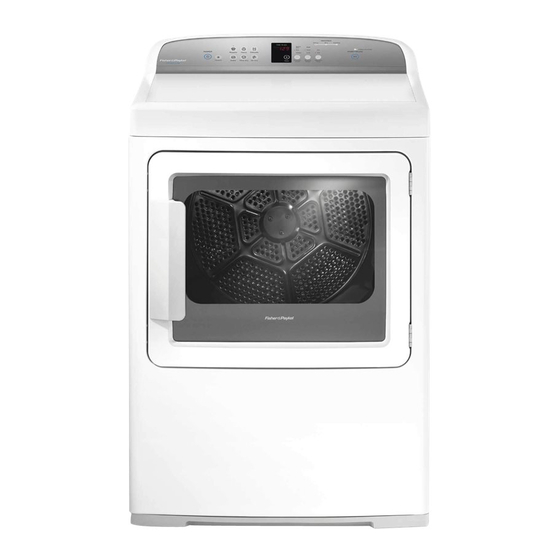
DG7027G1
Gas Dryer With White Steel Top
White
White powder-coated steel
42-43''
27''
29½''
52½''
Gas
3
SmartTouch™ Control Panel
Stainless Steel
Yes
Yes
Yes
Yes
Yes
Yes
Yes
7.0
6
No
Yes
Yes
Yes
Yes
Yes
Yes
4 - Left (2), bottom (1) and rear (1)
Entire Appliance; In-Home; Parts & Labour
Advertisement
Table of Contents

Related Manuals for Fisher & Paykel DG7027G1


Summary of Contents for Fisher & Paykel DG7027G1
- Page 1 DG7027G1 Gas Dryer With White Steel Top Exterior Appearence Color White White powder-coated steel Dimensions Overall Height (in.) 42-43'' Overall Width (in.) 27'' Overall Depth (in.) (door closed) 29½'' Overall Depth (in.) (90° door open ) 52½'' Features Energy Source...
- Page 2 Installation instructions Materials: 4” (102 mm) diameter rigid metal duct (recommended). ■ ■ 4” (102 mm) diameter UL-listed flexible metal duct (if needed). ■ ■ 4” (102 mm) diameter metal elbow(s). ■ ■ Flexible metal gas line connector (for gas connections only). ■ ■ Duct or spring clamps (2). ■...
- Page 3 Installation instructions Unpacking To ensure the best performance from the dryer, please follow the instructions below. WARNING! Excess Weight Hazard Use two or more people to move and install the dryer. Failure to do so can result in back or other injury. Important! Only remove the packaging at the customer’s premises.
-
Page 4: Location Requirements
Installation instructions Location requirements WARNING! Explosion Hazard Keep flammable materials and vapors, such as gasoline, away from the dryer. Place dryer at least 18” (460 mm) above the floor for a garage installation. Failure to do so can result in death, explosion, fire, or burns. The dryer must be installed or stored in an area which is not exposed to water or weather. - Page 5 Installation instructions Minimum clearance required other than alcove or closet installation Allow sufficient room behind the dryer for the exhaust. The air intake is at the rear of the dryer. Ensure that there is a sufficient air passage on each side of the dryer for intake air. The minimum clearance to combustible surfaces and for air openings are: 1”...
- Page 6 Installation instructions Requirements for alcove or closet installation Your dryer is approved for installation in an alcove or closet (as specified on the dryer back). WARNING! When installing a dryer in a closet alcove it MUST be exhausted to the outdoors. No other fuel burning appliance can be installed in the same closet or alcove.
-
Page 7: Residential Garage Installation
Installation instructions Requirements for alcove or closet installation continued The closet should be vented to the outdoors to prevent gas pocketing in case of a gas leak in the ■ ■ supply line. No other fuel-burning appliance shall be installed in the same closet with the dryer (gas models ■... - Page 8 Installation instructions Connecting a gas dryer (skip for electric dryer) Refer to page 7 for tools required. Note: installation and service of this dryer must be performed by a qualified installer, service agency or the gas supplier. Gas supply and installation requirements In the Commonwealth of Massachusetts: Installation of the dryer must be completed by a plumber or gas fitter licensed by the state.
- Page 9 Installation instructions WARNING! To Reduce the Risk of Fire, Electrical Shock and Personal Injury: Before connecting the dryer turn off circuit breaker(s) or remove the dryer’s circuit fuses at its electrical box. Ensure the power cord is unplugged from the wall socket. Ensure the gas shut off valve in the supply line is OFF.
-
Page 10: Elevation Adjustment
Installation instructions Elevation adjustment The input ratings of gas operated clothes dryers are based on their operation at sea level, and ■ ■ need not be adjusted for operation at or below 2000 ft. (610 m) elevation. For operation at elevations above 2000 feet (610 m), input ratings should be reduced at a rate of four percent per 1000 feet (305 m) elevation above sea level. - Page 11 Installation instructions Connecting the dryer to the gas supply Gas connection parts Ensure you have the following parts before installing the dryer. Adapter New metal flexible gas line connector 1/8” NPT pipe plug for checking gas inlet pressure Adapter Shut-off valve Elbow 3/8”...
-
Page 12: Connecting To Supply
Installation instructions Connecting to supply Apply pipe Plugged compound to Tapping all male threads Using two adjustable wrenches tighten all Shut-off valve connections Fig.10 Connecting supply Fig.11 Tightening supply connections Important! Do not over tighten the connections. Test for gas leaks WARNING! NEVER use an open flame to test for gas leaks. - Page 13 Installation instructions WARNING! Fire and Poisoning Hazard Gas leaks cannot always be detected by the sense of smell. Use of an approved UL or CSA gas detector is recommended. If a gas leak is detected follow the “What to do if you smell gas” instructions, stated on the inside font cover of this user guide.
- Page 14 Installation instructions Electrical connection information for gas dryers WARNING! Electrical Shock Hazard Make sure appliance is wired or plugged into a grounded outlet. Improper connection of the equipment-grounding conductor can result in a risk of electric shock. Check with a qualified electrician or service person if you are in doubt as to whether the appliance is properly grounded.
- Page 15 Installation instructions Connecting an electric dryer (skip for gas dryers) – in the United States only Refer to page 7 for tools required. Electrical requirements (electric models only) WARNING! To reduce the risk of fire, electrical shock & personal injury: The appliance must be correctly grounded electrically, in accordance with all local codes and ordinances.
- Page 16 Installation instructions If your outlet looks like this Choose this power supply cord 3-wire (NEMA type 10-30R) (See 3-wire connection) 4-wire (NEMA type 14-30R) (See 4-wire connection) If a power cord is used, this must be plugged into a 30 amp socket only. ■...
- Page 17 Installation instructions Connecting the dryer using 4-wire connection (must be used for mobile home installation) Note: the National Electrical Code requires that new constructions use a 4-wire connection to an electric dryer (effective as of January 1, 1996). Where local codes do not permit grounding through the neutral, a 4-wire cord must also be used.
- Page 18 Installation instructions Connecting the dryer using 3-wire connection Important! DO NOT use in Canada. ■ ■ DO NOT use for Mobile home installations, on new constructions, or on recreational vehicles. ■ ■ NOT for use in areas where local codes prohibit grounding through the neutral conduction. ■...
-
Page 19: Grounding Instructions
Installation instructions Connecting an electric dryer (skip for gas dryers) – in Canada only Electrical requirements (electric models only) WARNING! Electric Shock Hazard Plug appliance into grounded 4 prong outlet. Failure to do so can result in death or electric shock. Note: the wiring diagram is located in the control console. -
Page 20: Exhausting The Dryer
Installation instructions Exhausting the dryer Refer to page 7 for tools required. WARNING! Fire Hazard The dryer must be vented to the outdoors. Use rigid or thick wall flexible metal exhaust duct only. Do not use a plastic exhaust duct. Do not use a metal foil exhaust duct. - Page 21 Installation instructions Dimensions Exhaust outlet location Exhaust outlet 11 ¾” (298 mm) Note: add to vertical dimension the distance between cabinet bottom to floor Fig.16 Exhaust outlet dimensions Before you start If required, remove and discard of all existing plastic or metal foil duct. Replace this with ■...
- Page 22 Installation instructions Exhaust system setup Hood or wall cap Ensure the exhaust duct ends with a vent hood 12” min. ■ ■ with a swing out damper to prevent back drafts (305 mm) and entry of wildlife. Ensure there is minimal resistance to the exhaust ■...
- Page 23 Installation instructions Sealing of joints All joints must be tightly sealed to avoid leaks. ■ ■ The male end of each section of duct must be installed away from the dryer. ■ ■ Do not use screws or fasteners that extend into the duct to secure the joint as lint will ■...
- Page 24 Installation instructions UL-listed flexible metal (foil-type) transition duct Connecting the dryer to the house vent using flexible metal (foil-type) duct maybe required in ■ ■ some installations. A UL-listed flexible metal (foil-type) duct can ONLY be used where: rigid metal or flexible metal (semi-rigid) ducting cannot be used, AND ■...
- Page 25 Installation instructions For transition venting (dryer to wall): Elbows DO cut duct as short as possible DO use elbows when turns and install straight into wall are necessary Fig.20 Correct venting installation DO NOT: DO NOT bend or collapse ducting DO NOT use excessive exhaust length Use elbows if turns are necessary Cut duct as short as possible...
- Page 26 Installation instructions Exhaust Length Maximum length of exhaust duct The maximum length of the exhaust duct system depends upon: The type of ducts used (rigid or thick-walled flexible metal). ■ ■ The number of elbows or bends used. ■ ■ The type of exhaust hood (wall cap).
- Page 27 Installation instructions Preferred 4” (102 mm) Hoods 4” Dia (102 mm) 4” Dia (102 mm) 4” (102 mm) When you have a 4” (102 mm) Hood Maximum length of 4” (102 mm) diameter metal duct. Number of 90˚ Flexible metal Rigid metal elbows/bends (fully extended)
- Page 28 Installation instructions Standard rear exhaust We strongly recommend the use of rigid metal exhaust duct. We recommend you install your dryer first, before installing your washer. This will allow you easier access for connecting the exhaust. Place the end of the exhaust duct on the outlet at the rear of the dryer. Secure with duct tape or a hosed clamp.
- Page 29 Installation instructions Dryer exhaust to right, left or bottom of cabinet WARNING! Before performing this exhaust installation, be sure to disconnect the dryer from its electrical supply. Protect your hands and arms from sharp edges when working inside the cabinet. Be sure to wear gloves. Important! Dryer exhaust to right of cabinet (electric models only).
- Page 30 Installation instructions Adding shortened duct section Connect portion “A” of the original length of duct to the blower housing, ensuring the shortened duct is aligned with the tab in the base. Use the screw saved previously to secure the duct in place through the tab on the dryer base.
- Page 31 Installation instructions Adding ducting for exhaust to the right or left side of the cabinet Assemble a 4” (102 mm) elbow with a 4” (102 mm) length of duct. Secure the joint with duct tape. ■ ■ Insert the elbow end of the duct assembly carefully through the side opening, and connect this ■...
- Page 32 Installation instructions Adding elbow for exhaust through bottom of cabinet Insert the elbow section of the duct through the rear opening and connect it to the dryer ■ ■ internal duct. Secure the joint between the internal duct and elbow with duct tape, as shown in Figure 28 ■...
-
Page 33: Water Connection (For Selected Models With Steam Cycles)
Installation instructions Water connection (for selected models with Steam cycles) Supply requirements The hot and cold faucets MUST be installed no further than 42” (1070 mm) from the washer’s inlet supply. Faucets need to be ¾” (19 mm) so the inlet hoses can be connected correctly. Inlet water pressure required: Min. - Page 34 Installation instructions Check that the washer inlet hose (which has been removed from the faucet) has a flat washer or filter washer fitted. If not insert a flat washer and connect the hose to one of the male couplings on the “Y” connector. Take the long inlet hose and insert a flat washer into the straight female coupling and connect it to the other male coupling on the “Y”...
-
Page 35: Reversing The Door
Installation instructions Reversing the door Tools required: Standard #2 Phillips screwdriver. ■ ■ Tape-tipped putty knife. ■ ■ Needle-nosed pliers. ■ ■ Remove the plug from the power outlet. Open the door and remove the blanking plugs opposite the hinges. Retain the blanking plugs for Step 4. - Page 36 Installation instructions To invert the direction of the door panel, lay the door face down on a safe, protected surface and remove the four screws from the hinges. Fig.35 Removing screws from the hinges Separate the door panel from the inside of the door by removing the six screws, as shown in Figure 36.
- Page 37 Installation instructions Reattach the hinges on the opposite side to the door handle, using the same four screws on the hinge retained from removing the hinges in Step 5. Fig.38 Fixing hinges to opposite side Important! Check the position of the hinge as shown in Figure 38. To change the direction of the door strikes, unscrew both the cover plate and the strike plate (the strike plate being the plate with the metal part protruding).
-
Page 38: Leveling The Dryer
Installation instructions Leveling the dryer Position the dryer near the final location. Adjust the four leveling legs (wind up or down) at the corners as needed, to ensure the dryer matches the height of the washer and is level from side to side and front to back. -
Page 39: Installation Checklist
Installation instructions Installation checklist 1. Packaging Have all of the packaging materials been removed, and disposed of responsibly? Remove the accessories from the drum. 2. Parts Check that all parts have been installed. 3. Tools Check all tools are present. 4. -
Page 40: Turning The Dryer On
Installation instructions Additionally for electric dryer models only, check: Dryer is plugged or directly wired into an approved fitting, and is properly grounded. ■ ■ Dryer starts, heats, cools and shuts off. ■ ■ Customer has been shown how to use the dryer. ■... -
Page 41: Drum Light Replacement
Installation instructions Servicing Important! Label all wires prior to disconnection when servicing controls. Wiring errors can cause improper and dangerous operation after servicing/installation. For service and other information, refer to the “How to get service” section in the back of this book (refer to page 86).
Need help?
Do you have a question about the DG7027G1 and is the answer not in the manual?
Questions and answers
WHAT IS THE AMPERAGE