Table of Contents
Advertisement
Quick Links
Advertisement
Table of Contents

Related Manuals for IEI Technology NANO-GX2


Summary of Contents for IEI Technology NANO-GX2
- Page 1 NANO-GX2 EPIC NANO Motherboard Page i...
- Page 2 NANO-GX2 EPIC NANO Motherboard Revision Date Version Changes May, 2008 1.00 Initial release Page ii...
- Page 3 NANO-GX2 EPIC NANO Motherboard Copyright COPYRIGHT NOTICE The information in this document is subject to change without prior notice in order to improve reliability, design and function and does not represent a commitment on the part of the manufacturer. In no event will the manufacturer be liable for direct, indirect, special, incidental, or consequential damages arising out of the use or inability to use the product or documentation, even if advised of the possibility of such damages.
- Page 4 Cautionary messages should also be heeded to help reduce the chance of losing data or damaging the NANO-GX2. Cautions are easy to recognize. The word “caution” is written as “CAUTION,” both capitalized and bold and is followed. The text is the cautionary message.
- Page 5 “NOTE,” both capitalized and bold and is followed by text. The text is the cautionary message. A note message is shown below: NOTE: This is an example of a note message. Notes should always be read. Notes contain critical information about the NANO-GX2. Please take note messages seriously. Page v...
- Page 6 NANO-GX2 from or contact an IEI sales representative directly. To contact an IEI sales representative, please send an email to sales@iei.com.tw. The items listed below should all be included in the NANO-GX2 package. 1 x NANO-GX2 single board computer 1 x 44-pin IDE cable...
-
Page 7: Table Of Contents
NANO-GX2 EPIC NANO Motherboard Table of Contents 1 INTRODUCTION......................1 1.1 CPU B .................... 2 OARD VERVIEW 1.1.1 Applications ....................... 2 1.1.2 Benefits....................... 2 1.1.3 Features ......................3 1.2 G ....................4 ENERAL VERVIEW 1.2.1 CPU Board Connectors ..................5 1.2.2 Technical Specifications.................. - Page 8 HECKLIST 3.3.1 Package Contents..................... 31 4 PINOUTS........................33 4.1 P ..............34 ERIPHERAL NTERFACE ONNECTORS 4.1.1 NANO-GX2 Layout ..................34 4.1.2 Peripheral Interface Connectors ..............35 4.1.3 External Interface Panel Connectors............... 36 4.2 I ..............36 NTERNAL ERIPHERAL ONNECTORS 4.2.1 Audio Connector ....................36 4.2.2 CD In Connector....................
- Page 9 NANO-GX2 EPIC NANO Motherboard 4.3.6 VGA Connector ....................56 5 INSTALLATION ......................59 5.1 A ..................60 STATIC RECAUTIONS 5.2 I ................61 NSTALLATION ONSIDERATIONS 5.2.1 Installation Notices ..................61 5.2.2 Installation Checklist ..................62 5.2.3 CF Card Installation ..................63 5.3 J...
- Page 10 NANO-GX2 EPIC NANO Motherboard 6.3 A BIOS F ..................89 DVANCED EATURES 6.4 A ................93 DVANCED HIPSET EATURES 6.5 I ..................95 NTEGRATED ERIPHERALS 6.6 P .................. 98 OWER ANAGEMENT ETUP 6.7 P P/PCI C ................... 100 ONFIGURATIONS 6.8 PC H ....................
- Page 11 NANO-GX2 EPIC NANO Motherboard G.1 H IPB P AZARDOUS ATERIALS ISCLOSURE ABLE FOR RODUCTS ERTIFIED AS HS C 2002/95/EC W ........144 OMPLIANT NDER ITHOUT ERCURY H AC'97 AUDIO CODEC .................... 147 H.1 I ..................... 148 NTRODUCTION H.1.1 Accessing the AC’97 CODEC ............... 148 H.1.2 Driver Installation..................
- Page 12 Figure 1-1: NANO-GX2 ........................2 Figure 1-2: Overview (Front Side) ....................4 Figure 1-3: Overview (Solder Side) ....................5 Figure 2-1: NANO-GX2 Dimensions (mm) ..................10 Figure 2-2: External Interface Panel Dimensions (mm) ............11 Figure 2-3: Data Flow Block Diagram ..................12 Figure 2-4: AMD Geode GX......................13 Figure 2-5: Graphics Support......................14...
- Page 13 NANO-GX2 EPIC NANO Motherboard Figure 4-12: Reset Button Connector Locations...............50 Figure 4-13: USB Connector Pinout Locations .................51 Figure 4-14: NANO-GX2 On-board External Interface Connectors .........52 Figure 4-15: Ethernet Connector....................53 Figure 4-16: PS/2 Connector .......................54 Figure 4-17: Serial Port Pinout Locations ..................56 Figure 4-18: VGA1 Connector .....................57...
- Page 14 NANO-GX2 EPIC NANO Motherboard List of Tables Table 1-1: Technical Specifications....................7 Table 2-1: Geode™ GX Graphics Processor Features .............15 Table 2-2: Supported HDD Specifications..................22 Table 2-3: Power Consumption....................28 Table 3-1: Package List Contents ....................32 Table 4-1: Peripheral Interface Connectors ................36 Table 4-2: Rear Panel Connectors ....................36...
- Page 15 NANO-GX2 EPIC NANO Motherboard Table 6-1: BIOS Navigation Keys ....................81 Page xv...
- Page 16 NANO-GX2 EPIC NANO Motherboard BIOS Menus BIOS Menu 1: Award BIOS CMOS Setup Utility ................82 BIOS Menu 2: Standard CMOS Features..................84 BIOS Menu 3: IDE Channel Master .....................86 BIOS Menu 4: Advanced BIOS Features ..................89 BIOS Menu 5: Advanced Chipset Features................93 BIOS Menu 6: Integrated Peripherals ..................95...
-
Page 17: Introduction
NANO-GX2 EPIC NANO Motherboard Chapter Introduction Page 1... -
Page 18: Cpu Board Overview
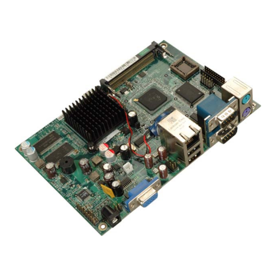
1.1 CPU Board Overview Figure 1-1: NANO-GX2 The EPIC form factor NANO-GX2 is a highly integrated CPU card for embedded computers, specifically optimized for multi-media applications requiring minimum installation space. The NANO-GX2 is particularly suitable for low power and fan-less applications. -
Page 19: Features
BIOS watchdog timer detects that the system is no longer operating small form factor ideally suited for thin client applications 1.1.3 Features Some of the NANO-GX2 motherboard features are listed below: EPIC form factor RoHS compliant Embedded AMD Geode™ GX 466 CPU... -
Page 20: General Overview
NANO-GX2 EPIC NANO Motherboard 1.2 General Overview Figure 1-2: Overview (Front Side) Page 4... -
Page 21: Cpu Board Connectors
1 x Power and HDD LED Connector............48 1 x Power Button Connector ..............49 1 x Reset Button Connector..............50 2 x USB Connectors................50 The NANO-GX2 has the following external peripheral interface connectors: 1 x Ethernet Connector ................52 Page 5... -
Page 22: Technical Specifications
The location of these connectors on the motherboard can be seen in Figure 4-1. These connectors are fully described in Chapter 4. 1.2.2 Technical Specifications NANO-GX2 motherboard technical specifications are listed in Table 1-1. Detailed descriptions of each specification can be found in Chapter 2. SPECIFICATION... -
Page 23: Table 1-1: Technical Specifications
NANO-GX2 EPIC NANO Motherboard SPECIFICATION NANO-GX2 Two external USB 2.0 ports USB2.0 One internal USB 2.0 pin header (for two USB 2.0 ports) One 44-pin IDE connects to two Ultra ATA33/66/100 devices One PS/2 connector for keyboard KB/MS One PS/2 connector for mouse Software programmable 1-255 sec. - Page 24 NANO-GX2 EPIC NANO Motherboard THIS PAGE IS INTENTIONALLY LEFT BLANK Page 8...
-
Page 25: Detailed Specifications
NANO-GX2 EPIC NANO Motherboard Chapter Detailed Specifications Page 9... -
Page 26: Overview
NANO-GX2 EPIC NANO Motherboard 2.1 Overview This chapter describes the specifications and on-board features of the NANO-GX2 in detail. 2.2 Dimensions 2.2.1 Board Dimensions The dimensions of the board are listed below: Length: 165mm Width: 115mm Figure 2-1: NANO-GX2 Dimensions (mm) 2.2.2 External Interface Panel Dimensions... -
Page 27: Figure 2-2: External Interface Panel Dimensions (Mm)
NANO-GX2 EPIC NANO Motherboard Figure 2-2: External Interface Panel Dimensions (mm) Page 11... -
Page 28: Data Flow
NANO-GX2 EPIC NANO Motherboard 2.3 Data Flow The NANO-GX2 motherboard comes with an AMD Geode™ GX 466 and an AMD Geode™ CS5536 linked together by the GeodeLink™ Interface Unit. Figure 2-3 shows the data flow between the system chipset, the CPU and other components installed on the motherboard. -
Page 29: Embedded Amd Geode™ Gx 466 Cpu
NANO-GX2 EPIC NANO Motherboard 2.4 Embedded AMD Geode™ GX 466 CPU The NANO-GX2 series motherboards all come with a preinstalled AMD Geode™ GX 466 333 MHz CPU. Figure 2-4: AMD Geode GX The specifications for the 333 MHz AMD Geode™ GX 466 are listed below. -
Page 30: Graphics Support
Active hardware power management Software power management Low power I/O 2.5 Graphics Support Figure 2-5: Graphics Support Table 2-1 lists the NANO-GX2 graphics processor features. Feature AMD Geode™ GX 466 Processor Color Depth 32 (24 plus 8 alpha blending) ROPs... -
Page 31: Memory Support
VGA Support Decodes VGA Register Table 2-1: Geode™ GX Graphics Processor Features 2.6 Memory Support 128 MB DDR RAM is embedded on the NANO-GX2. An option of 256 MB of DDR RAM embedded in the board is available. Page 15... -
Page 32: Geodelink™ Pci Bridge
NANO-GX2 EPIC NANO Motherboard Figure 2-6: Onboard DDR RAM 2.7 GeodeLink™ PCI Bridge 2.7.1 GeodeLink™ Figure 2-7: GeodeLink™ The GeodeLink™ PCI Bridge (GLPCI) module provides a PCI interface for GeodeLink Interface Unit-based designs. The GLPCI module is composed of six major blocks:... -
Page 33: 10/100 Mb/S Ethernet
NANO-GX2 EPIC NANO Motherboard PCI Version 2.2 compliance 32-bit, 66 MHz PCI bus operation Target support for fast back-to-back transactions Arbiter support for three external PCI bus masters Write gathering and write posting for in-bound write requests Virtual PCI header support... -
Page 34: Mini Pci Expansion Slot
2.5/3.3 V power supply with 5V tolerant I/Os 2.7.3 Mini PCI Expansion Slot The Mini PCI expansion slot allows a Mini PCI card to be attached to the NANO-GX2. The Mini PCI slot is connected to the GeodeLink™ PCI interface. -
Page 35: Amd Geode™ Cs5536 System Chipset
NANO-GX2 EPIC NANO Motherboard 2.8 AMD Geode™ CS5536 System Chipset The NANO-GX2 motherboard has an AMD Geode™ CS5536 chipset installed. The AMD Geode™ CS5536 is a companion device for the AMD Geode™ GX 466 to create a high-performance, low-power x86 solution for embedded applications. -
Page 36: Geodelink™ Interface Unit
NANO-GX2 EPIC NANO Motherboard Supports both USB 1.1 and USB 2.0 4 host ports Audio Codec 97 (AC97) Controller AC97 specification v2.3 compliant interface to multiple audio codecs: Serial In, Serial Out, Sync Out, Bit Clock In Legacy “PC Beep” support... -
Page 37: Controller
NANO-GX2 EPIC NANO Motherboard 2.8.2 ATA-6 Controller Figure 2-11: IDE Interface The single NANO-GX2 IDE connector supports two ATA-6 HDDs and a CompactFlash® disk connected to the IDE interface. The CompactFlash® slot support both Type I and Type II CompactFlash® cards. -
Page 38: Ac'97 Controller
NANO-GX2 EPIC NANO Motherboard Specification Ultra ATA/100 Ultra ATA/66 Ultra ATA/33 100MB/s 66MB/s 33MB/s DMA/UDMA Max Transfer Controller Interface Table 2-2: Supported HDD Specifications 2.8.3 AC’97 Controller The AC’97 specification v2.3 compliant controller on the chipset is interfaced to a 20-bit DAC and 18-bit ADC full-duplex AC'97 2.3 stereo Realtek ALC203 codec. - Page 39 NANO-GX2 EPIC NANO Motherboard 14.318MHz -> 24.576MHz PLL saves crystal 12.288MHz BITCLK input can be consumed Integrated PCBEEP generator to save buzzer Interrupt capability Page registers and Analog Plug & Play Support of S/PDIF out is fully compliant with AC'97 rev2.3 specifications...
-
Page 40: Flash Interface
2.8.4 Flash Interface Figure 2-13: CompactFlash® Slot The NANO-GX2 CompactFlash® socket supports standard CF Type I and CF Type II cards. The chipset flash interface is multiplexed with an IDE interface and can be connected to an array of industry standard NAND Flash or NOR Flash devices. -
Page 41: Usb Controller
2.8.5 USB Controller Figure 2-14: USB Ports Four external USB ports on the NANO-GX2 board are interfaced to the chipset USB controller. Four USB 1.1 or USB 2.0 devices can be connected simultaneously to the NANO-GX2. The chipset USB controller has the following specifications: 4 USB ports USB 1.1 and USB 2.0 compliant... -
Page 42: Serial Communications
NANO-GX2 EPIC NANO Motherboard 2.8.6 Serial Communications Figure 2-15: Serial Communications Two high-speed UART serial port connectors (RS-232) are connected to the system chipset low pin count (LPC) port via the LPC bus. The specifications for the serial ports are listed below. -
Page 43: Bios
2.8.8 BIOS Figure 2-16: BIOS The BIOS flash memory chip on the NANO-GX2 has a licensed copy of AWARD BIOS loaded onto it. The BIOS flash memory chip is connected to the chipset via the LPC bus. The flash BIOS features are listed below:... -
Page 44: Power Consumption
Northbridge and Southbridge chipsets to ensure the operating temperature of these chips remain low. 2.9.3 Power Consumption Table 2-3 shows the power consumption parameters for the NANO-GX2 running with 256 MB of memory. Voltage Current... -
Page 45: Unpacking
NANO-GX2 EPIC NANO Motherboard Chapter Unpacking Page 29... -
Page 46: Anti-Static Precautions
When the NANO-GX2 is unpacked, please do the following: Follow the anti-static precautions outlined in Section 3.1. Make sure the packing box is facing upwards so the NANO-GX2 does not fall out of the box. Make sure all the components shown in Section 3.3 are present. -
Page 47: Unpacking Checklist
If some of the components listed in the checklist below are missing, please do not proceed with the installation. Contact the IEI reseller or vendor you purchased the NANO-GX2 from or contact an IEI sales representative directly. To contact an IEI sales representative, please send an email to sales@iei.com.tw. -
Page 48: Table 3-1: Package List Contents
NANO-GX2 EPIC NANO Motherboard Quantity Item Image Dual USB port cable (P/N: 32000-044300-RS) Mini jumper pack Quick Installation Guide Utility CD Table 3-1: Package List Contents Page 32... -
Page 49: Pinouts
NANO-GX2 EPIC NANO Motherboard Chapter Pinouts Page 33... -
Page 50: Peripheral Interface Connectors
NANO-GX2 EPIC NANO Motherboard 4.1 Peripheral Interface Connectors Section 4.1.2 shows peripheral interface connector locations. Section 4.1.2 lists all the peripheral interface connectors seen in Section 4.1.2. 4.1.1 NANO-GX2 Layout Figure 4-1 shows the on-board peripheral connectors, rear panel peripheral connectors and on-board jumpers. -
Page 51: Peripheral Interface Connectors
NANO-GX2 EPIC NANO Motherboard Figure 4-2: Connector and Jumper Locations (Solder Side) 4.1.2 Peripheral Interface Connectors Table 4-1 shows a list of the peripheral interface connectors on the NANO-GX2. Detailed descriptions of these connectors can be found below. Connector Type... -
Page 52: External Interface Panel Connectors
USB connectors 8-pin header USB1 Table 4-1: Peripheral Interface Connectors 4.1.3 External Interface Panel Connectors Table 4-2 lists the rear panel connectors on the NANO-GX2. Detailed descriptions of these connectors can be found in Section 4.1. Connector Type Label Ethernet connector... -
Page 53: Cd In Connector
NANO-GX2 EPIC NANO Motherboard The 10-pin audio connector is connected to external audio devices including speakers and microphones for the input and output of audio signals to and from the system. Figure 4-3: Audio Connector Location PIN NO. DESCRIPTION PIN NO. -
Page 54: Compactflash ® Socket
NANO-GX2 EPIC NANO Motherboard Figure 4-4: Audio CD In Connector Location PIN NO. DESCRIPTION CD Signal (Left) Ground Ground CD Signal (Right) Table 4-4: Audio CD In Connector Pinouts ® 4.2.3 CompactFlash Socket CN Label: CF1 (solder side) CN Type:... -
Page 55: Figure 4-5: Cf Card Socket Location
NANO-GX2 EPIC NANO Motherboard Figure 4-5: CF Card Socket Location PIN NO. DESCRIPTION PIN NO. DESCRIPTION GROUND DATA 3 DATA 11 DATA 4 DATA 12 DATA 5 DATA 13 DATA 6 DATA 14 DATA 7 DATA 15 HDC_CS0# HDC_CS1 Page 39... -
Page 56: Digital I/O Connector
NANO-GX2 EPIC NANO Motherboard PIN NO. DESCRIPTION PIN NO. DESCRIPTION GROUND IOR# IOW# VCC5 IRQ15 VCC5 VCC5 CSEL HDD_RESET DACK# HDD_ACTIVE# DATA 0 CABLEID DATA 1 DATA 8 DATA 2 DATA 9 DATA 10 GROUND Table 4-5: CF Card Socket Pinouts 4.2.4 Digital I/O Connector... -
Page 57: Fan Connector
NANO-GX2 EPIC NANO Motherboard Figure 4-6: Digital I/O Connector Locations PIN NO. DESCRIPTION PIN NO. DESCRIPTION VCC5 Output 0 Output 1 Output 2 Output 3 Input 0 Input 1 Input 2 Input 3 Table 4-6: Digital I/O Connector Pinouts 4.2.5 Fan Connector... -
Page 58: Ide Connector
Table 4-7: Fan Connector Pinouts 4.2.6 IDE Connector CN Label: HDD1 CN Type: 44-pin box header (2x22) CN Location: See Figure 4-8 CN Pinouts: See Table 4-8 One 44-pin IDE device connector on the NANO-GX2 supports connectivity to two hard disk drives. Page 42... -
Page 59: Figure 4-8: Ide Connector Location
NANO-GX2 EPIC NANO Motherboard Figure 4-8: IDE Connector Location PIN NO. DESCRIPTION PIN NO. DESCRIPTION RESET# GROUND DATA 7 DATA 8 DATA 6 DATA 9 DATA 5 DATA 10 DATA 4 DATA 11 DATA 3 DATA 12 DATA 2 DATA 13... -
Page 60: Mini Pci Slot
NANO-GX2 EPIC NANO Motherboard PIN NO. DESCRIPTION PIN NO. DESCRIPTION DATA 0 DATA 15 GROUND IDE DRQ GROUND IOW# GROUND IOR# GROUND IDE CHRDY GROUND IDE DACK GROUND–DEFAULT INTERRUPT HDC CS0# HDC CS1# HDD ACTIVE# GROUND GROUND Table 4-8: IDE Connector Pinouts 4.2.7 Mini PCI Slot... -
Page 61: Figure 4-9: Mini Pci Slot Location
NANO-GX2 EPIC NANO Motherboard Figure 4-9: Mini PCI Slot Location Page 45... - Page 62 NANO-GX2 EPIC NANO Motherboard PIN NO. DESCRIPTION PIN NO. DESCRIPTION PINTD# VCC5 VCC3 PINTC# VCC3SB CLK_MPCI PCI_RST1# VCC3 PCI_REQ2# PCI_GNT2# VCC3 PAD31 PPME# PAD29 PAD30 PAD27 VCC3 PAD25 PAD28 PAD26 PC/BE3# PAD24 PAD23 PAD29 PAD21 PAD22 PAD19 PAD20 PPAR Page 46...
- Page 63 NANO-GX2 EPIC NANO Motherboard PIN NO. DESCRIPTION PIN NO. DESCRIPTION PAD17 PAD18 PC/BE2# PAD16 PIRDY# VCC3 PFRAME# PTRDY# SERR# PSTOP# VCC3 PERR# PDEVSEL# PC/BE1# PAD14 PAD15 PAD13 PAD12 PAD11 PAD10 PAD9 PAD8 PC/BE0# PAD7 VCC3 VCC3 PAD6 PAD5 PAD4 PAD2...
-
Page 64: Power And Hdd Led Connector
NANO-GX2 EPIC NANO Motherboard PIN NO. DESCRIPTION PIN NO. DESCRIPTION VCC3SB Table 4-9: Mini PCI Slot Pinouts 4.2.8 Power and HDD LED Connector CN Label: LED1 CN Type: 6-pin wafer See Figure 4-10 CN Location: See Table 4-10 CN Pinouts: The Power and HDD LED Connector connects to the computer’s power and hard drive... -
Page 65: Power Button Connector
NANO-GX2 EPIC NANO Motherboard PIN NO. DESCRIPTION GROUND PWRLED+ PWRLED- Table 4-10: Power and HDD LED Connector Pinouts 4.2.9 Power Button Connector CN Label: 2-pin wafer CN Type: CN Location: See Figure 4-11 CN Pinouts: See Table 4-11 The power button connector is connected to a power switch on the system chassis to enable users to turn the system on and off. -
Page 66: Reset Button Connector
NANO-GX2 EPIC NANO Motherboard 4.2.10 Reset Button Connector CN Label: 2-pin wafer (1x2) CN Type: CN Location: See Figure 4-12 CN Pinouts: See Table 4-12 The reset button connector is connected to a reset switch on the system chassis to enable users to reboot the system when the system is turned on. -
Page 67: External Interface Connectors
Table 4-13: USB Port Connector Pinouts 4.3 External Interface Connectors Figure 4-14 shows the NANO-GX2 motherboard external interface connectors. The NANO-GX2 on-board external interface connectors are listed below and shown in Figure 4-14: 4.3.1 Ethernet Connector 4.3.2 Keyboard and Mouse Connector 4.3.3 Power Input Connector... -
Page 68: Ethernet Connector
NANO-GX2 EPIC NANO Motherboard 4.3.6 VGA Connector Figure 4-14: NANO-GX2 On-board External Interface Connectors 4.3.1 Ethernet Connector CN Label: LAN_USB1 CN Type: RJ-45 See Figure 4-14 CN Location: CN Pinouts: See Table 4-14 A 10/100 Mbps connection can be made between the Ethernet connector and a Local Area Network (LAN) through a network hub. -
Page 69: Keyboard And Mouse Connector
CN Label: KBMS1 PS/2 CN Type: CN Location: See Figure 4-14 CN Pinouts: See Table 4-16 and Figure 4-16 The NANO-GX2 has two PS/2 connectors on the mounting bracket for easy connection to a PS/2 keyboard and PS/2 mouse. Page 53... -
Page 70: Power Input Connector
CN Location: See Figure 4-14 CN Pinouts: See Table 4-17 The power input connector is for connecting a 5 V power supply to the NANO-GX2. The 5 V DC power jack is connected directly to the power input connector. Page 54... -
Page 71: Serial Port Connectors
NANO-GX2 EPIC NANO Motherboard PIN NO. DESCRIPTION GROUND GROUND Power IN(+12V) Power IN(+12V) Table 4-17: Power Input Connector Pinouts 4.3.4 RS-232 Serial Port Connectors CN Label: COM1 CN Type: Two RS-232 connectors CN Location: See Figure 4-14 CN Pinouts: See Table 4-18 and Figure 4-17 The RS-232 serial connector provides serial connection in the RS-232 mode. -
Page 72: Usb Ports
NANO-GX2 EPIC NANO Motherboard Figure 4-17: Serial Port Pinout Locations 4.3.5 USB Ports CN Label: LAN_USB1 CN Type: USB Combo ports CN Location: See Figure 4-14 See Table 4-19 CN Pinouts: The USB combo port provides connectivity to additional USB devices through an adapter cable. -
Page 73: Figure 4-18: Vga1 Connector
NANO-GX2 EPIC NANO Motherboard CN Location: See Figure 4-14 CN Pinouts: See Figure 4-18 and Table 4-20 The standard 15-pin female VGA connector connects to a CRT or LCD monitor. DESCRIPTION DESCRIPTION DESCRIPTION GROUND GREEN GROUND BLUE GROUND HSYNC VSYNC... - Page 74 NANO-GX2 EPIC NANO Motherboard THIS PAGE IS INTENTIONALLY LEFT BLANK Page 58...
-
Page 75: Installation
NANO-GX2 EPIC NANO Motherboard Chapter Installation Page 59... -
Page 76: Anti-Static Precautions
Electrostatic discharge (ESD) can cause serious damage to electronic components, including the NANO-GX2. Dry climates are especially susceptible to ESD. It is therefore critical that whenever the NANO-GX2, or any other electrical component is handled, the following anti-static precautions are strictly adhered to. -
Page 77: Installation Considerations
NANO-GX2 is installed. All installation notices pertaining to the installation of NANO-GX2 should be strictly adhered to. Failing to adhere to these precautions may lead to severe damage of the NANO-GX2 and injury to the person installing the motherboard. 5.2.1 Installation Notices... -
Page 78: Installation Checklist
Allow screws to come in contact with the PCB circuit, connector pins, or its components. 5.2.2 Installation Checklist The following checklist is provided to ensure the NANO-GX2 is properly installed. All the items in the packing list are present A compatible memory module is properly inserted into the slot... -
Page 79: Cf Card Installation
The NANO-GX2 can support both CF Type I cards and CF Type II cards. For the complete specifications of the supported CF cards please refer to Chapter 2. To install the a CF card (Type 1 or Type 2) onto the NANO-GX2, please follow the steps below: Step 1: Locate the CF card socket. -
Page 80: Jumper Settings
OPEN a jumper means removing the plastic clip from a jumper. Before the NANO-GX2 is installed in the system, the jumpers must be set in accordance with the desired configuration. The jumpers on the NANO-GX2 are listed in Table 5-1. Page 64... -
Page 81: At/Atx Power Mode
NANO-GX2 EPIC NANO Motherboard Description Label Type AT/ATX Power Mode Select 2-pin header Board ID 4-pin header CompactFlash® Master/Slave 2-pin header Table 5-1: Jumpers 5.3.1 AT/ATX Power Mode Jumper Label: Jumper Type: 2-pin header Jumper Settings: See Table 5-2 Jumper Location: See Figure 5-2 The Power Mode jumper specifies the systems power mode as AT or ATX. -
Page 82: Board Id
NANO-GX2 EPIC NANO Motherboard 5.3.2 Board ID Jumper Label: 4-pin header Jumper Type: Jumper Settings: See Table 5-3 Jumper Location: See Figure 5-4 The Board ID jumper configures is used to identify how much RAM this model has. The jumper selection options are shown in Table 5-3. The jumper location is shown in Figure 5-3. -
Page 83: Chassis Installation
The NANO-GX2 must be installed in a chassis with ventilation holes on the sides allowing airflow to travel through the heat sink surface. In a system with an individual power supply... -
Page 84: Nano-Gx2 Installation
USB dual port cable Table 5-5: IEI Provided Cables 5.5.1 ATA Flat Cable Connection The ATA 33 flat cable connects the NANO-GX2 to one or two IDE devices. To connect an IDE HDD to the NANO-GX2 please follow the instructions below. Step 1: Locate the IDE connector. -
Page 85: Usb Cable
1 on the connectorStep 0: 5.5.2 USB Cable The NANO-GX2 is shipped with a dual port USB 2.0 cable. To connect the USB cable connector, please follow the steps below. Step 1: Locate the connectors. The locations of the USB connectors are shown in Chapter 3. -
Page 86: Audio Kit Installation
0: 5.5.3 Audio Kit Installation The Audio Kit that came with the NANO-GX2 connects to the 10-pin audio connector on the NANO-GX2. The audio kit consists of three audio jacks. One audio jack, Mic In, connects to a microphone. The remaining two audio jacks, Line-In and Line-Out, connect to two speakers. -
Page 87: External Peripheral Interface Connection
NANO-GX2 EPIC NANO Motherboard Step 1: Locate the audio connector. The location of the 10-pin audio connector is shown in Chapter 3. Step 2: Align pin 1. Align pin 1 on the onboard connector with pin 1 on the audio kit connector. -
Page 88: Keyboard And Mouse
5.6.1 Keyboard and Mouse The NANO-GX2 has a dual PS/2 connector on the external peripheral interface panel. The dual PS/2 connector is used to connect to a keyboard and mouse to the system. Follow the steps below to connect a keyboard and mouse to the NANO-GX2. -
Page 89: Lan
Locate the RJ-45 connectors. The locations of the USB connectors are shown in Chapter 4. Step 2: Align the connectors. Align the RJ-45 connector on the LAN cable with one of the RJ-45 connectors on the NANO-GX2. See Figure 5-9. Page 73... -
Page 90: Serial Device
RJ-45 connector into the on-board RJ-45 connector. Step 0: 5.6.3 Serial Device The NANO-GX2 has a single female DB-9 connector on the external peripheral interface panel for a serial device. Follow the steps below to connect a serial device to the NANO-GX2. -
Page 91: Usb
5.6.4 USB The external USB Series "A" receptacle connectors provide easier and quicker access to external USB devices. Follow the steps below to connect USB devices to the NANO-GX2. Step 1: Locate the USB Series "A" receptacle connectors. The location of the USB Series "A"... -
Page 92: Vga Monitor
Figure 5-11: USB Connector 5.6.5 VGA Monitor The NANO-GX2 has a single female DB-15 connector on the external peripheral interface panel. The DB-15 connector is connected to a CRT or VGA monitor. To connect a monitor to the NANO-GX2, please follow the instructions below. -
Page 93: Figure 5-12: Vga Connector
NANO-GX2 EPIC NANO Motherboard Figure 5-12: VGA Connector Step 4: Secure the connector. Secure the DB-15 VGA connector from the VGA monitor to the external interface by tightening the two retention screws on either side of the connector. Step 0:... - Page 94 NANO-GX2 EPIC NANO Motherboard THIS PAGE IS INTENTIONALLY LEFT BLANK Page 78...
-
Page 95: Bios Setup
NANO-GX2 EPIC NANO Motherboard Chapter BIOS Setup Page 79... -
Page 96: Introduction
NANO-GX2 EPIC NANO Motherboard 6.1 Introduction A licensed copy of Phoenix Award BIOS is preprogrammed into the ROM BIOS. The BIOS setup program allows users to modify the basic system configuration. This chapter describes how to access the BIOS setup program and the configuration options that may be changed. -
Page 97: Getting Help
NANO-GX2 EPIC NANO Motherboard Function General help, only for Status Page Setup Menu and Option Page Setup Menu Item help Previous values for the page menu items Fail-safe defaults for the current page menu items Optimized defaults for the current page menu items... - Page 98 NANO-GX2 EPIC NANO Motherboard BIOS Menu 1: Award BIOS CMOS Setup Utility NOTE: The following sections will completely describe the menus listed below and the configuration options available to users. The following menu options are seen in BIOS Menu 1.
- Page 99 NANO-GX2 EPIC NANO Motherboard Load Fail-Safe Defaults Use the Load Fail-Safe Defaults option to load failsafe default values for each BIOS parameter in the setup menus. Press F6 for this operation on any page. Load Optimized Defaults Use the Load Optimized Defaults option to load optimal default values for each BIOS parameter in the setup menus.
-
Page 100: Standard Cmos Features
NANO-GX2 EPIC NANO Motherboard 6.2 Standard CMOS Features Use the Standard CMOS Features BIOS menu (BIOS Menu 2) to set basic BIOS configuration options. BIOS Menu 2: Standard CMOS Features Date [Day mm:dd:yyyy] Use the Date option to set the system date Time [hh/mm/ss] Use the Time option to set the system time. - Page 101 NANO-GX2 EPIC NANO Motherboard IDE Primary Master IDE Primary Slave IDE device configurations are changed or set in the IDE Configuration menu (BIOS Menu 3). If an IDE device is detected, and one of the above listed two BIOS configuration options is selected, the IDE configuration options shown in Section 6.2.1 appear.
-
Page 102: Ide Primary Master/Slave
NANO-GX2 EPIC NANO Motherboard Total Memory The Total Memory is NOT user configurable. 6.2.1 IDE Primary Master/Slave Use the IDE Primary Master/Slave menu (BIOS Menu 3) to set or change the master/slave IDE configurations. BIOS Menu 3: IDE Channel Master... - Page 103 NANO-GX2 EPIC NANO Motherboard Channel 0 Master Channel 0 Slave Channel 1 Master Channel 0 Slave None If no drives are connected to the IDE channel select this option. Once set, this IDE channel becomes inaccessible and any drives attached to it are undetected.
- Page 104 NANO-GX2 EPIC NANO Motherboard Cylinder The Cylinder specification indicates how many cylinders (tracks) are on the HDD installed in the system. Head The Head specification indicates how many logical heads are on the HDD installed in the system. Precomp The Precomp specification indicates on what track the write precompensation begins.
-
Page 105: Advanced Bios Features
NANO-GX2 EPIC NANO Motherboard 6.3 Advanced BIOS Features Use the Advanced BIOS Features menu (BIOS Menu 4) to configure the CPU and peripheral device configuration options. BIOS Menu 4: Advanced BIOS Features Quick Power On Self Test [Enabled] Use the Quick Power On Self Test option to speed up the POST after the computer is turned on. - Page 106 NANO-GX2 EPIC NANO Motherboard Disabled The system cannot be booted from a remote system EFAULT through the LAN. The system can be booted from a remote system Enabled through the LAN. Boot Device Use the Boot Device options to select the order of the devices the system boots from.
- Page 107 NANO-GX2 EPIC NANO Motherboard Disabled The system does not look for second and third boot devices if the first one is not found. The system looks for second and third boot devices if the Enabled EFAULT first one is not found.
- Page 108 NANO-GX2 EPIC NANO Motherboard Enabled Console redirection enabled Console redirection is disabled Disabled EFAULT Baud Rate [19200] Sets the baud rate for console redirection. The following options are available. 9600 19200 Default 38400 57600 115200 Agent after boot [Disabled] Use the Agent after boot [Disabled] to keep console redirection active after the operating system loads.
-
Page 109: Advanced Chipset Features
NANO-GX2 EPIC NANO Motherboard 6.4 Advanced Chipset Features Use the Advanced Chipset Features menu (BIOS Menu 5) to change chipset configuration options. BIOS Menu 5: Advanced Chipset Features Video Memory Size [8M] Use the Video Memory Size option to determine how much memory is allocated to the video graphics device. - Page 110 NANO-GX2 EPIC NANO Motherboard OnBoard Audio [Enabled] Use the OnBoard Audio option to enable or disable the onboard codec. The onboard codec is disabled. Disabled Enabled The onboard codec is detected and enabled. EFAULT Onboard USB 2.0 [Enabled] The USB 2.0 Controller BIOS option enables or disables the USB 2.0 controller...
-
Page 111: Integrated Peripherals
NANO-GX2 EPIC NANO Motherboard 6.5 Integrated Peripherals Use the Integrated Peripherals menu (BIOS Menu 6) to change the configuration options for the attached peripheral devices. BIOS Menu 6: Integrated Peripherals On-Chip IDE Channel 1 [Enabled] Use the On-Chip IDE Channel 1 option to specify if the system uses the integrated primary IDE channel or not. - Page 112 NANO-GX2 EPIC NANO Motherboard Master Drive PIO Mode Slave Drive PIO Mode Auto The computer selects the correct mode. EFAULT PIO mode 0 selected with a maximum transfer rate of 3.3MBps. Mode 0 Mode 1 PIO mode 1 selected with a maximum transfer rate of 5.2MBps.
- Page 113 NANO-GX2 EPIC NANO Motherboard IDE HDD Block Mode [Enabled] If the drive connected to the system supports block mode, use the IDE HDD Block Mode option to enable the system to detect the optimal number of block read/writes per sector the system IDE drive can support.
-
Page 114: Power Management Setup
NANO-GX2 EPIC NANO Motherboard Onboard Serial Port 2 Mode [Normal] Use the Onboard Serial Port 2 Mode to select the UART mode for the system. Infrared port compliant with IrDA specification IrDA ASK IR Amplitude shift keyed infrared port Normal... - Page 115 NANO-GX2 EPIC NANO Motherboard BIOS Menu 7: Power Management Setup Power Management [ACPI] Use the Power Management option to set the power management type used by the system. Advanced power management (APM) is activated ACPI Advanced Configuration and Power Interface (ACPI) is EFAULT activated.
-
Page 116: Pnp/Pci Configurations
NANO-GX2 EPIC NANO Motherboard Enabled Wake event generated by PCI PME controller activity EFAULT Power-On by Alarm [Disabled] Use the Power-On by Alarm option to specify when the computer is roused from a suspended state. The real time clock (RTC) cannot generate a wake... - Page 117 NANO-GX2 EPIC NANO Motherboard BIOS Menu 8: PnP/PCI Configurations Resources Controlled By [Auto (ESCD)] Use the Resources Controlled By option to either manually configure all the boot and plug and play devices, or allow BIOS to configure these devices automatically. If BIOS is allowed to configure the devices automatically IRQs, DMA and memory base address fields cannot be set manually.
- Page 118 NANO-GX2 EPIC NANO Motherboard BIOS Menu 9: IRQ Resources The IRQ Resources menu has the following options: IRQ-3 assigned to IRQ-4 assigned to IRQ-5 assigned to IRQ-7 assigned to IRQ-10 assigned to IRQ-11 assigned to The above options all have the following default options.
- Page 119 NANO-GX2 EPIC NANO Motherboard DMA Resources [Press Enter] The DMA Resources menu (BIOS Menu 10) can only be accessed if the Resources Controlled By option is set to Manual. Use DMA Resources to select a base address and the length for the memory area used by a peripheral that requires high memory.
-
Page 120: Pc Health Status
NANO-GX2 EPIC NANO Motherboard Play standard whether designed for the PCI or ISA bus architecture. Legacy ISA The IRQ is assigned to legacy ISA for devices compliant with the original PC AT bus specification 6.8 PC Health Status The PC Health Status menu (BIOS Menu 11) has no user configurable options, but shows system operating parameters that are essential to the stable operation of the system. - Page 121 NANO-GX2 EPIC NANO Motherboard Voltages The following voltages are monitored: Vcore Vmem VCC3 VBAT Page 105...
- Page 122 NANO-GX2 EPIC NANO Motherboard THIS PAGE IS INTENTIONALLY LEFT BLANK Page 106...
-
Page 123: Software Drivers
NANO-GX2 EPIC NANO Motherboard Chapter Software Drivers Page 107... -
Page 124: Available Software Drivers
The content of the CD may vary throughout the life cycle of the product and is subject to change without prior notice. You may visit the IEI website or contact technical support for the latest updates. The software drivers for the NANO-GX2 motherboard installed in the subsystem: 7.2 VGA Driver 7.3 Audio Driver 7.4 LAN Driver... -
Page 125: Figure 7-1: Vga Driver Start Up Screen
NANO-GX2 EPIC NANO Motherboard Step 2: After the system with Windows XP is turned on for the first time, the message in Figure 7-1 appears. Figure 7-1: VGA Driver Start Up Screen Step 3: If the system should access the Windows Update site, select either the first option or second option in Figure 7-1. -
Page 126: Figure 7-2: Select The Installation Method
NANO-GX2 EPIC NANO Motherboard Figure 7-2: Select the Installation Method Step 6: Select if the system should automatically install the software or if the software should be installed form a list or specific location as shown in Figure 7-2. Step 7: Click N to continue. -
Page 127: Figure 7-3: Vga Driver Installation
NANO-GX2 EPIC NANO Motherboard Figure 7-3: VGA Driver Installation Step 9: If the driver cannot be located by the system, the user is prompted to specify the location of the driver. See Figure 7-4. Figure 7-4: VGA Driver Installation Step 10: Select Browse. -
Page 128: Audio Driver
NANO-GX2 EPIC NANO Motherboard Step 11: Once located the driver is installed. Step 12: When the driver installation is complete, click F to close the installation I N I S H wizard. See Figure 7-5. Step 0: Figure 7-5: Close the VGA Driver Installation Wizard 7.3 Audio Driver... -
Page 129: Figure 7-6: Audio Driver Start Up Screen
NANO-GX2 EPIC NANO Motherboard Figure 7-6: Audio Driver Start Up Screen Step 3: If the system should access the Windows Update site, select either the first option or second option in Figure 7-6. If the system should not access the Windows Update site, select the third option in Figure 7-6. -
Page 130: Figure 7-7: Select The Installation Method
NANO-GX2 EPIC NANO Motherboard Figure 7-7: Select the Installation Method Step 6: Select if the system should automatically install the software or if the software should be installed form a list or specific location as shown in Figure 7-7. Step 7: Click N to continue. -
Page 131: Figure 7-8: Audio Driver Installation
NANO-GX2 EPIC NANO Motherboard Figure 7-8: Audio Driver Installation Step 9: When the driver installation is complete, click F to close the installation I N I S H wizard. See Figure 7-9. Step 0: Page 115... -
Page 132: Lan Driver
7.4 LAN Driver To install the LAN driver, please follow the steps below. Step 1: Insert the CD that came with the system. Step 2: The screen shown in Figure 7-10 appears. Step 3: Select NANO-GX2 in Figure 7-10. Page 116... -
Page 133: Figure 7-10: Cd Main Menu
NANO-GX2 EPIC NANO Motherboard Figure 7-10: CD Main Menu Step 4: The window Figure 7-11 appears listing all the available drives. Step 5: Select LAN in the screen shown in Figure 7-11. Click LAN from the AMD LX/GX CD Driver Menu (Figure 7-11) to open a window to the X:\LAN\Realtek (where X:\ is the system CD drive folder on the driver CD. -
Page 134: Figure 7-11: Amd Lx/Gx Cd Driver Menu
NANO-GX2 EPIC NANO Motherboard Figure 7-11: AMD LX/GX CD Driver Menu Step 6: Open the RTL8100C folder. Step 7: Locate the Setup program icon (Figure 7-12). Figure 7-12: Locate the Setup Program Icon Step 8: Double click the Setup program icon in Figure 7-12. -
Page 135: Figure 7-13: Preparing Setup Screen
NANO-GX2 EPIC NANO Motherboard Figure 7-13: Preparing Setup Screen Step 10: Once initialized, the Install Wizard welcome screen appears (Figure 7-14). Figure 7-14: Install Wizard Welcome Screen Step 11: Click N to continue the installation or C to stop the installation. -
Page 136: Figure 7-15: Installing Screen
NANO-GX2 EPIC NANO Motherboard Figure 7-15: Installing Screen Step 14: Click F to complete the installation and exit the Install Shield Wizard. I N I S H Step 15: Once the installation process is complete, the computer may be restarted immediately or later. -
Page 137: Abios Options
NANO-GX2 EPIC NANO Motherboard Appendix BIOS Options Page 121... - Page 138 NANO-GX2 EPIC NANO Motherboard Below is a list of BIOS configuration options in the BIOS chapter. Load Fail-Safe Defaults .......................83 Load Optimized Defaults.....................83 Set Supervisor Password....................83 Set User Password ......................83 Save & Exit Setup ........................83 Exit Without Saving ......................83 Date [Day mm:dd:yyyy] .......................84 Time [hh/mm/ss] ........................84...
- Page 139 NANO-GX2 EPIC NANO Motherboard Onboard USB 2.0 [Enabled] ....................94 Onboard USB 1.1 [Enabled] ....................94 Memory Hole At 15M – 16M [Disabled] ................94 On-Chip IDE Channel 1 [Enabled] ..................95 Drive PIO Mode [Auto]......................95 IDE UDMA [Auto]........................96 IDE DMA transfer access [Enabled]...................96 IDE HDD Block Mode [Enabled] ..................97...
- Page 140 NANO-GX2 EPIC NANO Motherboard THIS PAGE IS INTENTIONALLY LEFT BLANK Page 124...
-
Page 141: B Terminology
NANO-GX2 EPIC NANO Motherboard Appendix Terminology Page 125... - Page 142 NANO-GX2 EPIC NANO Motherboard AC ’97 Audio Codec 97 (AC’97) refers to a codec standard developed by Intel® in 1997. ACPI Advanced Configuration and Power Interface (ACPI) is an OS-directed configuration, power management, and thermal management interface. AHCI Advanced Host Controller Interface (AHCI) is a SATA Host controller register-level interface.
- Page 143 NANO-GX2 EPIC NANO Motherboard Direct Memory Access (DMA) enables some peripheral devices to bypass the system processor and communicate directly with the system memory. DIMM Dual Inline Memory Modules are a type of RAM that offer a 64-bit data bus and have separate electrical contacts on each side of the module.
- Page 144 NANO-GX2 EPIC NANO Motherboard Liquid crystal display (LCD) is a flat, low-power display device that consists of two polarizing plates with a liquid crystal panel in between. LVDS Low-voltage differential signaling (LVDS) is a dual-wire, high-speed differential electrical signaling system commonly used to connect LCD displays to a computer.
-
Page 145: C Digital I/O Interface
NANO-GX2 EPIC NANO Motherboard Appendix Digital I/O Interface Page 129... -
Page 146: Introduction
NANO-GX2 EPIC NANO Motherboard C.1 Introduction The DIO connector on the NANO-GX2 is interfaced to GPIO ports on the IT8712F Super I/O chipset. The DIO has both 4-bit digital inputs and 4-bit digital outputs. The digital inputs and digital outputs are generally control signals that control the on/off circuit of external devices or TTL devices. -
Page 147: Assembly Language Samples
NANO-GX2 EPIC NANO Motherboard C.3 Assembly Language Samples C.3.1 Enable the DIO Input Function The BIOS interrupt call INT 15H controls the digital I/O. An assembly program to enable digital I/O input functions is listed below. Sets the digital port as input... - Page 148 NANO-GX2 EPIC NANO Motherboard THIS PAGE IS INTENTIONALLY LEFT BLANK Page 132...
-
Page 149: D Watchdog Timer
NANO-GX2 EPIC NANO Motherboard Appendix Watchdog Timer Page 133... - Page 150 NANO-GX2 EPIC NANO Motherboard NOTE: The following discussion applies to DOS environment. IEI support is contacted or the IEI website visited for specific drivers for more sophisticated operating systems, e.g., Windows and Linux. The Watchdog Timer is provided to ensure that standalone systems can always recover from catastrophic conditions that cause the CPU to crash.
- Page 151 NANO-GX2 EPIC NANO Motherboard NOTE: When exiting a program it is necessary to disable the Watchdog Timer, otherwise the system resets. EXAMPLE PROGRAM: ; INITIAL TIMER PERIOD COUNTER W_LOOP: AX, 6F02H ;setting the time-out value BL, 30 ;time-out value is 48 seconds ;...
- Page 152 NANO-GX2 EPIC NANO Motherboard THIS PAGE IS INTENTIONALLY LEFT BLANK Page 136...
-
Page 153: E Address Mapping
NANO-GX2 EPIC NANO Motherboard Appendix Address Mapping Page 137... -
Page 154: Io Address Map
NANO-GX2 EPIC NANO Motherboard E.1 IO Address Map I/O address Range Description 000-01F DMA Controller 020-021 Interrupt Controller 040-043 System time 060-06F Keyboard Controller 070-07F System CMOS/Real time Clock 080-09F DMA Controller 0A0-0A1 Interrupt Controller 0C0-0DF DMA Controller 0F0-0FF Numeric data processor... -
Page 155: St Mb Memory Address Map
NANO-GX2 EPIC NANO Motherboard E.2 1 MB Memory Address Map Memory address Description 00000-9FFFF System memory A0000-BFFFF VGA buffer F0000-FFFFF System BIOS 1000000- Extend BIOS Table E-2: 1 MB Memory Address Map E.3 IRQ Mapping Table IRQ0 System Timer IRQ8... -
Page 156: Dma Channel Assignments
NANO-GX2 EPIC NANO Motherboard E.4 DMA Channel Assignments Channel Function Available Available Floppy disk (8-bit transfer) Available Cascade for DMA controller 1 Available Available Available Table E-4: IRQ Mapping Table Page 140... -
Page 157: F Compatibility
NANO-GX2 EPIC NANO Motherboard Appendix Compatibility Page 141... -
Page 158: Compatible Operating Systems
The compatible items described here have been tested by the IEI R&D team and found to be compatible with the NANO-GX2 F.1 Compatible Operating Systems The following operating systems have been successfully run on the NANO-GX2. MS-DOS 6.22 Microsoft Windows XP Microsoft®... -
Page 159: G Hazardous Materials Disclosure
NANO-GX2 EPIC NANO Motherboard Appendix Hazardous Materials Disclosure Page 143... -
Page 160: Hazardous Materials Disclosure Table For Ipb Products Certified As Rohs Compliant Under 2002/95/Ec Without Mercury
NANO-GX2 EPIC NANO Motherboard G.1 Hazardous Materials Disclosure Table for IPB Products Certified as RoHS Compliant Under 2002/95/EC Without Mercury The details provided in this appendix are to ensure that the product is compliant with the Peoples Republic of China (China) RoHS standards. The table below acknowledges the presences of small quantities of certain materials in the product, and is applicable to China RoHS only. - Page 161 NANO-GX2 EPIC NANO Motherboard Part Name Toxic or Hazardous Substances and Elements Lead Mercury Cadmium Hexavalent Polybrominated Polybrominated (Pb) (Hg) (Cd) Chromium Biphenyls Diphenyl (CR(VI)) (PBB) Ethers (PBDE) Housing Display Printed Circuit Board Metal Fasteners Cable Assembly Fan Assembly Power Supply...
- Page 162 NANO-GX2 EPIC NANO Motherboard 此附件旨在确保本产品符合中国 RoHS 标准。以下表格标示此产品中某有毒物质的含量符 合中国 RoHS 标准规定的限量要求。 本产品上会附有”环境友好使用期限”的标签,此期限是估算这些物质”不会有泄漏或突变”的 年限。本产品可能包含有较短的环境友好使用期限的可替换元件,像是电池或灯管,这些元 件将会单独标示出来。 部件名称 有毒有害物质或元素 铅 汞 镉 六价铬 多溴联苯 多溴二苯 醚 (Pb) (Hg) (Cd) (CR(VI)) (PBB) (PBDE) 壳体 显示 印刷电路板 金属螺帽 电缆组装 风扇组装 电力供应组装 电池 O: 表示该有毒有害物质在该部件所有物质材料中的含量均在 SJ/T11363-2006 标准规定的限量要求以下。...
-
Page 163: Hac'97 Audio Codec
NANO-GX2 EPIC NANO Motherboard Appendix AC'97 Audio Codec Page 147... -
Page 164: Introduction
NANO-GX2 EPIC NANO Motherboard H.1 Introduction The motherboard comes with an onboard Realtek ALC655 CODEC. The ALC655 is a 16-bit, full-duplex AC'97 Rev. 2.3 compatible six-channel audio CODEC that provides three pairs of stereo outputs with 5-bit volume control, a mono output, and multiple stereo and mono inputs, along with flexible mixing, gain, and mute functions. -
Page 165: Sound Effect Configuration
NANO-GX2 EPIC NANO Motherboard Figure H-1: Control Panel Sound Effect Manager H.2 Sound Effect Configuration H.2.1 Accessing the Sound Effects Manager Follow the steps below to access the Sound Effect Manager. Step 1: Install the ALC655 audio CODEC driver. Step 2: Click the Sound Effect Manager icon in the system task bar (Figure H-2). -
Page 166: Sound Effect Manager Configuration Options
NANO-GX2 EPIC NANO Motherboard Figure H-3: Sound Effects Manager (ALC655) NOTE: The Sound Effect Manager shown in Figure H-3 is for the Realtek ALC655 audio Codec. Different Codecs may have different sound manager appearances. The following section describes the different configuration options in the Sound Effect Manager. - Page 167 NANO-GX2 EPIC NANO Motherboard Sound Effect Karaoke Mode Equalizer Speaker Configuration Speaker Test S/PDIF-In S/PDIF-Out Connector Sensing HRTF Demo Microphone Effect General NOTE: Not all Realtek Sound Effect Managers have all the above listed options. The Sound Effect Manager loaded onto the system may only have some of the options listed above.
- Page 168 NANO-GX2 EPIC NANO Motherboard Channel mode for 5.1 speaker output Synchronize the phone jack switch with speakers settings Speaker Test - Each speaker connected to the system is tested individually to see if the 4-channel or 6-channel audio operates properly.
- Page 169 NANO-GX2 EPIC NANO Motherboard Index Page 153...
- Page 170 NANO-GX2 EPIC NANO Motherboard CF card setup jumper ........67 chassis ............68 installation..........68 AC’97 controller Chipset specification v2.3........22 AMD Geode™ ........19 airflow ............68 AMD Geode™ CS5536 ....6, 12, 19 ALC655............149 COM 1/2 pin 9 setting jumper AMD™ Geode LX 800 .........6 settings ..........67...
- Page 171 NANO-GX2 EPIC NANO Motherboard location and pinouts ......41 CF card setup ........67 dimensions..........10 CRT/LCD mode select......67 board .............10 jumper configuration ......65 external peripheral interface connector jumper settings ........65 panel ..........10 display CRT/LCD mode select ......67 LAN connection..........74 electrostatic discharge ......31, 61 Mini PCI slot..........45...
- Page 172 NANO-GX2 EPIC NANO Motherboard RJ-45 connection........74 external USB device connection ...76 single connector ........74 port..........25, 52 RoHS ............3 USB 1.1 .......... 25, 52 RS-232 serial connector ......56 USB 2.0 .......... 25, 52 USB 1.1..........25, 52 USB 2.0......... 25, 52, 94 USB cable Safety Precautions........143...
Need help?
Do you have a question about the NANO-GX2 and is the answer not in the manual?
Questions and answers