Sign In
Upload
Manuals
Brands
IEI Technology Manuals
Motherboard
NANO-GX2
IEI Technology NANO-GX2 Manuals
Manuals and User Guides for IEI Technology NANO-GX2. We have
1
IEI Technology NANO-GX2 manual available for free PDF download: User Manual
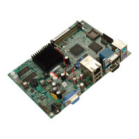
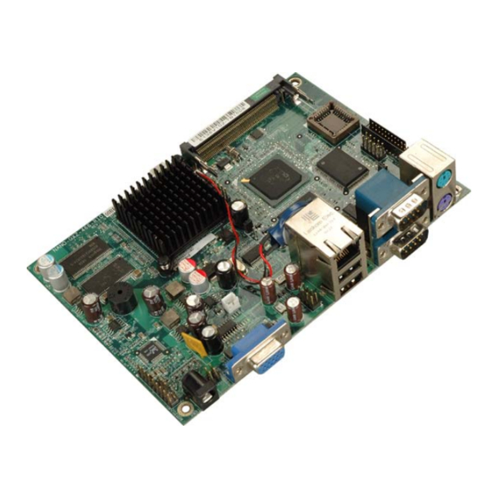
IEI Technology NANO-GX2 User Manual (172 pages)
EPIC SBC with AMD Geode GX 466 CPU with onboard RAM, CompactFlash, Mini PCI, IDE, VGA, LAN, USB 2.0, and Audio
Brand:
IEI Technology
| Category:
Motherboard
| Size: 4.47 MB
Table of Contents
Table of Contents
7
Introduction
17
Cpu Board Overview
18
Applications
18
Benefits
18
Features
19
General Overview
20
Figure 1-2: Overview (Front Side)
20
CPU Board Connectors
21
Figure 1-3: Overview (Solder Side)
21
Technical Specifications
22
Figure 1-1: NANO-GX2
22
Table 1-1: Technical Specifications
23
Detailed Specifications
25
Overview
26
Dimensions
26
Board Dimensions
26
External Interface Panel Dimensions
26
Figure 2-1: NANO-GX2 Dimensions (MM)
26
Figure 2-2: External Interface Panel Dimensions (MM)
27
Data Flow
28
Figure 2-3: Data Flow Block Diagram
28
Embedded AMD Geode™ GX 466 CPU
29
Figure 2-4: AMD Geode GX
29
Graphics Support
30
Figure 2-5: Graphics Support
30
Memory Support
31
Table 2-1: Geode™ GX Graphics Processor Features
31
Geodelink™ PCI Bridge
32
Geodelink
32
Figure 2-6: Onboard DDR RAM
32
Figure 2-7: Geodelink
32
10/100 Mb/S Ethernet
33
Figure 2-8: 10/100 Mb/S Ethernet
33
Mini PCI Expansion Slot
34
Figure 2-9: Mini PCI Slot
34
AMD Geode™ CS5536 System Chipset
35
Figure 2-10: System Chipset
35
Geodelink™ Interface Unit
36
Controller
37
Figure 2-11: IDE Interface
37
AC'97 Controller
38
Figure 2-12: Onboard Audio
38
Table 2-2: Supported HDD Specifications
38
Flash Interface
40
Figure 2-13: Compactflash® Slot
40
USB Controller
41
Figure 2-14: USB Ports
41
Serial Communications
42
Real Time Clock
42
Figure 2-15: Serial Communications
42
Bios
43
Environmental and Power Specifications
43
System Monitoring
43
Operating Temperature and Temperature Control
43
Figure 2-16: BIOS
43
Power Consumption
44
Table 2-3: Power Consumption
44
Unpacking
45
Anti-Static Precautions
46
Unpacking
46
Unpacking Precautions
46
Unpacking Checklist
47
Package Contents
47
Table 3-1: Package List Contents
48
Pinouts
49
Peripheral Interface Connectors
50
NANO-GX2 Layout
50
Figure 4-1: Connector and Jumper Locations
50
Peripheral Interface Connectors
51
Figure 4-2: Connector and Jumper Locations (Solder Side)
51
External Interface Panel Connectors
52
Internal Peripheral Connectors
52
Audio Connector
52
Table 4-1: Peripheral Interface Connectors
52
Table 4-2: Rear Panel Connectors
52
CD in Connector
53
Figure 4-3: Audio Connector Location
53
Table 4-3: Audio Connector Pinouts
53
Compactflash ® Socket
54
Figure 4-4: Audio CD in Connector Location
54
Table 4-4: Audio CD in Connector Pinouts
54
Figure 4-5: CF Card Socket Location
55
Digital I/O Connector
56
Table 4-5: CF Card Socket Pinouts
56
Fan Connector
57
Figure 4-6: Digital I/O Connector Locations
57
Table 4-6: Digital I/O Connector Pinouts
57
IDE Connector
58
Figure 4-7: Fan Connector Location
58
Table 4-7: Fan Connector Pinouts
58
Figure 4-8: IDE Connector Location
59
Mini PCI Slot
60
Table 4-8: IDE Connector Pinouts
60
Figure 4-9: Mini PCI Slot Location
61
Power and HDD LED Connector
64
Figure 4-10: Power and HDD LED Connector Location
64
Table 4-9: Mini PCI Slot Pinouts
64
Power Button Connector
65
Figure 4-11: Power Button Connector Location
65
Table 4-10: Power and HDD LED Connector Pinouts
65
Table 4-11: Power Button Connector Pinouts
65
Reset Button Connector
66
USB Connectors
66
Figure 4-12: Reset Button Connector Locations
66
Table 4-12: Reset Button Connector Pinouts
66
External Interface Connectors
67
Figure 4-13: USB Connector Pinout Locations
67
Table 4-13: USB Port Connector Pinouts
67
Ethernet Connector
68
Figure 4-14: NANO-GX2 On-Board External Interface Connectors
68
Table 4-14: Ethernet Connector Pinouts
68
Keyboard and Mouse Connector
69
Figure 4-15: Ethernet Connector
69
Table 4-15: Connector Leds
69
Power Input Connector
70
Figure 4-16: PS/2 Connector
70
Table 4-16: PS/2 Connectors
70
Serial Port Connectors
71
Table 4-17: Power Input Connector Pinouts
71
Table 4-18: Serial Port Pinouts
71
RS-232 Serial Port Connectors
71
USB Ports
72
VGA Connector
72
Figure 4-17: Serial Port Pinout Locations
72
Table 4-19: USB Connector Pinouts
72
Figure 4-18: VGA1 Connector
73
Table 4-20: VGA1 Connector Pinouts
73
Installation
75
Anti-Static Precautions
76
Installation Considerations
77
Installation Notices
77
Installation Checklist
78
CF Card Installation
79
Jumper Settings
80
Figure 5-1: CF Card Installation
80
AT/ATX Power Mode
81
Figure 5-2: Power Mode Jumper Pinout Location
81
Table 5-1: Jumpers
81
Table 5-2: Power Mode Jumper Settings
81
Board ID
82
Compactflash ® Master/Slave
82
Compactflash® Master/Slave
82
Figure 5-3: Board ID Jumper Pinout Location
82
Table 5-3: Board ID Jumper Settings
82
Chassis Installation
83
Airflow
83
Figure 5-4: Compactflash® Master/Slave Jumper Pinout Location
83
Table 5-4: Compactflash® Master/Slave Jumper Settings
83
NANO-GX2 Installation
84
Internal Peripheral Device Connections
84
ATA Flat Cable Connection
84
Table 5-5: IEI Provided Cables
84
USB Cable
85
Figure 5-5: IDE Cable Connection
85
Audio Kit Installation
86
Figure 5-6: Dual USB Cable Connection
86
External Peripheral Interface Connection
87
Figure 5-7: Audio Kit Connection
87
Keyboard and Mouse
88
Lan
89
Figure 5-8: PS/2 Keyboard/Mouse Connector
89
Serial Device
90
Figure 5-9: LAN Connection
90
Usb
91
Figure 5-10: Serial Device Connector
91
VGA Monitor
92
Figure 5-11: USB Connector
92
Figure 5-12: VGA Connector
93
Bios Setup
95
Introduction
96
Starting Setup
96
Using Setup
96
Getting Help
97
Unable to Reboot after Configuration Changes
97
Main BIOS Menu
97
Standard Cmos Features
100
IDE Primary Master/Slave
102
Advanced Bios Features
105
Advanced Chipset Features
109
Integrated Peripherals
111
Power Management Setup
114
Pnp/Pci Configurations
116
Pc Health Status
120
Software Drivers
123
Available Software Drivers
124
Vga Driver
124
Figure 7-1: VGA Driver Start up Screen
125
Figure 7-2: Select the Installation Method
126
Figure 7-3: VGA Driver Installation
127
Figure 7-4: VGA Driver Installation
127
Audio Driver
128
Figure 7-5: Close the VGA Driver Installation Wizard
128
Figure 7-6: Audio Driver Start up Screen
129
Figure 7-7: Select the Installation Method
130
Figure 7-8: Audio Driver Installation
131
Lan Driver
132
Figure 7-9: Close the Audio Driver Installation Wizard
132
Figure 7-10: CD Main Menu
133
Figure 7-11: AMD LX/GX CD Driver Menu
134
Figure 7-12: Locate the Setup Program Icon
134
Figure 7-13: Preparing Setup Screen
135
Figure 7-14: Install Wizard Welcome Screen
135
Figure 7-15: Installing Screen
136
ABIOS Options
137
B Terminology
141
C Digital I/O Interface
145
Introduction
146
Dio Connector Pinouts
146
Assembly Language Samples
147
Enable the DIO Input Function
147
Enable the DIO Output Function
147
D Watchdog Timer
149
E Address Mapping
153
Io Address Map
154
St Mb Memory Address Map
155
Irq Mapping Table
155
Dma Channel Assignments
156
F Compatibility
157
Compatible Operating Systems
158
Compatible Processors
158
Compatible Memory Modules
158
G Hazardous Materials Disclosure
159
Hazardous Materials Disclosure Table for IPB Products Certified as Rohs Compliant under 2002/95/EC Without Mercury
160
HAC'97 Audio Codec
163
Introduction
164
Accessing the AC'97 CODEC
164
Driver Installation
164
Sound Effect Configuration
165
Accessing the Sound Effects Manager
165
Sound Effect Manager Configuration Options
166
Advertisement
Advertisement
Related Products
IEI Technology NANO-GM45A
IEI Technology NANO-GM45A2
IEI Technology NANO-GM45A2-R10
IEI Technology NANO-PV-D4252
IEI Technology NANO-PV-N4552
IEI Technology Nano-PV-N4551
IEI Technology NANO-9452
IEI Technology NANO-BT Series
IEI Technology NANO-HM551-R10
IEI Technology NANO-PV-D5251-R10
IEI Technology Categories
Motherboard
Touch Panel
Computer Hardware
Single board computers
Desktop
More IEI Technology Manuals
Login
Sign In
OR
Sign in with Facebook
Sign in with Google
Upload manual
Upload from disk
Upload from URL