Table of Contents
Advertisement
Quick Links
Download this manual
See also:
User Manual
Advertisement
Chapters
Table of Contents

Related Manuals for IEI Technology NANO-LX


Summary of Contents for IEI Technology NANO-LX
-
Page 1: User Manual
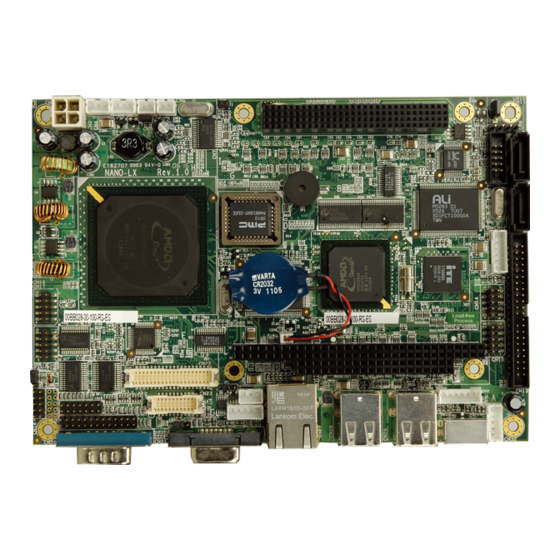
NANO-LX EPIC SBC NANO-LX EPIC SBC User Manual MODEL: NANO-LX EPIC AMD® Geode LX 800 SBC with VGA/LVDS/TFT Single GbE, SATA RAID, USB 2.0 and Audio User Manual Page I Rev. 1.23 – August 22, 2017... - Page 2 NANO-LX EPIC SBC Revision Date Version Changes August 22, 2017 1.22 Updated the following sections: Section 2.3: Data Flow Section 4.2.23: Serial Communications Connector Section 5.6.3: UART Port A RS-422/485 Select Jumper August 17, 2017 1.22 Clarified Section 4.2.23: Serial Communications...
- Page 3 NANO-LX EPIC SBC Copyright COPYRIGHT NOTICE The information in this document is subject to change without prior notice in order to improve reliability, design and function and does not represent a commitment on the part of the manufacturer. In no event will the manufacturer be liable for direct, indirect, special, incidental, or consequential damages arising out of the use or inability to use the product or documentation, even if advised of the possibility of such damages.
-
Page 4: Packing List
NANO-LX motherboard from or contact an IEI sales representative directly. To contact an IEI sales representative, please send an email to sales@ieiworld.com. The items listed below should all be included in the NANO-LX motherboard package. NANO-LX single board computer ... -
Page 5: Table Of Contents
1.1 NANO-LX CPU B ................2 OARD VERVIEW 1.1.1 NANO-LX CPU Board Applications..............2 1.1.2 NANO-LX CPU Board Benefits ................. 2 1.1.3 NANO-LX CPU Board Features ................ 3 1.2 NANO-LX SBC O ..................4 VERVIEW 1.2.1 NANO-LX CPU Board Connectors..............5 1.2.2 Technical Specifications.................. - Page 6 TEMS 4 CONNECTORS AND JUMPERS ................28 4.1 P ..............29 ERIPHERAL NTERFACE ONNECTORS 4.1.1 NANO-LX SBC Layout..................29 4.1.2 Peripheral Interface Connectors ..............30 4.1.3 Rear Panel Connectors ..................32 4.1.4 Onboard Jumpers..................... 32 4.2 I ..............33 NTERNAL...
- Page 7 NANO-LX EPIC SBC 4.2.12 Infrared Connector ..................45 4.2.13 Keyboard/Mouse Connector ................46 4.2.14 LED Power Connector................... 47 4.2.15 LVDS LCD Panel Connector ................. 48 4.2.16 Parallel Port Connector ................49 4.2.17 PC/104-Plus Connector ................. 50 4.2.18 Power Connector ................... 53 4.2.19 Power Input Connector..................
- Page 8 NANO-LX EPIC SBC 5.6.6 PC/104-Plus SERIRQ Select Jumper............... 77 5.6.7 LCD Panel (LVDS/TTL) Voltage select Jumper..........78 5.7 C .................... 78 HASSIS NSTALLATION 5.7.1 Airflow......................78 5.7.2 Motherboard Installation................. 79 5.8 I ............79 NTERNAL ERIPHERAL EVICE ONNECTIONS 5.8.1 Peripheral Device Cables ................79 5.8.2 ATA Flat Cable Connection ................
- Page 9 NANO-LX EPIC SBC 7 SOFTWARE DRIVERS .................... 128 7.1 A ................129 VAILABLE OFTWARE RIVERS ® 7.2 AMD VGA I ................... 131 NSTALLATION 7.3 A ................140 UDIO RIVER NSTALLATION 7.4 LAN D ......................147 RIVER 7.5 SATA/RAID D ..................... 151 RIVER 7.6 ISA D...
- Page 10 NANO-LX EPIC SBC List of Figures Figure 1-1: NANO-LX EPIC SBC....................2 Figure 1-2: NANO-LX CPU Board Overview (Front Side) ............4 Figure 1-3: NANO-LX CPU Board Overview (Solder Side) ............4 Figure 2-1: NANO-LX Dimensions (mm) ..................10 Figure 2-2: External Interface Panel Dimensions (mm) ............11 Figure 2-3: Data Flow Block Diagram ..................12...
- Page 11 NANO-LX EPIC SBC Figure 4-26 CN22 Connector Locations ..................61 Figure 4-27: NANO-LX CPU Board Rear Panel ................62 Figure 4-28: COM1 Pinout Locations..................62 Figure 4-29: CN24 Connector ......................63 Figure 4-30: CN27 Connector ......................64 Figure 4-31: CN31 Pinout locations ....................65 Figure 5-1: SO-DIMM Installation ....................71 Figure 5-2: CF Card Installation ....................72...
- Page 12 NANO-LX EPIC SBC Figure 7-13: Hardware Update Wizard Search Window............138 Figure 7-14: Windows Logo Testing Window ................. 138 Figure 7-15: Driver Installation Window .................. 139 Figure 7-16: Driver Installation Complete Window ..............139 Figure 7-17: Device Manager Window ..................140 Figure 7-18: Access Windows Control Panel .................
- Page 13 NANO-LX EPIC SBC List of Tables Table 1-1: Technical Specifications....................7 Table 1-2: Compatible Memory Modules..................8 Table 2-1: Geode LX Graphics Features ..................15 Table 2-2: Supported HDD Specifications..................16 Table 2-3: Power Consumption....................22 Table 3-1: Package List Contents ....................26 Table 3-2: Package List Contents ....................27 Table 4-1: Peripheral Interface Connectors ................31...
- Page 14 NANO-LX EPIC SBC Table 4-26: CN38 Connector Pinouts ..................58 Table 4-27: CN14, CN15, CN16, CN17 Connector Pinouts............59 Table 4-28: CN19 Connector Pinouts ..................59 Table 4-29: CN22 Connector Pinouts ..................60 Table 4-30: COM1 Pinouts ......................62 Table 4-31: CN24 Connector Pinouts ..................63 Table 4-32: CN27 Connector Pinouts ..................64...
- Page 15 NANO-LX EPIC SBC List of BIOS Menus BIOS Menu 1: AwardBIOS CMOS Setup Utility .................96 BIOS Menu 2: Standard CMOS Features..................98 BIOS Menu 3: IDE Primary Master ................... 100 BIOS Menu 4: Advanced BIOS Features ................. 103 BIOS Menu 5: Advanced Chipset Features................109 BIOS Menu 6: Flat Panel Configuration...................
-
Page 17: Introduction
NANO-LX EPIC SBC Chapter Introduction Page 1... -
Page 18: Nano-Lx Cpu Board Overview
The NANO-LX is particularly suitable for low power and fan-less applications. The NANO-LX supports a full range of functionality for an AT/ATX-compatible industrial computer in a space-saving 3.5” profile. The NANO-LX is equipped with an on board low-power consumption and high performance AMD® Geode™ LX800 processor. It also contains a DDR SO-DIMM socket that supports up to 1GB memory in size. -
Page 19: Nano-Lx Cpu Board Features
NANO-LX EPIC SBC 1.1.3 NANO-LX CPU Board Features Some of the NANO-LX SBC features are listed below: Complies with RoHS Supports AMD® Geode™ LX800 500 MHz CPU Supports up to 1GB of 400/333 MHz single channel DDR memory ... -
Page 20: Nano-Lx Sbc Overview
NANO-LX EPIC SBC 1.2 NANO-LX SBC Overview Figure 1-2: NANO-LX CPU Board Overview (Front Side) Figure 1-3: NANO-LX CPU Board Overview (Solder Side) Page 4... -
Page 21: Nano-Lx Cpu Board Connectors
1 x DIO connector 1 x CD_IN connector 1 x Keyboard/Mouse connector The NANO-LX SBC has the following connectors on the board rear panel: 1 x RS-232 connector 1 x VGA connector 1 x RJ-45 Ethernet connector ... -
Page 22: Technical Specifications
NANO-LX EPIC SBC 1.2.2 Technical Specifications NANO-LX SBC technical specifications are listed in Table 1-1. Detailed descriptions of each specification can be found in Chapter 2. SPECIFICATION CPUs Supported AMD® Geode™ LX800 Cache Memory 64K I/ 64k D L1 cache, 128K L2 cache System Chipset AMD®... -
Page 23: Compatible Operating Systems And Memory Modules
1.3 Compatible Operating Systems and Memory Modules The following sections list the operating systems (OS) and memory modules that have passed the test held by IEI. Please consider using these compatible OS and memory modules with the NANO-LX for the best performance. Page 7... -
Page 24: Operating System
NANO-LX EPIC SBC 1.3.1 Operating System The compatible operating systems include: DOS 6.22 Windows XP Windows 2000 QNX Neutrino 6.2.1 Fedora Core 3 RedHat 9.0 Mandrake Linux 2006 FreeBSD 5.2.1 1.3.2 Memory Module The following memory modules have been used while testing: Mfg. -
Page 25: Detailed Specifications
NANO-LX EPIC SBC Chapter Detailed Specifications Page 9... -
Page 26: Overview
NANO-LX EPIC SBC 2.1 Overview This chapter describes the specifications and on-board features of the NANO-LX in detail. 2.2 Dimensions 2.2.1 Board Dimensions The dimensions of the board are listed below: Length: 165.10mm Width: 115.00mm Figure 2-1: NANO-LX Dimensions (mm) -
Page 27: External Interface Panel Dimensions
Figure 2-2: External Interface Panel Dimensions (mm) 2.3 Data Flow The NANO-LX motherboard comes with an AMD® Geode™ LX800 CPU and an AMD® Geode™ CS5536 linked together by the GeodeLink™ Interface Unit. Figure 2-3 shows the data flow between the system chipset, the CPU and other components installed on the motherboard. -
Page 28: Cpu Support
NANO-LX EPIC SBC Figure 2-3: Data Flow Block Diagram 2.4 CPU Support The NANO-LX series motherboards all come with a preinstalled AMD® Geode™ LX800 500MHz CPU. ® 2.4.1 AMD Geode™ LX800 500MHz Overview The specifications for the 500MHz AMD® Geode™ LX800 are listed below... -
Page 29: Amd ® Geode™ Lx800 Memory Support
Geode™ LX800 Memory Support The AMD® Geode™ LX800 supports 64-bit DDR memory modules with frequencies up to 400MHz. The NANO-LX has one 200-pin DDR SO-DIMM SDRAM socket that supports one 64-bit 333 MHz or 400MHz DDR SO-DIMM memory module with a maximum capacity of 1GB. -
Page 30: Table 2-1: Geode Lx Graphics Features
NANO-LX EPIC SBC Command buffer interface Hardware accelerated rotation BLTs Color depth conversion Paletized color Full 8x8 color pattern buffer Separate base addresses for all channels Monochrome inversion Table 2-1: Geode LX Graphics Features lists a complete list of Geode LX graphics features. -
Page 31: Amd ® Geode™ Lx800 500Mhz Power Management
Lower power I/O Wakeup on SMI/INTR 2.5 System Chipset The NANO-LX series motherboards all have a preinstalled AMD® Geode™ CS5536 system chipset. The system chipset features are listed below. 82xx Legacy Devices System Management Bus (SMB) Controller ... -
Page 32: Amd ® Geode™ Cs5536 Ata-6 Controller
2.5.2 AMD Geode™ CS5536 ATA-6 Controller The single NANO-LX IDE connector supports two ATA-6 HDDs. An ATA-6 (Ultra ATA/100) compliant IDE controller on the AMD® Geode™ CS5536 has a maximum transfer rate of 100MB/s. ATA-6 includes advancements in error checking and ATA-6 drives are compatible with future interface additions. - Page 33 NANO-LX EPIC SBC 20-bit DAC and 18-bit ADC resolution 18-bit Stereo full-duplex CODEC with independent and variable sampling rate Complies with AC'97 2.3 specifications LINE/HP-OUT, MIC-IN and LINE-IN sensing 14.318MHz -> 24.576MHz PLL saves crystal 12.288MHz BITCLK input can be consumed...
-
Page 34: Amd ® Geode™ Cs5536 Flash Interface
2.5.5 AMD Geode™ CS5536 USB Controller Four external USB ports on the NANO-LX board are interfaced to the chipset USB controller. Four USB 1.1 or USB 2.0 devices can be connected simultaneously to the NANO-LX. The chipset USB controller has the following specifications: ... -
Page 35: Amd ® Geode™ Cs5536 Real Time Clock
RAM. 2.5.8 BIOS The BIOS flash memory chip on the NANO-LX has a licensed copy of AWARD BIOS loaded onto it. The BIOS flash memory chip is connected to the chipset via the LPC bus. The flash BIOS features are listed below: ... -
Page 36: 10/100M Ethernet
Ethernet controller is interfaced through first the PCI bus and then through the GeodeLink™ PCI Bridge to the CPU and system chipset. The Realtek RTL8100C controller provides 10Mbps or 100Mbps Ethernet connectivity to the NANO-LX. Some of the features of the Realtek RTL8100C are listed below. -
Page 37: Pci To Isa Bridge
NANO-LX EPIC SBC 2.6.3 PCI to ISA Bridge An ITE IT8888G PCI to ISA bridge single function device connects the onboard NANO-LX ISA bus PC/104 connector to the GeodeLink™ PCI bridge. The IT8888G has a PCI specification v2.1 compliant 32-bit PCI bus interface and supports both PCI Bus master and slave. -
Page 38: Operating Temperature And Temperature Control
Northbridge and Southbridge chipsets to ensure the operating temperature of these chips remain low. 2.7.3 Power Consumption Table 2-3 shows the power consumption parameters for the NANO-LX when an AMD® Geode LX800 processor is running with one 256MB DDR 400MHz memory module. -
Page 39: Unpacking
NANO-LX EPIC SBC Chapter Unpacking Page 23... -
Page 40: Anti-Static Precautions
Follow the anti-static precautions outlined in Section 3.1. Make sure the packing box is facing upwards so the NANO-LX does not fall out of the box. Make sure all the components shown in Section 3.3 are present. -
Page 41: Unpacking Checklist
If some of the components listed in the checklist below are missing, please do not proceed with the installation. Contact the IEI reseller or vendor you purchased the NANO-LX from or contact an IEI sales representative directly. To contact an IEI sales representative, please send an email to sales@ieiworld.com. -
Page 42: Table 3-1: Package List Contents
NANO-LX EPIC SBC SATA cables SATA power cable Mini jumper Pack Quick Installation Guide Utility CD Table 3-1: Package List Contents Page 26... -
Page 43: Optional Items
NANO-LX EPIC SBC 3.4 Optional Items ATX power cable (P/N: 32102-022100-100-RS) LPT cable (P/N: 32200-015100-RS) RS-232 and RS-422/485 cable (P/N: 19800-004300-100-RS) NANO-LX-CE050 Windows CE 5.0 & BSP, Software CD, Licensed sticker NANO-LX-XPE Windows XP Embedded & SLD, software CD, Licensed sticker... -
Page 44: Connectors And Jumpers
NANO-LX EPIC SBC Chapter Connectors and Jumpers Page 28... -
Page 45: Peripheral Interface Connectors
The locations of the peripheral interface connectors are shown in Section 4.1.1. A complete list of all the peripheral interface connectors can be seen in Section 4.1.2. 4.1.1 NANO-LX SBC Layout Figure 4-1 shows the onboard peripheral connectors, backplane peripheral connectors and onboard jumpers on the front side of the card. -
Page 46: Peripheral Interface Connectors
Figure 4-2 shows the onboard peripheral connectors on the solder side of the board. Figure 4-2: Connector and Jumper Locations (Solder Side) 4.1.2 Peripheral Interface Connectors Table 4-1 shows a list of the peripheral interface connectors on the NANO-LX SBC. Detailed descriptions of these connectors can be found in Section 4.2. Connector... -
Page 47: Table 4-1: Peripheral Interface Connectors
NANO-LX EPIC SBC Connector Type Label FDD connector 26-pin header CN34 IDE Interface connector 44-pin box header CN13 Inverter connector 5-pin wafer CN26 Infrared connector 5-pin wafer CN32 Keyboard/Mouse connector 6-pin wafer CN30 LED Power connector 6-pin wafer CN12 LVDS LCD Panel connector... -
Page 48: Rear Panel Connectors
NANO-LX EPIC SBC 4.1.3 Rear Panel Connectors Table 4-2 lists the rear panel connectors on the NANO-LX SBC. Detailed descriptions of these connectors can be found in Section 4.3. Connector Type Label Serial connector (COM1) RS-232 connector CN21 VGA Connector... -
Page 49: Internal Peripheral Connectors
4.2 Internal Peripheral Connectors Internal peripheral connectors on the SBC are only accessible when the SBC is outside of the chassis. This section has complete descriptions of all the internal, peripheral connectors on the NANO-LX SBC. 4.2.1 ATX Connector CN Label:... -
Page 50: Atx Power Button
NANO-LX EPIC SBC 4.2.2 ATX Power Button CN Label: CN Type: 2-pin wafer CN Pinouts: See Table 3-6 CN Location: See Figure 3-5 The ATX Power Button connector connects to the system power On/Off switch. DESCRIPTION DESCRIPTION ATX Power button +... -
Page 51: Audio Connector
NANO-LX EPIC SBC The Audio CD-In connector connects to audio sources such as CD/DVD-ROM optical drives. DESCRIPTION CD Left CD Right Table 4-6: CN8 Connector Pinouts Figure 4-5: CN8 Connector Location 4.2.4 Audio Connector CN Label: CN Type: 10-pin box header (2x5 pins) -
Page 52: Battery Connector
NANO-LX EPIC SBC LINE_OUT_L LINE_IN_L MIC1-IN MIC2-IN Table 4-7: CN9 Connector Pinouts Figure 4-6: CN9 Connector Location 4.2.5 Battery Connector CN Label: CN Type: 2-pin wafer CN Pinouts: See Table 4-8 CN Location: See Figure 4-7 This battery connector connects to an externally mounted 3V, Lithium, cell coin battery (VARTA CR2032). -
Page 53: Compactflash® Connector
NANO-LX EPIC SBC WARNING! 1. Keep batteries away from children. 2. There is a danger of explosion if the battery is incorrectly replaced. 3. Only a certified module from IEI can be used as a replacement. 4. Do not expose the battery to excessive heat or fire. -
Page 54: Table 4-9: Cn35 Connector Pinouts
NANO-LX EPIC SBC The Compact Flash connector is used to adapt Type II Compact Flash and CF+ cards for use in Type II (5 mm thick) PCMCIA card slots. DESCRIPTION DESCRIPTION -CD1 -CE1 -CE2 -VS1 -IORD -IOWR READY -VS2 RESET... -
Page 55: Figure 4-8: Cn35 Connector Location
NANO-LX EPIC SBC Figure 4-8: CN35 Connector Location Page 39... -
Page 56: Digital Input Output Connector
NANO-LX EPIC SBC 4.2.7 Digital Input Output Connector CN Label: CN18 CN Type: 10-pin header (2x5 pins) CN Pinouts: See Table 4-10 CN Location: See Figure 4-9 The Digital Input Output connector is a user-programmable general-purpose I/O controller managed through a Winbond W83697HF LPC SI/O chip. -
Page 57: Fdd Connector
NANO-LX EPIC SBC CN Location: See Figure 4-10 The Fan connector provides a 5Vcurrent to the cooling fan. The connector has a "rotation" pin to get rotation signals from the fan and notify the system so the system BIOS can recognize the fan speed. -
Page 58: Figure 4-11: Cn34 Connector Location
NANO-LX EPIC SBC DESCRIPTION DESCRIPTION STEP# INDEX# WDATA# DSA# WGATE# DSKCHG# TRACK0# MOTO0# RDATA# DIR# HEAD# Table 4-12 CN4 Connector Pinouts Figure 4-11: CN34 Connector Location Page 42... -
Page 59: Ide Interface Connector
NANO-LX EPIC SBC 4.2.10 IDE Interface Connector CN Label: CN13 CN Type: 44-pin box header (2x22 pins) CN Pinouts: See Table 4-13 CN Location: See Figure 4-12 The IDE Interface connector provides connectivity for two IDE devices. DESCRIPTION DESCRIPTION RESET#... -
Page 60: Inverter Connector
NANO-LX EPIC SBC Figure 4-12: CN13 Connector Location 4.2.11 Inverter Connector CN Label: CN26 CN Type: 5-pin wafer CN Pinouts: See Table 4-14 CN Location: See Figure 4-13 The Inverter connector connects to the LCD backlight. Page 44... -
Page 61: Infrared Connector
NANO-LX EPIC SBC DESCRIPTION BL_ADJ (default:GND) +12V BL_EN Table 4-14: CN26 Connector Pinouts Figure 4-13: CN26 Connector Location 4.2.12 Infrared Connector CN Label: CN32 CN Type: 5-pin wafer CN Pinouts: See Table 4-15 CN Location: See Figure 4-14 The integrated infrared connector supports both the SIR and ASKIR infrared protocols. -
Page 62: Keyboard/Mouse Connector
NANO-LX EPIC SBC DESCRIPTION IR-TX Table 4-15: CN32 Connector Pinouts Figure 4-14: CN32 Connector Location 4.2.13 Keyboard/Mouse Connector CN Label: CN30 CN Type: 6-pin wafer CN Pinouts: See Table 4-16 CN Location: See Figure 4-15 For alternative applications, an on board keyboard/mouse pin header connector is also available. -
Page 63: Led Power Connector
NANO-LX EPIC SBC Figure 4-15: CN30 Connector Location 4.2.14 LED Power Connector CN Label: CN12 CN Type: 6-pin wafer CN Pinouts: See Table 4-17 CN Location: See Figure 4-16 The LED power connector provides the connectivity to the power and hard drive activity LEDs on the chassis front panel. -
Page 64: Lvds Lcd Panel Connector
NANO-LX EPIC SBC Figure 4-16: CN12 Connector Location 4.2.15 LVDS LCD Panel Connector CN Label: CN23 CN Type: 20-pin crimp (2x10) CN Pinouts: See Table 4-18 CN Location: See Figure 4-17 The LVDS LCD connector connects to one channel (18-bit) LVDS panel. -
Page 65: Parallel Port Connector
CN Location: See Figure 4-18 The parallel port connector connects to a printer. The NANO-LX comes with a multi-mode (ECP/EPP/SPP) parallel port. The CN20 parallel port interface features a 26-pin flat-cable connector that requires an adapter cable if a traditional DB-25 connector is preferred. The parallel interface can be re-assigned to LPT2 or LPT3 through the BIOS configuration utility. -
Page 66: Pc/104-Plus Connector
NANO-LX EPIC SBC DESCRIPTION DESCRIPTION STROBE# AUTO FORM FEED# DATA0 ERROR# DATA1 INITIALIZE DATA2 PRINTER SELECT LN# DATA3 GROUND DATA4 GROUND DATA5 GROUND DATA6 GROUND DATA7 GROUND ACK- GROUND BUSY GROUND PAPER EMPTY GROUND PRINTER SELECT Table 4-19: CN20 Connector Pinouts Figure 4-18: CN20 Connector Location 4.2.17 PC/104-Plus Connector... - Page 67 NANO-LX EPIC SBC CN Location: See Figure 4-19 Use the PC/104-Plus connector to add auxiliary boards using stack-through connectors. Row A Row B Row C Row D IOCHCHK* SBHE* MEMCS16* RESETDRV LA23 IOCS16* LA22 IRQ10 IRQ9 LA21 IRQ11 LA20 IRQ12...
-
Page 68: Table 4-20: Cn7 (Pc/104) Connector Pinouts
NANO-LX EPIC SBC Row A Row B Row C Row D Table 4-20: CN7 (PC/104) Connector Pinouts GROUND TBD1 CBE0- AD11 AD10 N66EV AD14 AD13 AD12 +3.3V CBE1- AD15 +3.3V SERR- SBO- PERR- +3.3V SDONE STOP- +3.3V LOCK- +3.3V TRDY-... -
Page 69: Power Connector
NANO-LX EPIC SBC +12V INTA- INTB- INTC- -12v TBD2 GND/3.3V Table 4-21: CN7 (PCI-104) Connector Pinouts Figure 4-19: CN7 Connector Location 4.2.18 Power Connector CN Label: CN Type: 4-pin Molex power connector (2x2 pins) CN Pinouts: See Table 4-22 CN Location: See Figure 4-20 This connector supports the ATX-12V power supply. -
Page 70: Power Input Connector
NANO-LX EPIC SBC Figure 4-20: CN2 Connector Location 4.2.19 Power Input Connector CN Label: CN25 CN Type: 3-pin wafer CN Pinouts: See Table 4-23 CN Location: See Figure 4-21 The Power Input connector is a –5V/-12V power connector for ISA devices. -
Page 71: Reset Button Connector
NANO-LX EPIC SBC Figure 4-21: CN25 Connector Location 4.2.20 Reset Button Connector CN Label: CN Type: 2-pin wafer CN Pinouts: See Table 4-24 CN Location: See Figure 4-22 The Reset Button connector connects to an external reset button through an adapter cable. -
Page 72: Sata Drive Ports
NANO-LX EPIC SBC Figure 4-22: CN6 Connector Location 4.2.21 SATA Drive Ports CN Label: CN36, CN37 CN Type: 7-pin port CN Pinouts: See Table 4-25 CN Location: See Figure 4-23 The SATA drive ports provide connectivity to SATA drives with a maximum data transfer rate of 150MB/s. -
Page 73: Sata Power Connector
NANO-LX EPIC SBC CAUTION! SATA hard drives may come with both a 4P power connector and a SATA power interface. Attach either the 4P connector or the SATA power cable to the SATA DO NOT hard drives. attach both the power connectors to your SATA hard drives at the same time! Doing so will cause damage. -
Page 74: Serial Communications Connector
CN14, CN15, CN16, CN17, CN19 CN Type: 14-pin headers (2x5 pins) CN Pinouts: See Table 3-27 and Table 4-28 CN Location: See Figure 4-25 The NANO-LX offers four ten-pin headers and one 14-pin header for serial connections. DESCRIPTION DESCRIPTION Page 58... -
Page 75: Tft Ttl Lcd Connector
NANO-LX EPIC SBC Table 4-27: CN14, CN15, CN16, CN17 Connector Pinouts DESCRIPTION DESCRIPTION COM2 UART TXD485+ TXD485# Port A RXD485+ RXD485# Table 4-28: CN19 Connector Pinouts Figure 4-25 CN14, CN15, CN16, CN17, CN19 Connector Locations 4.2.24 TFT TTL LCD Connector... -
Page 76: Table 4-29: Cn22 Connector Pinouts
NANO-LX EPIC SBC CN Location: See Figure 4-26 TFT LCD (24-bit one channel; DF13-40DP-1.25V) DESCRIPTION DESCRIPTION LCD_VCC LCD_VCC GROUND GROUND LCD_VCC LCD_VCC GROUND I_SDA GROUND GROUND VSYNC HSYNC LCD_EN DISP_EN Table 4-29: CN22 Connector Pinouts NOTE: The supplied voltage (3.3V and 5V) can be selected via JP7. -
Page 77: External (Rear Panel) Connectors
Figure 4-26 CN22 Connector Locations 4.3 External (Rear Panel) Connectors Figure 4-27 shows the NANO-LX CPU board rear panel. The peripheral connectors on the back panel can connect to external devices when the SBC is installed in a chassis. The peripheral connectors on the rear panel are: ... -
Page 78: Serial Connector (Com1)
1 x VGA connector 1 x RJ-45 Ethernet connector 2 x USB combo connectors 1 x PS/2 connector Figure 4-27: NANO-LX CPU Board Rear Panel 4.3.1 RS-232 Serial Connector (COM1) CN Label: CN21 CN Type: RS-232 CN Pinouts:... -
Page 79: Vga Connector
NANO-LX EPIC SBC 4.3.2 VGA Connector CN Label: CN24 CN Type: HD-D-sub 15 Connector CN Pinouts: See Table 4-31 and Figure 4-29 CN Location: See Figure 4-27 The standard 15-pin VGA connector connects to a CRT or LCD monitor. DESCRIPTION... -
Page 80: Usb Combo Connectors
NANO-LX EPIC SBC DESCRIPTION DESCRIPTION MDIA3- MDIA1+ MDIA3+ MDIA2+- MDIA2- MDIA0- MDIA1- MDIA0+ Table 4-32: CN27 Connector Pinouts Figure 4-30: CN27 Connector The RJ-45 Ethernet connector has two status LEDs, one green and one yellow. The green LED indicates activity on the port and the yellow LED indicates the port is linked (Table 4-33). -
Page 81: Keyboard/Mouse Connector
NANO-LX EPIC SBC DESCRIPTION DESCRIPTION VCC (+5V) VCC (+5V) DATA- DATA- DATA+ DATA+ Table 4-34: CN28, CN29 Connector Pinouts 4.3.5 Keyboard/Mouse Connector CN Label: CN31 CN Type: PS/2 CN Pinouts: See Table 4-35 and Figure 4-31 CN Location: See Figure 4-27 The Keyboard/Mouse connector connects to a mouse and keyboard. -
Page 82: Installation And Configuration
NANO-LX EPIC SBC Chapter Installation and Configuration Page 66... -
Page 83: Anti-Static Precautions
Electrostatic discharge (ESD) can cause serious damage to electronic components, including the NANO-LX. Dry climates are especially susceptible to ESD. It is therefore critical that whenever the NANO-LX, or any other electrical component is handled, the following anti-static precautions are strictly adhered to. -
Page 84: Installation Considerations
NANO-LX is installed. All installation notices pertaining to the installation of the NANO-LX should be strictly adhered to. Failing to adhere to these precautions may lead to severe damage of the NANO-LX and injury to the person installing the motherboard. 5.2.1 Installation Notices... -
Page 85: Installation Checklist
Allow screws to come in contact with the PCB circuit, connector pins, or its components. 5.2.2 Installation Checklist The following checklist is provided to ensure the NANO-LX is properly installed. All the items in the packing list are present ... -
Page 86: Unpacking
Follow the anti-static precautions outlined in Section 5.1. Make sure the packing box is facing upwards so the NANO-LX does not fall out of the box. Make sure all the components in the checklist shown in Section 5.3.2 are present. -
Page 87: So-Dimm Installation
Figure 5-1. Figure 5-1: SO-DIMM Installation Step 1: Locate the SO-DIMM socket. Place the NANO-LX on an anti-static pad with the solder side facing up. Step 2: Align the SO-DIMM with the socket. The SO-DIMM must be oriented in such a way that the notch in the middle of the SO-DIMM must be aligned with the plastic bridge in the socket. -
Page 88: Cf Card Installation
The NANO-LX supports CF Type II card. For the complete specifications of the supported CF cards please refer to Chapter 2. To install the a CF Type II card onto the NANO-LX, please follow the steps below: Step 1: Locate the CF card socket. Place the NANO-LX on an anti-static pad with the solder side facing up. -
Page 89: Jumper Settings
OPEN a jumper means removing the Figure 5-3: Jumper Locations plastic clip from a jumper. Before the NANO-LX is installed in the system, the jumpers must be set in accordance with the desired configuration. The jumpers on the NANO-LX are listed in Table 5-1. Description... -
Page 90: Lcd Panel Shift Clock Jumper
NANO-LX EPIC SBC system fails to boot due to improper BIOS settings, reset the CMOS contents by disconnecting and reconnecting the BT1 battery connector. Use small-sized needle nose pliers to carefully disconnect and reconnect the BT1 battery connector. Figure 5-4: Jumper Locations 5.6.1 LCD Panel Shift Clock Jumper... -
Page 91: Com1/2 Port Ri And Voltage Selection Jumper (Optional)
NANO-LX EPIC SBC Description LVDS Clock Normal Output (Default) LVDS Clock Invert Output Table 5-2: JP1 Jumper Settings 5.6.2 COM1/2 Port RI and Voltage Selection Jumper (Optional) Jumper Label: Jumper Type: 10-pin header (2x5 pins) Jumper Settings: See Table 5-3... -
Page 92: At/Atx Power Mode Select Jumper
NANO-LX EPIC SBC Description UART RxD Signal connect to RS-422 (Default) UART RxD Signal connect to RS-485 Table 5-4: JP3 Jumper Settings 5.6.4 AT/ATX Power Mode Select Jumper Jumper Label: Jumper Type: 2-pin header Jumper Settings: See Table 5-5 Jumper Location: See Figure 5-4 The JP4 jumper block controls the connection to a power supply. -
Page 93: Pc/104-Plus Vio Voltage Select Jumper
NANO-LX EPIC SBC 5.6.5 PC/104-Plus VIO Voltage Select Jumper Jumper Label: Jumper Type: 3-pin header Jumper Settings: See Table 5-6 Jumper Location: See Figure 5-4 The JP5 jumper sets the voltage to the PC/104-Plus connector. Description PC104 Plus VIO output voltage select 5V PC104 Plus VIO output voltage select 3.3V (Default) -
Page 94: Lcd Panel (Lvds/Ttl) Voltage Select Jumper
WARNING: Airflow is critical to the cooling of the CPU and other onboard components. The chassis in which the NANO-LX must have air vents to allow cool air to move into the system and hot air to move out. Page 78... -
Page 95: Motherboard Installation
NANO-LX EPIC SBC The NANO-LX must be installed in a chassis with ventilation holes on the sides allowing airflow to travel through the heat sink surface. In a system with an individual power supply unit, the cooling fan of a power supply can also help generate airflow through the board surface. -
Page 96: Ata Flat Cable Connection
NANO-LX EPIC SBC 5.8.2 ATA Flat Cable Connection The ATA 66/100 flat cable connects to the NANO-LX to one or two IDE devices. To connect an IDE HDD to the NANO-LX please follow the instructions below. Step 1: Locate the IDE connector. The location/s of the IDE device connector/s is/are shown in Chapter 3. -
Page 97: At Power Connection
NANO-LX EPIC SBC 5.8.3 AT Power Connection Follow the instructions below to connect the NANO-LX to an AT power supply. WARNING: Disconnect the power supply power cord from its AC power source to prevent a sudden power surge to the NANO-LX. -
Page 98: Audio Kit Installation
Figure 5-7: Connect Power Cable to Power Supply 5.8.4 Audio Kit Installation The Audio Kit that came with the NANO-LX connects to the audio connector on the NANO-LX. The audio kit consists of three audio jacks. Mic-in connects to a microphone. -
Page 99: Parallel Port Cable
NANO-LX EPIC SBC Figure 5-8: Audio Kit Cable Connection Step 3: Connect the audio devices. Connect speakers to the line-out audio jack. Connect the output of an audio device to the line-in audio jack. Connect a microphone to the mic-in audio jack.Step 0:... -
Page 100: Single Rs-232 Cable
NANO-LX EPIC SBC Figure 5-9: LPT Cable Connection Step 4: Attach the LPT connector to the chassis. To secure the LPT interface connector to the chassis please refer to the installation instructions that came with the chassis. Step 5: Connect LPT device. Once the LPT interface connector is connected to the chassis, the LPT device can be connected to the LPT interface connector. -
Page 101: Sata Drive Connection
Figure 5-11: Single RS-232 Cable Installation 5.8.7 SATA Drive Connection The NANO-LX is shipped with two SATA drive cables and one SATA drive power cable. To connect the SATA drives to the connectors, please follow the steps below. Step 3: Locate the connectors. -
Page 102: Figure 5-12: Sata Drive Cable Connection
NANO-LX EPIC SBC Figure 5-12: SATA Drive Cable Connection Step 5: Connect the cable to the SATA disk. Connect the connector on the other end of the cable to the connector at the back of the SATA drive. See Figure 5-13. -
Page 103: External Peripheral Interface Connection
Serial port devices USB devices VGA monitors To install these devices, connect the corresponding cable connector from the actual device to the corresponding NANO-LX external peripheral interface connector making sure the pins are properly aligned. Page 87... -
Page 104: Lan Connection (Single Connector)
Step 0: 5.9.2 PS/2 Keyboard/Mouse Connection The NANO-LX has a single PS/2 connector on the external peripheral interface panel. The PS/2 connector is connected to a keyboard/mouse through the keyboard/mouse Y cable. To connect a keyboard/mouse to the NANO-LX, please follow the instructions below. -
Page 105: Figure 5-15: Ps/2 Connector
Once the connector is properly aligned, insert the PS/2 connector from the keyboard/mouse Y cable into the PS/2 connector on the NANO-LX. See Figure 5-15. Step 4: Connect the keyboard and mouse. A keyboard and mouse can each be connected to one of the PS/2 connectors. -
Page 106: Serial Device Connection
Step 0: 5.9.4 USB Connection (Dual Connector) The external USB Series "A" receptacle connectors provide easier and quicker access to external USB devices. Follow the steps below to connect USB devices to the NANO-LX. Page 90... -
Page 107: Vga Monitor Connection
Figure 5-17: USB Connector 5.9.5 VGA Monitor Connection The NANO-LX has a single female DB-15 connector on the external peripheral interface panel. The DB-15 connector is connected to a CRT or VGA monitor. To connect a monitor to the NANO-LX, please follow the instructions below. -
Page 108: Figure 5-18: Vga Connector
Once the connectors are properly aligned with the insert the male connector from the VGA screen into the female connector on the NANO-LX. See Figure 5-18. Figure 5-18: VGA Connector Step 4: Secure the connector. Secure the DB-15 VGA connector from the VGA monitor to the external interface by tightening the two retention screws on either side of the connector. -
Page 109: Award Bios Setup
NANO-LX EPIC SBC Chapter Award BIOS Setup Page 93... -
Page 110: Introduction
NANO-LX EPIC SBC 6.1 Introduction A licensed copy of Phoenix Award BIOS is preprogrammed into the ROM BIOS. The BIOS setup program allows users to modify the basic system configuration. This chapter describes how to access the BIOS setup program and the configuration options that may be changed. -
Page 111: Getting Help
NANO-LX EPIC SBC Function Item help Previous values for the page menu items Fail-safe defaults for the current page menu items Optimized defaults for the current page menu items Menu in BIOS Save changes and Exit BIOS Table 6-1: BIOS Navigation Keys 6.1.3 Getting Help... -
Page 112: Bios Menu 1: Awardbios Cmos Setup Utility
NANO-LX EPIC SBC BIOS Menu 1: AwardBIOS CMOS Setup Utility NOTE: The following sections will completely describe the menus listed below and the configuration options available to users. The following menu options are seen in BIOS Menu 1. Standard CMOS Features: Changes the basic system configuration. -
Page 113: Load Fail-Safe Defaults
NANO-LX EPIC SBC Load Fail-Safe Defaults Select this option to load failsafe default values for each BIOS parameter in the setup menus. Press F6 for this operation on any page. Load Optimized Defaults Select this option to load optimal default values for each BIOS parameter in the setup menus. -
Page 114: Standard Cmos Features
NANO-LX EPIC SBC 6.2 Standard CMOS Features Use the Standard CMOS Features BIOS menu (BIOS Menu 2) to set basic BIOS configuration options. BIOS Menu 2: Standard CMOS Features Date [Day mm:dd:yyyy] The Date option sets the system date. -
Page 115: Drive A [1.44M, 3.5In]
NANO-LX EPIC SBC IDE device configurations are changed or set in the IDE Configuration menu (BIOS Menu 3). If an IDE device is detected, and one of the above listed two BIOS configuration options is selected, the IDE configuration options shown in Section 6.2.1 appear. -
Page 116: Ide Primary Master/Slave
NANO-LX EPIC SBC Base Memory: The Base Memory is NOT user configurable. The POST determines the amount of base (or conventional) memory installed in the system. The value of the base memory is typically 512K for systems with 512K memory installed, or 640K for systems with 640K or more memory installed. -
Page 117: Ide Hdd Auto-Detection [Press Enter]
NANO-LX EPIC SBC IDE HDD Auto-Detection [Press Enter] Use the IDE HDD Auto-Detection option to enable BIOS to automatically detect the IDE settings. Select IDE HDD Auto-Detection and press E . BIOS automatically detects NTER the HDD type. Do not set this option manually. -
Page 118: Capacity
NANO-LX EPIC SBC Select this mode if the HDD capacity is more than 8.4GB. This mode is an extended ECHS mode and while it Large supports HDDs larger than 504MB, recommended. (Default) If you are unsure of what access mode to set, select this Auto option. -
Page 119: Advanced Bios Features
NANO-LX EPIC SBC Sector The Sector specification indicates how many logical sectors the HDD has been divided into. 6.3 Advanced BIOS Features CPU and peripheral device configuration options are accessed in the Advanced BIOS Features menu (BIOS Menu 4). -
Page 120: Cpu Internal Cache [Disabled]
NANO-LX EPIC SBC are running such a program, it is recommended that the virus protection function be disabled beforehand. Use the Virus Warning option to enable BIOS to monitor the boot sector and partition table of the HDD for any attempted modification. If a modification attempt is made, the BIOS halts the system and an error message appears. -
Page 121: Boot Device
NANO-LX EPIC SBC Enabled Enables SATA IDE use in DOS mode. Boot Device Use the Boot Device options to select the order of the devices the system boots from. There are three boot device configuration options: First Boot Device [Default: HDD-0] ... -
Page 122: Boot Up Floppy Seek [Enabled]
NANO-LX EPIC SBC Enabled (Default) The system looks for second and third boot devices if the first one is not found. Boot Up Floppy Seek [Enabled] Use the Boot Up Floppy Seek option to enable the BIOS to determine if the floppy disk drive installed has 40 or 80 tracks during the POST. -
Page 123: Typematic Rate (Chars/Sec) [6]
NANO-LX EPIC SBC down, it begins to report that the key has been pressed repeatedly. This feature accelerates cursor movement with the arrow keys. Disabled (Default) Disables the typematic rate. Enabled Enables the typematic rate. Typematic Rate (Chars/sec) [6] The Typematic Rate option can only be configured if the Typematic Rate Setting is enabled. -
Page 124: Os Select For Dram > 64Mb [Non-Os2]
NANO-LX EPIC SBC Setup (Default) The system does not boot and access to Setup is denied if the correct password is not entered at the prompt. The system boots, but access to Setup is denied if the System correct password is not entered at the prompt. -
Page 125: Advanced Chipset Features
NANO-LX EPIC SBC 6.4 Advanced Chipset Features Use the Advanced Chipset Features menu (BIOS Menu 5) to change chipset configuration options. BIOS Menu 5: Advanced Chipset Features CPU Frequency [500MHz] Use the CPU Frequency option to set the CPU frequency. -
Page 126: Video Memory Size [8M]
NANO-LX EPIC SBC Video Memory Size [8M] Use the Video Memory Size option to determine how much memory is allocated to the video graphics device. The Video Memory Size options are: Disabled 8M (Default) ... -
Page 127: Onboard Ide [Enabled]
NANO-LX EPIC SBC Disabled The onboard USB controller is disabled. (Default) The onboard USB controller is detected and enabled. Enabled OnBoard IDE [Enabled] Use the OnBoard IDE option to enable or disable the onboard IDE. Disabled The onboard IDE is disabled. -
Page 128: Flat Panel Configuration
NANO-LX EPIC SBC 6.4.1 Flat Panel Configuration Use the Flat Panel Configuration menu (BIOS Menu 6) to set the configuration settings for the flat panel screen connected to the system. BIOS Menu 6: Flat Panel Configuration Flat Panel Type [TFT] Use the Flat Panel Type option to specify the type of flat panel screen connected to the system. -
Page 129: Hsync Polarity [Normal High]
NANO-LX EPIC SBC 320 x 240 640 x 480 800 x 600 (Default) 1024 x 768 1152 x 864 1280 x 1024 1600 x 1200 320 x 234 640 x 240 ... -
Page 130: Integrated Peripherals
NANO-LX EPIC SBC 6.5 Integrated Peripherals Use the Integrated Peripherals menu (BIOS Menu 7) to change the configuration options for the attached peripheral devices.. BIOS Menu 7: Integrated Peripherals Drive PIO Mode [Auto] Use the Drive PIO Mode options below to select the Programmed Input/Output (PIO) mode for the following HDDs: ... -
Page 131: Ide Udma [Auto]
NANO-LX EPIC SBC Mode 2 PIO mode 2 selected with a maximum transfer rate of 8.3MBps. PIO mode 3 selected with a maximum transfer rate of 11.1MBps. Mode 3 Mode 4 PIO mode 4 selected with a maximum transfer rate of 16.6MBps. -
Page 132: Onboard Fdc Controller [Enabled]
NANO-LX EPIC SBC Onboard FDC Controller [Enabled] Use the Onboard FDC Controller option to enable or disable the onboard floppy controller. If the system is not connected to a floppy disk or uses an adapter for the FDD, this option can be disabled. -
Page 133: Rxd, Txd Active [Hi,Lo]
NANO-LX EPIC SBC IrDA IrDA is set as the IR serial mode. If this option is selected, COM2 will be disabled. ASKIR is set as the IR serial mode. If this option is ASKIR selected, COM2 will be disabled. -
Page 134: Onboard Serial Port # [Xxx]
NANO-LX EPIC SBC IR-Rx2Tx2 (Default) Onboard Serial Port # [XXX] Use the Onboard Serial Port # option to select the I/O address and IRQ for any additional onboard serial ports. The Onboard Serial Port # address options are: ... -
Page 135: Epp Mode Select [Epp1.7]
NANO-LX EPIC SBC parallel port devices but is slow. The parallel port operates in the enhanced parallel port mode (EPP). The EPP mode supports bi-directional communication between the system and the parallel port device and the transmission rates between the two are much faster than the SPP mode. -
Page 136: Power Management Setup
NANO-LX EPIC SBC 6.6 Power Management Setup Use the Power Management Setup menu (BIOS Menu 8) to set the BIOS power management and saving features. BIOS Menu 8: Power Management Setup AC Power Mode [ATX] Use the AC Power Mode option to select the power mode. -
Page 137: Pnp/Pci Configurations
NANO-LX EPIC SBC down longer than four seconds otherwise the system enters a low power usage state. 6.7 PnP/PCI Configurations Use the PnP/PCI Configurations menu (BIOS Menu 9) to set the plug and play, and PCI options. BIOS Menu 9: PnP/PCI Configurations ... -
Page 138: Reset Configuration Data [Disabled]
NANO-LX EPIC SBC Reset Configuration Data [Disabled] Use the Reset Configuration Data option to reset the Extended System Configuration Data (ESCD) when exiting setup if booting problems occur after a new add-on is installed. (Default) ESCD will not be reconfigured Disabled ... -
Page 139: Bios Menu 10: Irq Resources
NANO-LX EPIC SBC BIOS Menu 10: IRQ Resources The IRQ Resources menu has the following options: IRQ-3 assigned to IRQ-4 assigned to IRQ-7 assigned to IRQ-10 assigned to IRQ-11 assigned to The above options all have the following default options. -
Page 140: Memory Resources [Press Enter]
NANO-LX EPIC SBC x Memory Resources [Press Enter] The Memory Resources menu (BIOS Menu 11) can only be accessed if the Resources Controlled By option is set to Manual. Use Memory Resources to select a base address and the length for the memory area used by a peripheral that requires high memory. -
Page 141: Reserved Memory Base [N/A]
NANO-LX EPIC SBC Reserved Memory Base [N/A] The Reserved Memory Base option specifies the base address for the peripheral device. The Reserved Memory Base options are: N/A (Default) C800 CC00 D000 D400 D800 ... -
Page 142: Pc Health Status
NANO-LX EPIC SBC 6.8 PC Health Status The PC Health Status menu (BIOS Menu 12) has no user configurable options, but shows system operating parameters that are essential to the stable operation of the system. BIOS Menu 12: PC Health Status The following system parameters are monitored by the PC Health Status menu. -
Page 143: Voltages
NANO-LX EPIC SBC Voltages The following voltages are monitored: Vcore VccMem +3.3 V +5 V +12 V VBAT(V) Page 127... -
Page 144: Software Drivers
NANO-LX EPIC SBC Chapter Software Drivers Page 128... -
Page 145: Available Software Drivers
Start button, select Run, then type X:\autorun.exe (replace X with the actual drive letter for your CD-ROM) to access the IEI Driver CD main menu. Step 1: From the AMD® LX/GX Driver CD main menu (Figure 7-1), click NANO-LX. Page 129... -
Page 146: Figure 7-1: Amd® Lx/Gx Cd Main Menu
NANO-LX EPIC SBC Figure 7-1: AMD® LX/GX CD Main Menu Step 2: A window appears listing the drivers available for installation (Figure 7-2). Figure 7-2: AMD® LX/GX CD Driver Menu Page 130... -
Page 147: Amd ® Vga Installation
Select any item from the list to view more information on the driver installation, or select Manual to navigate to the NANO-LX user manual. Step 0: The following sections fully describe the driver installation procedures for the NANO-LX SBC. ®... -
Page 148: Figure 7-4: Double Click The System Icon
NANO-LX EPIC SBC Figure 7-4: Double Click the System Icon Step 3: Click the Device Manager tab (Figure 7-5). Figure 7-5: Click the Device Manager Tab Page 132... -
Page 149: Figure 7-6: Device Manager List
NANO-LX EPIC SBC Step 4: A list of system hardware devices appears (Figure 7-6). Figure 7-6: Device Manager List Step 5: Double-click the Video Controller device. Step 6: The Video Controller Properties window appears (Figure 7-7). Page 133... -
Page 150: Figure 7-7: Video Controller Properties Window
NANO-LX EPIC SBC Figure 7-7: Video Controller Properties Window Step 7: Click the Update Driver button in the Driver tab. Step 8: The Hardware Update Wizard appears (Figure 7-8). Page 134... -
Page 151: Figure 7-8: Hardware Update Wizard
NANO-LX EPIC SBC Figure 7-8: Hardware Update Wizard Step 9: Select “No, not this time,” and click N to continue. Step 10: The following window (Figure 7-9) appears. Figure 7-9: Install Options Window Step 11: Select “Install from a list or specific location…” and click N to continue. -
Page 152: Figure 7-10: Search Options Window
NANO-LX EPIC SBC Figure 7-10: Search Options Window Step 13: Select “Search for the best driver in these locations,” “Include this location in the search,” and click B to continue. ROWSE Step 14: The following window (Figure 7-11) appears. Figure 7-11: Folder Selection Window... -
Page 153: Figure 7-12: Search Options Window
NANO-LX EPIC SBC Step 15: Select the proper driver folder under the “X:\VGA\LX 800\XP” directory in the location browsing window, where “X:\” is the system CD drive, and click O continue. Step 16: The following window (Figure 7-12) appears. Figure 7-12: Search Options Window... -
Page 154: Figure 7-13: Hardware Update Wizard Search Window
NANO-LX EPIC SBC Figure 7-13: Hardware Update Wizard Search Window Step 19: The following window (Figure 7-14) appears. Figure 7-14: Windows Logo Testing Window Step 20: Click C to continue. ONTINUE NYWAY Step 21: The following window (Figure 7-15) appears as the driver is installed. -
Page 155: Figure 7-15: Driver Installation Window
NANO-LX EPIC SBC Figure 7-15: Driver Installation Window Step 22: After the driver installation process is complete, a confirmation screen appears (Figure 7-16). Figure 7-16: Driver Installation Complete Window Step 23: Click F to exit the program. INISH Page 139... -
Page 156: Audio Driver Installation
NANO-LX EPIC SBC Step 24: The Device Manager Window now shows the installed AMD graphics driver (Figure 7-17). Step 0: Figure 7-17: Device Manager Window 7.3 Audio Driver Installation To install the audio driver please follow the steps below. Step 1: Open Windows Control Panel (Figure 7-18). -
Page 157: Figure 7-18: Access Windows Control Panel
NANO-LX EPIC SBC Figure 7-18: Access Windows Control Panel Step 2: Double click the System icon (Figure 7-19). Page 141... -
Page 158: Figure 7-19: Double Click The System Icon
NANO-LX EPIC SBC Figure 7-19: Double Click the System Icon Step 3: Double click the Device Manager tab (Figure 7-20). Figure 7-20: Double Click the Device Manager Tab Step 4: A list of system hardware devices appears (Figure 7-21). Page 142... -
Page 159: Figure 7-21: Device Manager List
NANO-LX EPIC SBC Figure 7-21: Device Manager List Step 5: Double click the listed device that has question marks next to it. (This means Windows does not recognize the device). The Device Driver Wizard appears (Figure 7-22). Click N to continue. -
Page 160: Figure 7-22: Search For Suitable Driver
NANO-LX EPIC SBC Figure 7-22: Search for Suitable Driver Step 7: Select “Specify a Location” in the Locate Driver Files window (Figure 7-23). Click N to continue. Page 144... -
Page 161: Figure 7-23: Locate Driver Files
NANO-LX EPIC SBC Figure 7-23: Locate Driver Files Step 8: Select “X:\ Audio\WDM_Audio_v2.03.00” directory in the location browsing window, where “X:\” is the system CD drive (Figure 7-24). Page 145... -
Page 162: Figure 7-24: Location Browsing Window
NANO-LX EPIC SBC Figure 7-24: Location Browsing Window Step 9: Click OK to continue. A driver files location menu window appears. Select the LXWDMAu.inf file and click O to continue. The driver is installed. Step 0: Page 146... -
Page 163: Lan Driver
NANO-LX EPIC SBC 7.4 LAN Driver To install the LAN driver, please follow the steps below. Step 1: Click LAN from the AMD LX/GX CD Driver Menu to open a window to the X:\LAN\Realtek (where X:\ is the system CD drive) folder on the driver CD. -
Page 164: Figure 7-27: Install Wizard Welcome Screen
NANO-LX EPIC SBC Figure 7-27: Install Wizard Welcome Screen Step 7: Click N to continue the installation or C to stop the installation. ANCEL Step 8: The Install Wizard starts to install the LAN driver. Step 9: Once the installation is complete, the InstallShield Wizard Complete screen appears (Figure 7-28). -
Page 165: Figure 7-28: Installing Screen
NANO-LX EPIC SBC Figure 7-28: Installing Screen Step 10: Click F to complete the installation and exit the Install Shield Wizard. INISH Step 11: Once the installation process is complete, the computer may be restarted immediately or later. Select the preferred option and click F... -
Page 166: Figure 7-29: Restart The Computer
NANO-LX EPIC SBC Figure 7-29: Restart the Computer Page 150... -
Page 167: Sata/Raid Driver
NANO-LX EPIC SBC 7.5 SATA/RAID Driver To install the SATA/RAID driver, please follow the steps below. Step 1: Click SATA from the AMD LX/GX CD Driver Menu to open a window to the X:\SATA\VIA VT6421 (where X:\ is the system CD drive) folder on the driver CD. -
Page 168: Figure 7-31: Install Wizard Welcome Screen
NANO-LX EPIC SBC Figure 7-31: Install Wizard Welcome Screen Step 5: Click N to continue the installation or C to stop the installation. ANCEL Step 6: Select the components to install. Click N to continue the installation (Figure 7-32). Figure 7-32: Components to Install... -
Page 169: Figure 7-33: Confirm The Installing Component List
NANO-LX EPIC SBC Step 7: Confirm the components to install by clicking N . (Figure 7-33) Figure 7-33: Confirm the Installing Component List Step 8: The Install Wizard starts to install the driver (Figure 7-34). Figure 7-34: Installing Screen Step 9: Once the installation is complete, the InstallShield Wizard Complete screen appears (Figure 7-35). -
Page 170: Figure 7-35: Installshield Wizard Complete Screen
NANO-LX EPIC SBC Figure 7-35: InstallShield Wizard Complete Screen Step 10: Once the installation process is complete, the computer may be restarted immediately or later. Select the preferred option and click F to complete the INISH installation process and exit the Install Shield Wizard. -
Page 171: Isa Driver
NANO-LX EPIC SBC 7.6 ISA Driver To install the IT8888 ISA Bridge driver please follow the steps below: Step 1: Open Windows Control Panel (Figure 7-36). Figure 7-36: Access Windows Control Panel Step 2: Double click the System icon (Figure 7-37). -
Page 172: Figure 7-37: Double Click The System Icon
NANO-LX EPIC SBC Figure 7-37: Double Click the System Icon Step 3: Double click the Device Manager tab (Figure 7-38). Figure 7-38: Double Click the Device Manager Tab Step 4: A list of system hardware devices appears (Figure 7-39). Page 156... -
Page 173: Figure 7-39: Device Manager List
NANO-LX EPIC SBC Figure 7-39: Device Manager List Step 5: Double click the listed device that has question marks next to it. (This means Windows does not recognize the device). The Device Driver Wizard appears (Figure 7-40). Click N to continue. -
Page 174: Figure 7-40: Search For Suitable Driver
NANO-LX EPIC SBC Figure 7-40: Search for Suitable Driver Step 7: Select “Specify a Location” in the Locate Driver Files window (Figure 7-41). Click N to continue. Page 158... -
Page 175: Figure 7-41: Locate Driver Files
NANO-LX EPIC SBC Figure 7-41: Locate Driver Files Step 8: Select “X:\IT8888” directory in the location browsing window, where “X:\” is the system CD drive (Figure 7-42). Page 159... -
Page 176: Figure 7-42: Location Browsing Window
NANO-LX EPIC SBC Figure 7-42: Location Browsing Window Click OK to continue. A driver files location menu window appears. Select the ite.inf file and click O to continue. The driver is installed. Step 0: Page 160... -
Page 177: A Regulatory Compliance
NANO-LX EPIC SBC Appendix Regulatory Compliance Page 161... - Page 178 NANO-LX EPIC SBC DECLARATION OF CONFORMITY This equipment has been tested and found to comply with specifications for CE marking. If the user modifies and/or installs other devices in the equipment, the CE conformity declaration may no longer apply. FCC WARNING This equipment complies with Part 15 of the FCC Rules.
-
Page 179: B Product Disposal
NANO-LX EPIC SBC Appendix Product Disposal Page 163... - Page 180 NANO-LX EPIC SBC CAUTION: Risk of explosion if battery is replaced by an incorrect type. Only certified engineers should replace the on-board battery. Dispose of used batteries according to instructions and local regulations. Outside the European Union–If you wish to dispose of used electrical and electronic products outside the European Union, please contact your local authority so as to comply with the correct disposal method.
-
Page 181: C Bios Configuration Options
NANO-LX EPIC SBC Appendix BIOS Configuration Options Page 165... -
Page 182: C.1 Bios C Onfiguration O Ptions
NANO-LX EPIC SBC C.1 BIOS Configuration Options Below is a list of BIOS configuration options described in Chapter 6. Load Fail-Safe Defaults .......................97 Load Optimized Defaults.....................97 Set Supervisor Password....................97 Set User Password ......................97 Save & Exit Setup ........................97 ... - Page 183 NANO-LX EPIC SBC Typematic Rate Setting [Disabled].................. 106 Typematic Rate (Chars/sec) [6] ..................107 Typematic Delay (Msec) [250]..................107 Security Option [Setup]....................107 OS Select For DRAM > 64MB [Non-OS2] ................ 108 Small Logo (EPA) Show [Disabled]................. 108 ...
- Page 184 NANO-LX EPIC SBC x EPP Mode Select [EPP1.7] .................... 119 x ECP Mode Use DMA [3] ....................119 AC Power Mode [ATX] ...................... 120 Soft-Off by PWR-BTTN [Instant-Off] ................120 PNP OS Installed [No]....................... 121 ...
-
Page 185: D Watchdog Timer
NANO-LX EPIC SBC Appendix Watchdog Timer Page 169... - Page 186 NANO-LX EPIC SBC NOTE: The following discussion applies to DOS environment. It is recommended you contact IEI support or visit our website for specific drivers for more sophisticated operating systems, e.g., Windows and Linux. The Watchdog Timer is provided to ensure that standalone systems can always recover from catastrophic conditions that cause the CPU to crash.
- Page 187 NANO-LX EPIC SBC NOTE: When exiting a program it is necessary to disable the Watchdog Timer, otherwise the system will reset. Example program: ; INITIAL TIMER PERIOD COUNTER W_LOOP: AX, 6F02H ; setting the time-out value BL, 30 ; time-out value is 48 seconds ;...
-
Page 188: E Address Mapping
NANO-LX EPIC SBC Appendix Address Mapping Page 172... -
Page 189: I/O Address Map
NANO-LX EPIC SBC E.1 I/O Address Map Page 173... - Page 190 NANO-LX EPIC SBC Table E-1: IO Address Map Page 174...
-
Page 191: Irq Address Map
NANO-LX EPIC SBC E.2 IRQ Address Map Table E-2: IRQ Address Map E.3 Memory Address Map Page 175... -
Page 192: F Connecting An Atx Power Supply
NANO-LX EPIC SBC Appendix Connecting an ATX Power Supply Page 176... -
Page 193: Using Atx Power Switch
NANO-LX EPIC SBC The following notes show how to connect ATX Power Supply to the embedded board. F.1.1 Using ATX Power Switch Step 1: Disconnect the AC cord of the power supply from the AC source to prevent a sudden electric surge to the board. - Page 194 NANO-LX EPIC SBC WARNING! The new power adapter cable for the NANO-LX has its “Ground” pin removed from the 3-pin ATX feature connector. Connecting the power feature connector cable will destroy the CPU board. Step 3: Be sure that the standard 4-pin Molex power connector is connected to the SBC power connector (CN2).
-
Page 195: Using At Power Supply
NANO-LX EPIC SBC F.1.2 Using AT Power Supply Connecting to an AT power supply is as simple as connecting a 4P power connector to CN2. Power on/off is controlled by the power switch on the AT power supply. Let the jumper caps stay on JP4. -
Page 196: G Hazardous Materials Disclosure
NANO-LX EPIC SBC Appendix Hazardous Materials Disclosure Page 180... - Page 197 NANO-LX EPIC SBC The details provided in this appendix are to ensure that the product is compliant with the Peoples Republic of China (China) RoHS standards. The table below acknowledges the presences of small quantities of certain materials in the product, and is applicable to China RoHS only.
- Page 198 NANO-LX EPIC SBC 此附件旨在确保本产品符合中国 RoHS 标准。以下表格标示此产品中某有毒物质的含量符 合中国 RoHS 标准规定的限量要求。 本产品上会附有”环境友好使用期限”的标签,此期限是估算这些物质”不会有泄漏或突变”的 年限。本产品可能包含有较短的环境友好使用期限的可替换元件,像是电池或灯管,这些元 件将会单独标示出来。 部件名称 有毒有害物质或元素 铅 汞 镉 六价铬 多溴联苯 多溴二苯 醚 (Pb) (Hg) (Cd) (CR(VI)) (PBB) (PBDE) 壳体 显示 印刷电路板 金属螺帽 电缆组装 风扇组装 电力供应组装 电池 O: 表示该有毒有害物质在该部件所有物质材料中的含量均在 SJ/T 11363-2006 (现由 GB/T 26572-2011 取代) 标准规定的限量要求以下。...
Need help?
Do you have a question about the NANO-LX and is the answer not in the manual?
Questions and answers