Table of Contents
Advertisement
Quick Links
Advertisement
Table of Contents

Subscribe to Our Youtube Channel
Related Manuals for jotron Tron 45S


Summary of Contents for jotron Tron 45S
- Page 1 98955_UM_ 45S/SX_E...
- Page 2 EC Declaration of Conformity, available at www.jotron.com Abbreviations and definitions BAUD Transmission rate unit of measurement for binary coded data (bit per second). Short form of Binary Digit. The smallest element of data in a binary-coded value. BITE Built in test equipment Bits Per Second.
- Page 3 EPIRB Emergency Position Indicating Radio Beacon GLOBAL POSITIONING SYSTEM (GPS) The NAVSTAR Global Positioning System, which consists of orbiting satellites, a network of ground control stations, and user positioning and navigation equipment. The system has 24 satellites plus 3 active spare satellites in six orbital planes about 20,200 kilometers above the earth.
- Page 4 PROCESSOR The processor circuit card in the console that controls system operations and computes the positioning/navigation solutions. Rescue Coordination Centre. SARSAT Search and Rescue Satellite-Aided Tracking System. Shore Based Maintenance – as required by SOLAS regulation IV/15.9.2 of SOLAS 1974 as amended with, in accordance with MSC/Circ. 1039 guidelines for Shore-Based Maintenance (SBM) of Satellite EPIRBs within 5 years if:...
- Page 5 Amendment Record AMENDMENT INCORP. DATE PAGE(S) VERSION REASON FOR CHANGE EM3829 EM3903 19.01.07 New version 19.03.08 New text 98955_UM_ 45S/SX_E...
- Page 6 The chapter covering battery replacement (6.1.2) is added for information only. Jotron AS. does not take any responsibility for improper disassembling/assembling of the beacon. We strongly recommend all service to be done by authorized Jotron agents. In addition to normal service, Jotron agents have the necessary equipment and education to test the operational functions of the beacon.
-
Page 7: Table Of Contents
1.4.2 Spare parts Tron 45SX ..............14 97796 T 45S ............14 TANDARD SUPPLY 1.5.1 Options Tron 45S ................14 1.5.2 Spare parts Tron 45S ..............15 ..................15 SYSTEM DESCRIPTION ................15 1.6.1 SIGNAL DETECTION ............16 1.6.2 DISTRESS LOCATION DETERMINATION ................ - Page 8 ..................23 6.1.4 INCINERATION ..................23 6.1.5 LAND FILLING ..................23 6.1.6 RECYCLING ................... 23 TRON 45S/SX SELF TEST ................. 24 MAINTENANCE OF JOTRON EPIRB ................. 25 EPIRB ERROR MESSAGES ......................26 FIGURES ..................26 SIGNAL DETECTION ................27 RACKET DRAWINGS 7.2.1...
- Page 9 BATTERY SAFETY DATA SHEET (Form: EEC directive 91/155) (2) SAFETY ADVICE Keep out of reach of children. Keep container dry. In case of contact with eyes, rinse immediately with plenty of water and seek medical advice. In case of fire, use D type extinguishers. Never use water. In case of accident or if you feel unwell, seek medical advice immediately (show the label where possible).
- Page 10 INSTRUCTIONS FOR KEEPING THE RADIO LOG AND THE RADIO OPERATORS OBLIGATION ACCORDING TO NATIONAL AND INTERNATIONAL REGULATION. 1. The radio log shall be kept in accordance with requirements in the Radio Regulations, SOLAS Convention, national regulations regarding radio installations and the STCW Convention (STCW 95 including the STCW Code) including the relevant regulation regarding watch keeping on board passenger and cargo ships.
- Page 11 If for any reason, your EPIRB should cause a false alarm, it is most important that you contact the nearest search and rescue authority and tell them it was a false alarm. They can then stand down any rescue service (coast radio station or appropriate CES or RCC).
- Page 12 TEST AND MAINTENANCE RECORD DATE N/T/B SIGN INSP N=NEW EPIRB INSTALLED, T=TEST, B=NEW BATTERY 98955_UM_ 45S/SX_E...
-
Page 13: General Description
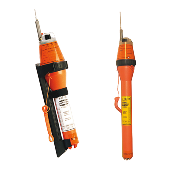
• COSPAS/SARSAT emergency EPIRB for manually operation. The purpose of the Tron 45S and Tron 45SX is to give a primary alarm to the search and rescue authorities. The EPIRB gives an immediate alarm when activated, transmitting the ID of the vessel in distress. Care must be taken not to activate the EPIRB unless in an emergency situation, in such cases the user will be held responsible. -
Page 14: Options Tron 45Sx
Battery, Tron 45SX, 5 years maintenance kit 97814 Antenna 97791 Label, battery 98955 Users manual for Tron 45S/SX Standard supply 97796 Tron 45S Pos.: Specification: Quantity EPIRB Tron 45S complete main unit 98955 Users manual 1.5.1 Options Tron 45S Pos.: Specification: 99897 Programming 97798 Container 97797... -
Page 15: Spare Parts Tron 45S
LUT. For the 121.5 MHz signal the satellite must be within line of sight of both the Tron 45S/SX and a ground station. The ground station or LUT has a 2500 km satellite reception radius centred at the LUT. -
Page 16: Distress Location Determination
Tron 45S/SX is kept up to date with data on the ship (nationality, call sign, etc.), to minimize the time from an alarm to the start of the search and rescue operation. -
Page 17: Technical Specifications
Tron 45SX: X-97770 Lithium, 5 years service life. 4 pcs. SAFT LSH20 Lithium- Thionyl chloride (Li-SOCL2) Operating Life: More than 24 hours at -20ºC. (Tron 45S). More than 48 hours at -20ºC. (Tron 45SX). Material housing: Polycarbonate with 10% fibreglass. -
Page 18: Homing Transmitter
A9, AM sweep tone between 300Hz and 1600Hz. Sweep range: 700 Hz, Sweep rate: 2.5 Hz. Stability: 10 ppm over temperature range. Antenna: Omni-directional. 2.4 BRACKETS 2.4.1 Brackets Tron 45S 2.4.2 Bulkhead bracket (Bmb) X-82224 Dimensions: Height: 380 mm Width: 100 mm... -
Page 19: Functional Description
FUNCTIONAL DESCRIPTION 3.1 Tron 45S/SX Tron 45S/SX may be split into the following main parts: 1. Electronic unit with antenna 2. Battery unit 3. Screw ring with gasket 3.2 Electronic unit with antenna. The electronic unit consists of two printed circuit boards which are mounted in the upper housing. -
Page 20: Installation
MAGNETIC FIELDS THAT COULD ACTIVATE THE BEACON. When the Tron 45S/SX is mounted in the brackets, it will operate as a manual unit. This bracket is typically used to store the EPIRB inside the wheelhouse or other protected areas of the ship. When the Tron 45S/SX is mounted in the brackets, it must be manually removed before any operation can take place, therefore the bracket should be mounted in an easily accessible place where it can be removed in a hurry in case of an emergency. -
Page 21: Operation Instructions
OPERATION INSTRUCTIONS 5.1 Operation of the Tron 45S When the Tron 45S is mounted in the Bulkhead mounting bracket (Bmb) it is a safety switch in the battery compartment that will prevent activation. This safety switch can be released by one action allowing the beacon to be manually activated in the bracket by a second action, activating the main switch. -
Page 22: Epirb Main Switch
The red indicator lamp and the Xenon flash on the main board will start operating, indicating that the EPIRB is active. Testing Tron 45S/SX The beacon must be removed from the bracket or container before testing can be performed. Turn the switch to the «TEST» position. The red indicator will start flashing for approx. 15 sec. -
Page 23: Battery Disposal
* Applicable to France 6.1.6 RECYCLING Send to authorized recycling facilities, eventually through a licensed waste carrier. TRON 45S/SX SELF TEST Remove the EPIRB from the bracket. Press the spring-loaded switch on top of the EPIRB to “TEST” position. Keep hands and objects away from the antenna. -
Page 24: Maintenance Of Jotron Epirb
EPIRB Battery and the Hydrostatic Release Mechanism. Check the presence of a firmly attached lanyard in good condition and that it is neatly stowed and is not tied to the vessel or the mounting bracket. If the Tron 45S/SX is... -
Page 25: Epirb Error Messages
EPIRB ERROR MESSAGES If the self-test detects a fault in the EPIRB module one or more of the following indications are shown: Flashing LED for 15 sec. followed by one (1) flash, no Xenon flash: Error: Low power on 406 MHz transmitter Flashing LED for 15 sec. -
Page 26: Figures
FIGURES SIGNAL DETECTION See chapter 1.6.1 and 1.6.2. Figure 7.1.a Figure 7.1.b 98955_UM_ 45S/SX_E... -
Page 27: Bracket Drawings
Bracket drawings 7.2.1 Bracket, aluminium 98955_UM_ 45S/SX_E... -
Page 28: Bulkhead Bracket
7.2.2 Bulkhead bracket 98955_UM_ 45S/SX_E... -
Page 29: Mb45 Bracket
7.2.3 MB45 bracket 98955_UM_ 45S/SX_E... -
Page 30: Manual Operation Of The Tron 45Sx
Manual operation of the Tron 45SX See chapter 5.2 98955_UM_ 45S/SX_E... - Page 31 98955_UM_ 45S/SX_E...
-
Page 32: Replacing Battery Module
REPLACING BATTERY MODULE See chapter 6.1.2 98955_UM_ 45S/SX_E... -
Page 33: Notes
NOTES 98955_UM_ 45S/SX_E... - Page 34 98955_UM_ 45S/SX_E...
-
Page 35: Service Agents
SERVICE AGENTS Please look at www.jotron.com for Marine Service Agents. JOTRON Group subsidiary companies: Jotron UK Ltd. Crosland Park, Off Crowhall Road Cramlington Northumberland NE23 1LA United Kingdom Tel +44 1670 712000 Fax +44 1670 590265 E-mail: sales@jotron.co.uk JOTRON Asia Pte. Ltd. - Page 36 98955_UM_ 45S/SX_E...
Need help?
Do you have a question about the Tron 45S and is the answer not in the manual?
Questions and answers