Table of Contents
Advertisement
Quick Links
Advertisement
Table of Contents

Related Manuals for jotron TR-2600


Summary of Contents for jotron TR-2600
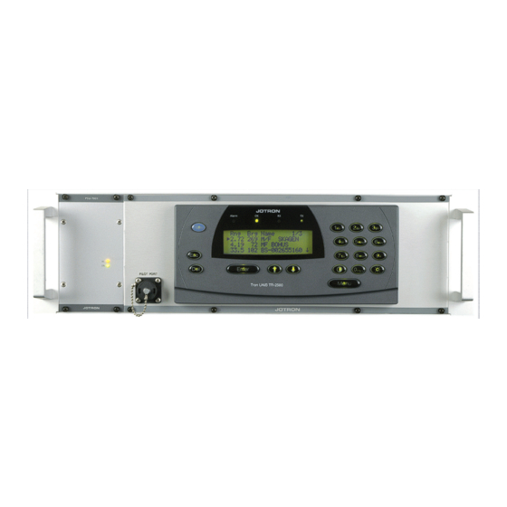
- Page 1 OPERATION AND INSTALLATION MANUAL TR-2600 AIS BASE STATION www.jotron.com...
- Page 2 EC Declaration of Conformity, available at www.jotron.com Abbreviations and definitions Antenna Changeover Unit AIS -Automatic Identification System. A shipborne broadcast transponder system in which ships continually transmit their position, course, speed and other data to other nearby ships and shoreline authorities on a common VHF radio channel.
- Page 3 See COURSE OVER GROUND COURSE OVER GROUND Course made good relative to the sea bed. CURSOR A flashing rectangle superimposed on a character position in the display window, indicating that a character may be entered in that position, or that the existing character may be changed via the keyboard. DEFAULT A condition that the navigator assumes automatically if no other condition is initiated by the operator.
- Page 4 Greenwich Mean Time. See also UNIVERSAL TIME COORDINATED. GPS SYSTEM TIME Time corrected to Universal Time Coordinated (UTC) and used as the time standard by the user segment of the GPS system. HEADING The direction in which the vessel is pointed, expressed as angular distance from north clockwise through 360 degrees. HEADING should not be confused with COURSE.
- Page 5 Man Machine Interface NMEA National Marine Electronics Association. The NMEA electronics interface specifications have been developed under the auspices of the Association. The NMEA 0183 is an internationally recognized specification for interfacing marine electronics. NMEA 0183 version 2.3 is identical to lEC 61162-1. POLLED MODE A transponder is in a polled mode during a request-response session only.
- Page 6 SET AND DRIFT The direction and the speed of the water over ground (current). SIGNAL- TO-NOISE RATIO (SIN) Quantitative relationship between the useful and non-useful part of the received satellite signal. A high SIN indicates a good receiving condition. S/N See SIGNAL- TO-NOISE RATIO SOFTWARE Values programmed and preloaded into memory.
- Page 7 Amendment Record AMENDMENT INCORP. DATE PAGE(S) VERSION REASON FOR CHANGE 08.07.2004 22.09.2004 1,4,64-66 28.09.2004 Page 63 of total 71 27.10.2004 28.02.2005 Removed signal converters. Edit txt. Added SW & HW versions. 18.03.2005 Removed SW & HW versions. Added drawing p.46 09.10.2006 Kontroll med manualer.doc Included errata.doc v.F...
- Page 8 1. Do not place liquid-filled containers on top of the equipment. 2. Immediately turn off the power if water or other liquid leaks into the equipment. Continued use of the equipment can cause fire or electrical shock. Contact a Jotron AS agent for service.
-
Page 9: Table Of Contents
LAN connections ..........................3-3 Every TR-2600 has it’s own BSC ....................3-3 3.3.1 3.3.2 One BSC controlling several TR-2600 over LAN, alternative #1 ..........3-4 3.3.3 One BSC controlling several TR-2600 over LAN, alternative #2 ..........3-5 Redundant system ..........................3-6 INSTALLATION ............................ - Page 10 Config Menu ..........................5-12 EQUIPMENT LIST ........................... 6-1 Standard supply 80400 ......................... 6-1 Optional supply ............................ 6-1 WIRING AND CONNECTIONS ......................7-1 TR-2600 AIS transponder, rear connections ..................7-1 7.1.1 VHF Antenna Connector ......................7-1 7.1.2 GPS Antenna Connector ......................7-1 7.1.3...
-
Page 11: General
The AIS BS is capable of exchanging navigation and Base Station data to/from ships and other costal stations through VHF Data Link (VDL). To be able to operate, the TR-2600 Transponder needs commands from a Base Station Controller (BSC), which may be connected to a Management System. -
Page 12: Tr-2600 Description
Tron AIS against the GPS system or against other transponders in the AIS system. Embedded Controller(EC) The EC module is the communication centre for the Tron TR-2600 Transponder: analysing data, building and controlling data base, communication with external units and controlling RX and TX messages into the right time slots. -
Page 13: Connector Board
The AIS BS transponders data as specified ITU on frequencies set up by the BSC. The VHF transmit power is set automatically at 2W or 12.5W. System standards The TR-2600 AIS BS complies with: IEC 61108-1 (1996) IEC 61162-1 (2000), -2 (1998) IEC 62320-1 draft 05.05.2004... -
Page 14: Specifications
2.1.1 Interfaces Serial: 9-pin RS-232 , 38400 baud LAN: Connector RJ45 female connector Protocols: TCP and UDP TR-2600 transponder Supply voltage: 24 VDC +30% / -10% (or 110-240v w/AC-DC converter) Power consumption: <100W Operating temperature: -15°C to +55°C Environmental: IP64... -
Page 15: Integrated Gps
2.2.2 Integrated GPS No of Channels: 12 channels parallel Tracking: 12 channels simultaneously Frequency: L1 - 1575.42 MHz RX code: C/A code Velocity: > 500 m/s Acceleration: Up to 5G Accuracy: Horizontal: < 3 meters (CEP) 5 meters 2dRMS < 5 meters (SEP) DGPS: <... -
Page 16: Tdma Transmitter
TDMA Transmitter Frequency Error : < +/- 0.5 kHz Frequency Range : 156-162.025MHz Channel Switching Time : Less than 25 ms. Carrier Power : The nominal levels for the two power settings 2W and 12.5Watts. With power deviation no more than +/-0.5dB under normal conditions and +/-1.0dB under extreme conditions. -
Page 17: Tdma Receivers
TDMA Receivers Frequency Error : +/-3ppm Frequency Range : 156-162.025 MHz : 20% at –107dBm (n.c.) Packet Error Rate, 25kHz Operation 20% at –101dBm (e.c.) Data transmission bit rate : 9600 bits/s +/- 50ppm. Receive BT-product, 25kHz channel : 0.5. GMSK Receive BT-product, 12.5kHz channel : 0.3/0.5. -
Page 18: Power Supply Unit, Front View
Power Supply Unit, Front view. PSU-7002 Figure 2.6, Power supply unit - front view «AC» LED Shows that the PSU is operating on AC mains power. «ON» LED Indicates that the PSU is switched on. 82695_Op&Ins MAN_TR2600_K... -
Page 19: Power Supply Unit Rear Connections
2.6.1 Power Supply Unit Rear Connections. Figure 2.6.1, Power supply unit - rear view DC Input Connector This connector is connected to an external DC backup supply (21.6 - 31.2 VDC). A is the positive connection and B is the negative. DC Output Connector This connector is connected to the transponder. -
Page 20: Description Of Power Operation
AC Input Connector Input for external AC. AC is input between A and C, B is chassis ground. The voltage range is from 110 to 240 VAC ± 10%. 2.6.2 Description of power operation The AIS BS is designed to operate from both AC and DC supply. Normally AC is the main supply and DC is the backup supply. -
Page 21: Tr-2600 Ais Base Station Configurations
BSC can be connected to a network and be a part of AIS BS system. See below. In this configuration, every BSC controls only one TR-2600 and to be a part of an AIS shore station network, it is also required LSS (Logical Shore Station) and ASM (AIS Service Management). -
Page 22: Using Lan Interface
To get the TR-2600 running towards a Base Station Controller, please do the following steps: 1. Connect the TR-2600 to the network by the RJ-45 connector in the adapter in the back of the unit. The adapter is connected to the 9-pins D-sub labelled “LAN”. -
Page 23: Lan Connections
LAN connections When using this port, TR-2600 can be connected to a BSC in several ways, and below are a couple of examples showing this: 3.3.1 Every TR-2600 has it’s own BSC Site #1 Base Station Controller (BSC) VHF & GPS Antenna... -
Page 24: One Bsc Controlling Several Tr-2600 Over Lan, Alternative #1
3.3.2 One BSC controlling several TR-2600 over LAN, alternative #1 Site #1 Base Station Controller (BSC) VHF & GPS Antenna Base Station Controller AIS BS (BSC) LAN using UDP/IP or TCP/IP Protection and filters Router/Gateway Site #2 HUB/Switch VHF & GPS Antenna... -
Page 25: One Bsc Controlling Several Tr-2600 Over Lan, Alternative #2
3.3.3 One BSC controlling several TR-2600 over LAN, alternative #2 Site #1 VHF & GPS Antenna Router/Gateway AIS BS External network Protection and filters LAN using UDP/IP or TCP/IP Site #2 VHF & GPS Antenna Router/Gateway AIS BS Protection and filters... -
Page 26: Redundant System
Redundant system A Base station can be built up as a redundant system with two transponders with separate GPS antennas for each transponder, an ACU (antenna changeover unit), and a UPS supply. See paragraph 2.6.2 for redundant power of the AIS BS. The software to support a redundancy solution is implemented in the transponder units, and the solution does not require any hardware modifications. -
Page 27: Installation
81. The frequency spacing between them is 300 kHz or 0.3 MHz. Measurement done on the TR-2600 transponder shows that blocking will occur if the signal from channel 81 on the location of the AIS antenna is more than –11 dBm, if the wanted signal of the AIS is at a level of –101 dBm. - Page 28 30 meter vertical should be sufficient. All these numbers are calculated from the specs. of TR-2600, so what the blocking numbers are for the VHF base station on the same site, will depend on the equipment. But these distances can be reduced using cavity filters, but as cavity filters will only let the correct frequencies through, the will also have an insertion loss between 0.5 to 2 dB per.
- Page 29 Horizontal separation distance: Other VHF antenna VHF antenna for AIS: or GPS antenna See article in chapter 4 explaining an example. >aa meters Vertical separation distance and distance from mast or other object of metal: Vertical separation distance: VHF antenna for AIS: VHF antenna for AIS: See article in chapter 4 explaining an example.
-
Page 30: Cabling
Cabling The cable should be kept as short as possible to minimize signal attenuation. The table below gives recommendations on cables that can be used for the GPS antenna connections: Type Attenuation Remark @1.5 GHz (dB/100m) RG58 Default for use if length< 20 m and antenna = Procom GPS4 RG214 If combined GPS/VHF antenna from either Procom or Comrod is used, this or better can be used... -
Page 31: Cable Installation
4.2.1 Cable installation All outdoor installed connectors on coaxial cables should be fitted with preventive isolation such as vulcanizing tape to protect against water penetration into the antenna cable. Coaxial cables should be installed in separate signal cable channels/tubes and at least 10 cm away from power supply cables. -
Page 32: Operation
24V DC is needed. The DC input voltage must be within 24VDC +30% / -10%. The power consumption is 60W. At startup, the TR-2600 will look for connected sensors and equipment for 20 –30 seconds. The display will show: Loading …... -
Page 33: Description Of Keys
Description of keys : Not used Menu : Show main menu Enter : Accept current setting. Takes you one menu level forward. Enter sub-menu : Escape from current menu without saving. Takes you one menu level back. : Delete character at cursor ... -
Page 34: First Configuration Of Tr-2600 Transponder
First configuration of TR-2600 transponder 5.3.1 RS422 configuration If the RS422 ports on ”External display” are used to communicate with a BSC, there is nothing necessary to configure before use. Just go further to chapter 5.4. 5.3.2 LAN configuration Press [Menu] key to enter “Main menu”. - Page 35 The Port number is default to “5000”, but can be altered to what the BSC needs. These must of course be the same on the TR-2600 and the BSC (Base Station Controller) Press [Enter] when done, you will also be asked for “Password”, and the correct password must be entered to continue, otherwise the same menu will appear.
- Page 36 Select “Own IP address” then [Enter] key Now the IP address of the TR-2600 can be entered: Menu: BSC LAN Addr 1 IP = 0.0.0.0 2 Port = 51 00 As in “Set Own IP address “ in the previous chapter, the settings must also be set here.
-
Page 37: Tr-2600 Transponder Menus
TR-2600 Transponder Menus 5.4.1 Menu Flowchart Main Menu 1 Current Sensors Rng Brg Name: 2 Internal GPS 1384 124 NIKITA 3 Messages Menu 1754 124 COLOR FESTIV 4 Diagnostic 99.1 5 Config 098 PETER VESSEL Enter key 1 to 5... -
Page 38: Tr-2600 Transponder, Readout And Configuration
TR-2600 Transponder, Readout and Configuration 5.5.1 Display received vessels Normal use operational display Name of the Bearing of the Range to ship in received ship. nautical miles received ship.. Rng Brg Name: 1384 124 NIKITA 1754 124 COLOR FESTIV 99.1 098 PETER VESSEL Select the name of the ship by pressing [arrow down] key and [Enter] key. -
Page 39: Current Sensors / Dynamic Data Menu
5.5.2 Current Sensors / Dynamic Data menu Main Menu 1 Current Sensors 2 Internal GPS 3 Messages 4 Diagnostic 5 Config Select “Current Sensor” with numeric key [1] or press [Enter] key. Menu: Current Senso LAT: --- LON:--- Pos. Accur.: Low Pos. -
Page 40: Messages Menu
5.5.4 Messages Menu From the “Main Menu” select “Message” by pressing numeric key [3] or [arrow down] key and [Enter] key. Menu: Messages 1 Read Messages 2 Send Messages Select “Read Messages” by pressing [Enter] key or numeric key [1]. Menu: Received msg 0/0 The number of received messages will show in upper right corner. -
Page 41: Diagnostic Menu
5.5.5 Diagnostic Menu From the “Main Menu” select “Diagnostic” by pressing numeric key [4] or [arrow down] key and [Enter] key. Menu: Diagnostic 1 BIIT 2 Alarm 3 System Indicators 4 History 5 SW Versions 6 Service This menu gives access to different submenus for readout of parameters. The only submenu who can give access to changes is the “Service”... - Page 42 Menu: Indicators UTC Clock ok This menu shows the momentarily status if sensor is connected. Press [Esc] key to go one step back. Select “History” menu by pressing numeric key [4] or [arrow down] key and press [Enter ] key. Menu: History Off 19 Jan 2038 03:14 On 30 Dec 2030 02:07...
-
Page 43: Config Menu
Select “Config” menu by pressing numeric key [5] or [arrow down] key and press [Enter ] key. Menu: Config 1 I/O Ports 2 Buzzer 3 Change Password 5.5.6 Config Menu When entering a submenu in the “Config menu” you have to enter password 2. When the password is accepted you have access to all parameters in the “Config menu”. - Page 44 Select speed using [arrow up/down] keys and press [ Enter] key Repeat the prosedure for all ports. Press [Esc] key to return Confirm changes by [arrow up/down] keys and press [ Enter] key Selection of Own and BSC IP address is described in chapter 5.3 Save Changes ? = No = Yes Select “Buzzer”...
-
Page 45: Equipment List
6 EQUIPMENT LIST Standard supply 80400 Name Type Stock No. Qty. Remarks 19`` Rack Tray Schroff 98825 19`` Rack Tray Mounting Kit 80587 Transponder unit TR-2600 80401 PSU 7002 LEP240F-36 99135 81533 Plug Kit Optional supply Name Type Stock No. -
Page 46: Wiring And Connections
7 WIRING AND CONNECTIONS TR-2600 AIS transponder, rear connections 7.1.1 VHF Antenna Connector This is a BNC type antenna connector to be connected directly to an external VHF antenna or antenna splitter to receive and transmit VHF frequencies. For further information see section 10.5 and 10.7. -
Page 47: Programming Connector
7.1.6 Programming Connector Factory use only 7.1.7 Junction Box Connector This is a 37 pin D-sub female connector for connections between the transponder and sensor, RS422<->RS232 converter and RS422 <->LAN converter (TCP/IP). It is also a LAN port with UDP protocol on this connector 7.1.8 LAN Connector This 9 pin D-sub connector is described in chapter 7.4. -
Page 48: Junction Box Connector, 37 Pin D-Sub
Junction Box Connector, 37 pin D-sub Pin Nr. Name Function In/Out AIS TD1-B Reserved AIS TD1-A Reserved AIS 1 in (B) AIS RD1-B (External GPS) AIS 1 in (A) AIS RD1-A ( --------“---------) AIS TD2-B Reserved AIS TD2-A Reserved AIS 2 in (B) AIS RD2-B AIS 2 in (A) AIS RD2-A... -
Page 49: Description Of Lan Connector (Udp)
Description of LAN connector (UDP) Contains Ethernet 10Mbit Twisted pair interface and RS232 serial port with Tx and Rx. Service connector, 9 pins Dsub: Name Function In/Out Ether_Tx+ Ethernet Transceive Data+ Ether_Tx- Ethernet Transceive Data- Ether_Rx+ Ethernet Receive Data+ Ether_Rx- Ethernet Receive Data- Ground PC_UART_Tx... -
Page 50: Connection To Pc Serial Port Using Rs422 To Rs232 Converter
Connection to PC serial port using RS422 to RS232 converter On the RS232 side of the converter, a standard RS2323 extender cable must be used. RS422 to RS232 converter. ADAM 4520 TR-2600 Junction 37-pin D-sub Names RD-A (-) RD-B (+) -
Page 51: Alarm Messages
8 ALARM MESSAGES See tables of alarms and notifications in Technical Manual paragraph 1.4 Receiver malfunction If the error messages “Rx1” or “Rx2” appears on the LCD Display, this indicate that the test of the TDMA receivers 1 or 2 has failed. 8.1.1 Receiver tests Every time a transmission is done and the receiver is on the same channel as the transmitter, the receiver measures the signal level (RSSI) and will give an alarm if too low signal level is obtained. -
Page 52: List Of Vhf Channels
LIST OF VHF CHANNELS Channel Channel Channel Channel Frequency Frequency Frequency Frequency 156.3000 1021 157.0500 1279 156.9775 2219 161.5625 156.4000 1022 157.1000 1280 157.0375 2220 161.6125 156.4500 1023 157.1500 1281 157.0875 2221 161.6625 156.5000 1024 157.2000 1282 157.1375 2222 161.7125 156.5500 1025 157.2500... -
Page 53: Outline Drawings
10 OUTLINE DRAWINGS 10.1 TR-2600 AIS BASE STATION 82695_Op&Ins MAN_TR2600_K 10-1... -
Page 54: Tr-2600 Ais Transponder
10.2 TR-2600 AIS Transponder 82695_Op&Ins MAN_TR2600_K 10-2... -
Page 55: Procom Cxl 2-1/L Maritime Vhf Antenna With Flg Bracket
10.3 Procom CXL 2-1/l Maritime VHF Antenna with FLG Bracket 82695_Op&Ins MAN_TR2600_K 10-3... -
Page 56: Procom Gps 4 Antenna
10.4 Procom GPS 4 Antenna 82695_Op&Ins MAN_TR2600_K 10-4... -
Page 57: Bnc Connector 95299, Suhner 24Bnc-50-2-13/133Ne
10.5 BNC connector 95299, Suhner 24BNC-50-2-13/133NE 10.6 FME Connector Female 80588, Holund 40100 82695_Op&Ins MAN_TR2600_K 10-5... -
Page 58: Bnc Connector Male 80577, Suhner 11Bnc-50-2 / 133Ne
10.7 BNC Connector Male 80577, Suhner 11BNC-50-2 / 133NE 10.8 TNC Connector Male 80578 Suhner 11TNC-3-6 / 133NE 82695_Op&Ins MAN_TR2600_K 10-6... -
Page 59: N Connector Male 80581, Suhner 11N-50-7-5 / 133Ne
10.9 N Connector Male 80581, Suhner 11N-50-7-5 / 133NE 10.10 24VDC Power Connector 81509, AMP C091AT3261001 82695_Op&Ins MAN_TR2600_K 10-7... -
Page 60: Registration Form
Place Date Signature Please fill in with capital letters This form must be returned to Jotron AS, Fax.: + 47 33 12 67 80 (attention service department) in order to have a valid 24 months product warranty. 82695_Op&Ins MAN_TR2600_K 11-1... - Page 61 82695_Op&Ins MAN_TR2600_K 11-2...
Need help?
Do you have a question about the TR-2600 and is the answer not in the manual?
Questions and answers