Advertisement
Quick Links
DM-I001-240918 Getting started guide
Welcome to your new SKIPPER Product
Congratulations with your Jotron SKIPPER 10.1 inch Control Unit.
This Package is factory configured for the following product
Part Number
EML1200-SA
EML1100-SA
CU-M101-SA
Your Package contains
Qty
Part
1
CU-M101-SA
1
M-KIT-CU-M101
1
M-KIT-XBEEP
1
DM-I001
1
DM-E004-SA or DM-
D020
This getting started guide Follows:
1 Install/Mount the system
2 Define the System (CU-M101-SA only)
3 Configure the system (All systems)
4 Check your system
These instructions are also available in mobile format by
scanning here
Product Name
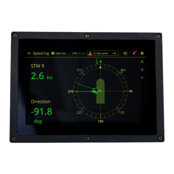
EML1200 Control Unit for Dual Axis Electromagnetic STW
Speedlog
EML1100 Dual Axis Electromagnetic STW Speedlog
CU-M101-SA Dual Control Unit
Description
10.1" Control unit
Mounting kit
External beeper kit
Getting started instruction
User manual for EML or DL
P a g e
This product
(if checked)
Photo
This document
| 1
Advertisement

Summary of Contents for jotron SKIPPER EML1200-SA
- Page 1 DM-I001-240918 Getting started guide P a g e Welcome to your new SKIPPER Product Congratulations with your Jotron SKIPPER 10.1 inch Control Unit. This Package is factory configured for the following product Part Number Product Name This product (if checked)
- Page 2 DM-I001-240918 Getting started guide P a g e 6 x M5 torx Pan head 1. Install/Mount the system Screws (ISO 14583) Black Make a cutout of size 257x 182 in an area of minimum 287x210mm Length 21.8mm , Thread into the back plate 16.5 Alternative 6 x Self tapping screw ood, plastic &...
- Page 3 DM-I001-240918 Getting started guide P a g e M-KIT-XBEEP-CU- Mount the External beeper (if required) M101-SA Drill a hole diameter 6.5-7.0mm Clean both surfaces with attached wipe Attach the Sticker to the Buzzer Attah to the rear of the plate , take care to align the holes.
- Page 4 DM-I001-240918 Getting started guide P a g e X1a and X1b 24VDC Attach the IO connectors as required (4.2 in manual) Power connector Degson 2EDGKD-5.08- 02P-14-00A(H) X2 USB Type A (Non isolated) Use Isolator GC-202-SA for long term USB installations X3 &...
- Page 5 DM-I001-240918 Getting started guide P a g e Attach the power Connection of the System (4.2 in manual) connector(s) Power stability is required. This is acheived using either A secondary power. either 2 24VDC connectors by using a UPS as a failsafe The system requires <20W and Power to the system and...
- Page 6 DM-I001-240918 Getting started guide P a g e Anchor the cables, M-KIT- Mount the unit (4.2 in manual) using the included cable ties Ground The Unit to ships Chassis using the Grounding spade. Note the serial number of the unit and mount the unit in place Serial Number: ________ (6 digits)
- Page 7 Click on the QR code, if a Product option is purchased, the code will be available here, If no code is available contact Jotron SKIPPER to purchase the required Product code. If the product option is not shown on Ensure Software is installed or download...
-
Page 8: Set Up The System
DM-I001-240918 Getting started guide P a g e Set up the system Click on the Users Button Sign in Enter User ‘admin’ and Password <serial number> e.g 1234 Check ‘Stay Signed in’ And Press sign in. The system signs in with full access. (Note, Passwords and users should be changed before HAT/SAT ) - Page 9 DM-I001-240918 Getting started guide P a g e Configure the system Using the Menu button (top left) select settings setup in the menu dropdown Go to system and enter the vessels parameters. If you use only one power input, disable the unused one. If you supply power to the sensor from another unit (JB40POW) disable the sensor Power.
- Page 10 DM-I001-240918 Getting started guide P a g e | 10 In addition add vessel parameters, IMO number, Bottom sensor type and Bottom equipment Serial number (If these are not enterd you will get reminders on startup or exit of the system setup screen)
- Page 11 DM-I001-240918 Getting started guide P a g e | 11 Popups on startup. Popups You may get the following: Beta Version approval – Accept terms and close the popup (Check for updates using QR code) Foreign network – Select a safe point in the network to allow the system to detect unauthorized cable being plugged into the system, Approve...
- Page 12 DM-I001-240918 Getting started guide P a g e | 12 Serial Input/ output In Communications setup, Configure the IO as required. Select the outputs required, and the Baud rate for the 2 serial ports (NMEA/IEC61162-1) Ethernet 2 Ethernet ports using IEC61162-450 and supporting IEC-61162-460 Network is Blocked on startup, Select a safe IP address on your...
- Page 13 DM-I001-240918 Getting started guide P a g e | 13 Alerts The system has alerts, these are not obligatory in most installations (check class regulations) These can be disabled, or they can be given different categories. (Off, Caution, Warning, W+Escalation) Connect the CAM/BAM system by defining the Alert group Connect to the CAM/BAM SFI.
- Page 14 DM-I001-240918 Getting started guide P a g e | 14 To show or prove the system works Harbour Acceptance Test (HAT) you can do the following: 1. Test Sensor display Set a speed and Run a fixed speed simulation ‘ Simulate speed’ 2.
- Page 15 DM-I001-240918 Getting started guide P a g e | 15 Self test will test the internal Self Test parameters and connections of the system CPU load How much the system is doing RAM useage – How much memory is in use Ethernet Load If too high the system may slow down Sensor output voltage/Current...


Need help?
Do you have a question about the SKIPPER EML1200-SA and is the answer not in the manual?
Questions and answers