
Related Manuals for jotron MPA 1600


Summary of Contents for jotron MPA 1600
- Page 1 USER AND INSTALLATION MANUAL Compact MPA Compact MPA Public address and general alarm system www.jotron.com...
-
Page 2: Table Of Contents
END OF LIFE DISPOSAL GUIDANCE LIST OF ABBREVIATIONS AND DEFINITIONS DOCUMENT REVISION LOG GENERAL DESCRIPTION MPA 1600 OPERATION UNIT MPA 1601 PA CONTROL UNIT MPA 1603 GA ALARM PANEL MPA 1605 PAGA ACCESS PANEL MPA 1606 PAGA ACCESS PANEL - 19”/ FLUSH MOUNTING MPA 1643 PAGA ACCESS PANEL - WALL/DESK MOUNTING IN E.X AREAS. - Page 3 User and Installation Manual Compact MPA 5.1.2 PA CONFIGURATION, PASSENGER VESSELS 5.1.3 PA/GA CONFIGURATION, ALL VESSELS INSTALLATION GUIDE 5.2.1 PLANNING 5.2.2 GENERAL 5.2.3 LOUDSPEAKER SELECTION AND SOUND PRESSURE LEVEL 5.2.4 NUMBER OF LOUDSPEAKERS 5.2.5 CABLE ARRANGEMENT 5.2.6 ZONES 5.2.7 AMPLIFIERS 5.2.8 SHORT CIRCUIT PROOF LOUDSPEAKERS 5.2.9...
- Page 4 INTRODUCTION BRIEF SYSTEM DESCRIPTION 8.3.1 GENERAL 8.3.2 CENTRAL EQUIPMENT 8.3.3 ACCESS & CONTROL PANELS FUNCTIONAL TESTING OF UNITS 8.4.1 MPA 1600 OPERATION UNIT 8.4.2 MPA 1601/1643 TALK UNITS 8.4.2.1 NORMAL PAGING 8.4.2.2 EMERGENCY PAGING 8.4.2.3 INDICATORS 8.4.2.4 PRIORITY BY NORMAL PAGING "PA"...
-
Page 5: Introduction
User and Installation Manual Compact MPA 1 INTRODUCTION The Compact MPA-system is a marine and offshore Public Address system. It meets the requirements for PA/GA, and enter- tainment, distribution onboard ships and mobile offshore units. The system conforms to SOLAS, IMO and IEC regulations. Based on modular design and flexible configuration, it covers a wide range of installation complexities. -
Page 6: Service And Warranty
(24) months from the date of delivery (unless stated otherwise and confirmed in writing) CONDITIONS: Jotron AS is given full particulars in writing of any claim prior to the expiration of such a period and within fourteen days of the discovery of the alleged defect. -
Page 7: Document Revision Log
User and Installation Manual Compact MPA DOCUMENT REVISION LOG 06.07.17 Initial release 16.08.17 New layout 02.10.17 Uppdated IW-draving Issue Date Reason for Issue Author Approval... -
Page 8: General Description
User and Installation Manual Compact MPA 2 GENERAL DESCRIPTION 2.1 MPA 1600 OPERATION UNIT The MPA 1600 Operation Unit is the system central logic controller in the Compact MPA-system. It is designed for 19" 1 Unit rack mounting. Features: •... -
Page 9: Mpa 1601 Pa Control Unit
User and Installation Manual Compact MPA 2.2 MPA 1601 PA CONTROL UNIT The MPA 1601 is a full facility operator control unit in the MPA system. It is designed for flush mounting. Features: • Microphone options are Gooseneck, or Handheld. •... -
Page 10: Mpa 1606 Paga Access Panel - 19"/ Flush Mounting
MPA 1600 with ship-cables. Refer to chapter 4.4 and 9.3 for all detailed information. 2.8 AMPLIFIER 1671 The Compact MPA system is designed to be used with the Jotron amplifier 1671. Features: • Thermal and overload protection, balanced input. •... -
Page 11: Loudspeakers
Outer dimensions: 144 x 144 mm. Operating voltage: 24VDC supplied from the MPA1600 Operation Unit. Current drain maximum: 300mA. (integrated in the MPA 1600) Microphone input level: 10mV typical (dynamic mic.) Ingress Protection (IP): Compass safe distance (standard) 80 cm... -
Page 12: Mpa 1603 Ga Alarm Panel
AC 115V (110/120) 50Hz/60Hz (backup) DC 24V Maximum current drain AC (110V) Dimensions W:483 x H:44 x D:320 mm Weight 5.5 Kg. 3.5 CABINETS Type: Jotron Compact cabinet 19” 5x1U Dimensions W:585 x H:618 x D:470 mm Weight 30 kg. Ingress Protection (IP) -
Page 13: Performance
User and Installation Manual Compact MPA 4 PERFORMANCE 4.1 GENERAL ALARM The General Alarm tone in the Compact MPA system consists of seven short followed by one long tone burst. Each short tone has approximately 1 sec. duration, each pause between tones approximately 1 sec. and the long tone has 7 sec. duration. The alarm signal sequence is continuously repeated. -
Page 14: External Interfaces
User and Installation Manual Compact MPA 4.4 EXTERNAL INTERFACES The Compact MPA PA/GA system is equipped with various control outputs for external equipment. This is intended for additional warnings and indicators. Ref. drawing in 9.3. Current / Terminals Name Description Input/output Interface Voltage... - Page 15 User and Installation Manual Compact MPA EMPA_ACT24V EM PTT is active Output Open collector source/sink 24VDC 40 mA EMPA_REF Pwr.Fail.no Power monitoring output, Output Dry contact output 0.3 A Normally Open Pwr.Fail.co Alarm Sync Out Alarm sequence monitor Output Dry contact output 0.3 A output Alarm Sync ref-...
-
Page 16: General Alarm Interface To Ship Whistle/Siren
User and Installation Manual Compact MPA Power - Audio + Bidirectional Electronically balanced audio input 2Vrms 15k Ω Audio - RS485 - Data communication tranceiver User Interface 4 Bidirectional 100 Ω channel RS485 RS485 + Power + Output Power supply output 24VDC 140 mA Power -... -
Page 17: Volume Override
User and Installation Manual Compact MPA 4.8 VOLUME OVERRIDE In addition to the entertainment mute functionality, the Compact MPA is equipped with a volume override signal as a relay driver output (Open Collector source/sink) which is activated during both GA and Emergency PA. This signal is used for reset- ting local entertainment (etc.) volume control settings related to the GA/PA system. -
Page 18: Cabinet Power Terminal Connections
User and Installation Manual Compact MPA 4.12 CABINET POWER TERMINAL CONNECTIONS 4.12.1 AC + DC VERSION The primary power source for the Compact MPA Cabinet is 230VAC with 24VDC as backup. 230VAC 24VDC Live 24VDC (fuse) 230VAC Neutral 0VDC 0VDC (fuse) MPA 24VDC backup (supplied from 1671) MPA 0VDC backup (supplied from 1671) 4.12.2 AC + AC VERSION... -
Page 19: Installation Procedure
User and Installation Manual Compact MPA 5 INSTALLATION PROCEDURE 5.1 INTRODUCTION 5.1.1 PA CONFIGURATION, CARGO VESSELS Compact MPA system installations onboard cargo vessels, where GA is not integrated into the PA system have no require- ment for duplication. All loudspeaker loops shall be arranged as closed loops. 5.1.2 PA CONFIGURATION, PASSENGER VESSELS Compact MPA system installations onboard passenger vessels are required to be duplicated in order to minimize the effect of a single failure. - Page 20 User and Installation Manual Compact MPA To ensure this, the Compact MPA system makes use of the industrial standardized 100 V line distribution system. This is a dis- tribution system that is based on a fixed line level (100V) and where the loudspeaker output power is determined by means of loudspeaker type and power tapping.
- Page 21 User and Installation Manual Compact MPA DNH HP15T:...
-
Page 22: Loudspeaker Selection And Sound Pressure Level
User and Installation Manual Compact MPA 5.2.3 LOUDSPEAKER SELECTION AND SOUND PRESSURE LEVEL The calculation of sound pressure level (SPL) is also dependant of distance from the loudspeaker: The calculation is according to the formula: SPL =A+(10·LOG (B))-(20·LOG (C)) WHERE: SPL: Sound Pressure Level figure at a specific point [dBA] Loudspeaker specific data - SPL figure at 1W / 1m (according to loudspeaker data sheet) dBA]... -
Page 23: Amplifiers
User and Installation Manual Compact MPA 5.2.7 AMPLIFIERS The number of loudspeakers, their tapping (actual power output) and, in some cases, the zone segmentation determines the necessary number of amplifiers in the amplifier pool. In a fixed line level (100V) system such as the Compact MPA, the requirement for amplifier power is exactly the same as the loudspeaker output figure. -
Page 24: Compass Safe Distance
This is a part of the system setup and must be determined either in the factory (FAT) or during System installation and commissioning. Configuration of the GA characterisics is an option within the MPA 1600 web configuration facility, which is described in section 6. -
Page 25: Power
User and Installation Manual Compact MPA 5.5 POWER The operating power is 115/230 VAC as primary, and 24VDC, alternatively 115/230 VAC as secondary. The Compact MPA system will automatically switch between primary and secondary power sources in case of power supply failure. A secondary power supply must be present at transition to emergency power supply in order to avoid the system boot sequence of approximately 30 seconds. -
Page 26: Fastening
User and Installation Manual Compact MPA 5.9 FASTENING Where applicable, the cables and the conductors shall be clamped to the structure with cable ties. 5.10 PRECAUTIONS Prior to, during, and after installation the equipment must be handled with care. And protected against acidic fluids, pollu- tion, moisture, impacts etc. -
Page 27: Connecting To Service Port
User and Installation Manual Compact MPA 6.2.1 CONNECTING TO SERVICE PORT Figure 1: Service Port The Service port exposed by the Compact MPA system is a standard RJ-45 connector. The computer intended for use with the web-configuration can be connected directly to this port via a standard Ethernet patch cable. -
Page 28: Setting A Static Address Locally
User and Installation Manual Compact MPA 6.2.2 SETTING A STATIC ADDRESS LOCALLY To access the web-interface, it is necessary to set a static IP address on the computer connected to the Compact MPA service port. In Windows, this can be performed in the Network Connections-screen (Control Panel > Network and Internet > Net- work Connections). -
Page 29: Configuration - General
User and Installation Manual Compact MPA 6.3 CONFIGURATION – GENERAL Figure 5: General Tab The “General”-tab allows users to set the name of the configuration, select if the system is a single system or a duplicated system (A/B) and view the versions of firmware components. The name of the configuration is a simple string describing the configuration in some way. -
Page 30: Configuration - Audio Output
User and Installation Manual Compact MPA 6.4 CONFIGURATION – AUDIO OUTPUT Figure 6: Audio Output The “Audio Output”-tab allows users to set up amplifiers, zone assignments, zone relays, signal monitoring, Modbus monitoring and the external PA output. The amplifier setup is used to set the zone assignments and amplifier type for all six amplifier outputs of the MPA1600. Please note that for the Compact MPA, at most three of these will be used. -
Page 31: Configuration - Audio Input
User and Installation Manual Compact MPA 6.5 CONFIGURATION – AUDIO INPUT Figure 7: Audio Input The “Audio Input”-tab allows users to set up external PA inputs and microphone stations. The external PA inputs can be set to any zone or set of zones, with a specified PA priority (lower is more important) and if the message should be recorded prior to playback. -
Page 32: Configuration - Control Units
User and Installation Manual Compact MPA 6.6 CONFIGURATION – CONTROL UNITS Figure 8: Control Units The “Control Units”-tab allows users to set the default zone selection for paging events, the attention tones for each paging type, optional attenuation for attention tones, as well as zone selections, alarm tones and priorities for each alarm accessible via the 1601/1603/1605/1606/1643 access panels. -
Page 33: Configuration - Users
User and Installation Manual Compact MPA 6.7 CONFIGURATION – USERS Figure 9: Users The “Users”-tab allows users to enable or disable access unit buses, set the paging priorities between different buses and enable or disable recording for paging events on individual buses. One bus may contain up to two 1601 and two 1603 access units or up two 1605/1606 access units. -
Page 34: Configuration - External Alarm Inputs
User and Installation Manual Compact MPA 6.8 CONFIGURATION – EXTERNAL ALARM INPUTS Figure 10: External Alarm Inputs The “External Alarm Inputs”-tab allows users to set the zone selection, alarm tone, alarm priority, synchronisation and other advanced options for alarm inputs from external systems. The External alarm input setup controls the zone or set of zones to include in the alarm, the alarm tone to use, the priority of the alarm and several advanced options. - Page 35 User and Installation Manual Compact MPA The activation parameter of the external input defines how long the input is to be considered triggered. If set to “Continuous”, the input is triggered as long as its state is asserted. If set to “Impulse” the input is triggered immediately when its state is asserted, and is not cancelled when the state is no longer asserted.
-
Page 36: Configuration - Snmp/Network
“public”. SNMP is typically used with Jotron RCMS, to perform remote monitoring of the MPA1600 and connected Phontech 1671 amplifiers. Please see the RCMS manual for how to add devices in the monitoring application. Please note that the settings in... -
Page 37: Configuration - Advanced
User and Installation Manual Compact MPA 6.10 CONFIGURATION – ADVANCED Figure 12: Advanced The “Advanced”-tab allows users to configure miscellaneous advanced settings for the MPA1600. This includes AGC and speech power booster, Alarm and PA/EMPA options, NORSOK mode, Alarm attenuation, trimming the end of recorded messages and alarm synchronisation timeouts. - Page 38 User and Installation Manual Compact MPA Alarm and PA/EMPA options contains the alarm block time, whether to allow PA messages to be upgraded to EMPA during an alarm and the ability of a new alarm to interrupt an EMPA message. The alarm block time is the time between the activa- tion of an alarm to when it is possible to give an EMPA message.
-
Page 39: Backup And Restore
User and Installation Manual Compact MPA 6.11 BACKUP AND RESTORE Figure 13: Backup and Restore The “Backup and Restore” screen allows users to take a backup of the current MPA1600 configuration and sound files or restore a previously stored backup to this system. Downloading a backup of the current configuration and sound files results in a .tgz with a filename matching the name given in the “General”-tab of the configuration. -
Page 40: Upload New Sounds
User and Installation Manual Compact MPA 6.12 UPLOAD NEW SOUNDS Figure 14: Upload new sounds The “Upload new sounds” screen allows users to upload new sounds to be used for attention tones and alarm messages. It is also possible to see the files currently installed on the unit. Please note that there is a fixed size of space available, so unused files may have to be removed prior to uploading replacement files. -
Page 41: Operating Procedure
„Please see the configuration-section for more details on how to set up the MPA1600. 7.3 OPERATING DESCRIPTION 7.3.1 EMERGENCY PAGING Emergency Paging (EM PA) is the highest priority paging method within the MPA 1600 system. 7.3.1.1 PRIORITY • EM PA overrides any audible entertainment channels within the system while active. -
Page 42: Description
User and Installation Manual Compact MPA 7.3.1.2 DESCRIPTION EM PA messages are always broadcast to all zones/areas in the system. EM PA is initiated from the 1601, 1605, 1606, 1643 access panels, by means of the EM PA button. This button is distinguished by a red colour. -
Page 43: Paging
User and Installation Manual Compact MPA 7.3.2 PAGING Normal paging (PA) is the second priority paging method within the MPA 1600 system. 7.3.2.1 PRIORITY • PA overrides any audible entertainment channels within the system while active. • PA overrides any external entertainment systems by means of an entertainment mute signal while active (see chapter 4.4 and 9.3). -
Page 44: General Alarm
User and Installation Manual Compact MPA Keep pressed continuously Optional: GOOSENECK GOOSENECK during the PA message. Without any Activate any zone MICROPHONE MICROPHONE (OPTION) (OPTION) optional preselection of zones, combination the zone selection is according to the preprogrammed setup Figure 16: Paging via 1601. ... -
Page 45: Commissioning Procedure - For The General Alarm/Public Address System Compact Mpa
The tests will also show that the basic performance requirements (e.g. Signal Levels and functions) are met. These commissioning tests are targeted towards a IMO/SOLAS certified system and relies on the MPA 1600 to configured to comply with those requirements. Please see the Prerequisites section of the Operating Procedure for details on the necessary configuration options. -
Page 46: Mpa 1601/1643 Talk Units
User and Installation Manual Compact MPA 8.4.2 MPA 1601/1643 TALK UNITS The 1643 unit is an EX variant of the MPA 1601 talk unit, and the procedure to test this unit is identical to the 1601. 8.4.2.1 NORMAL PAGING Paging may be performed in any combination of the six zones. Zones are selected by the MPA 1601 zone-keys, and activated by the PA-key. -
Page 47: Priority By Normal Paging "Pa
User and Installation Manual Compact MPA 8.4.2.4 PRIORITY BY NORMAL PAGING "PA" The MPA system is a single access system. Meaning that only one operator can use the system at any time. The priority is programmable by software. If operator I has higher priority than operator II, then operator I can override operator II. However, the operator II can override I with the use of Emergency PA (EM-PA) key. -
Page 48: Mpa 1603 Alarm Panel
8.4.4 MPA 1603 ALARM PANEL 8.4.4.1 ALARM SETTING The MPA 1600 can handle 4 different alarm types. The General Alarm is mandatory by the IMO/SOLAS specifications, the others are optional and thus of lower priority and significance. The alarms can be activated from the MPA 1603 alarm panel. All alarms will temporarily override any PA activity from any users. -
Page 49: Failure / Warning Outputs
In no cases should the sound level exceed 120 dBA. To ensure this, the MPA 1600 system makes use of the industrial standardized 100 V line distribution system. This is a distribution system that is based on a fixed line level (100V) and where the loudspeaker output power is determined by means of loudspeaker type and power tapping. -
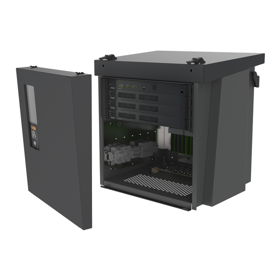
Page 50: Annex A
User and Installation Manual Compact MPA 9 ANNEX A 9.1 COMPACT MPA CABINET – MECHANICAL LAYOUT... -
Page 51: Wall Bracket Kit
User and Installation Manual Compact MPA 9.2 WALL BRACKET KIT... - Page 52 User and Installation Manual Compact MPA Notes: „ 8 pcs. M6 and 2 pcs. M5 treaded bolts required for mounting Compact Cabinet to wall. Pc. No. 3 & 4 are option for uneven or non-planar surfaces. Recomanded mounting sequence ( see illustrations in View A): Use Pc.
-
Page 53: Compact Mpa Cabinet - External Connection
User and Installation Manual Compact MPA 9.3 COMPACT MPA CABINET – EXTERNAL CONNECTION... - Page 54 User and Installation Manual Compact MPA...
-
Page 55: Mpa 1601 - Mechanical Layout
User and Installation Manual Compact MPA 9.4 MPA 1601 - MECHANICAL LAYOUT 9.5 MPA 1601 - EXTERNAL CONNECTION MPA 1601 signals System A System B Local loudspeaker input Local loudspeaker input Local loudspeaker input Screen Local loudspeaker output Local loudspeaker output Local loudspeaker output Screen Audio + Audio -... -
Page 56: Mpa 1603 - Mechanical Layout
User and Installation Manual Compact MPA 9.6 MPA 1603 - MECHANICAL LAYOUT 9.7 MPA 1603 - EXTERNAL CONNECTION MPA 1603 signals System A System B RS485- RS485+ Screen +24VDC... -
Page 57: Mpa 1605 - Mechanical Layout
User and Installation Manual Compact MPA 9.8 MPA 1605 - MECHANICAL LAYOUT 9.9 MPA 1605 - EXTERNAL CONNECTION Dsub J1 & J2 External connection of 1605/1606 Audio + RS485 - +24VDC Audio - RS485 +... -
Page 58: Mpa 1606 - Mechanical Layout
User and Installation Manual Compact MPA 9.10 MPA 1606 - MECHANICAL LAYOUT 9.11 MPA 1606 - EXTERNAL CONNECTION Dsub J1 & J2 External connection of 1605/1606 Audio + RS485 - +24VDC Audio - RS485 +... -
Page 59: Mpa 1643 - Mechanical Layout
User and Installation Manual Compact MPA 9.12 MPA 1643 - MECHANICAL LAYOUT 9.13 MPA 1643 - EXTERNAL CONNECTION MPA 1643 Signals A system (TB1) B system (TB1) Power connector Audio + 24VDC Audio - RS485- I.S rail RS485+ +24VDC... -
Page 60: Phontech 1671 - Mechanical Layout
User and Installation Manual Compact MPA 9.14 PHONTECH 1671 - MECHANICAL LAYOUT 9.15 PHONTECH 1671 - EXTERNAL CONNECTION Audio output Standby In_1/OutputB_1 Standby amplifier input Standby In_2/OutputB_2 OutputA_1 Amplifier output OutputA_2 Chassis_GND... -
Page 61: Phontech 1671
User and Installation Manual Compact MPA 9.16 PHONTECH 1671 Amplifier I/O 485+ 485- Modbus monitoring interface 485_GND Key_in E&M Key Audio/Key_GND E&M Key GND Audio+ E&M audio input Audio- I/O_1 I/O_2 Not in use Iso_in_+ Iso_in_- Fail relay NO Amplifier failure relay Fail relay C Fail relay NC Power_out_+ Fused 1.5A... - Page 62 www.jotron.com...
Need help?
Do you have a question about the MPA 1600 and is the answer not in the manual?
Questions and answers