Goodwe XS Series User Manual
Grid-tied pv inverter
Hide thumbs
Also See for XS Series:
- Quick installation manual (86 pages) ,
- User manual (61 pages) ,
- User manual (18 pages)

Subscribe to Our Youtube Channel
Related Manuals for Goodwe XS Series


Summary of Contents for Goodwe XS Series
- Page 1 User Manual Grid-Tied PV Inverter GoodWe Technologies Co., Ltd. XS Series No. 90 Zijin Rd., New District, Suzhou, 215011, China 0.7-3.3kW www.goodwe.com service@goodwe.com V2.8-2022-08-15...
-
Page 2: Table Of Contents
1 Symbols ..........................2 Safety Measures & Warning ............... 3 Product Introduction ..................3.1 Inverter Overview ........................04 3.2 Package ............................05 4 Installation ........................4.1 Mounting Instructions ....................... 06 4.2 Equipment Installation ......................06 4.3 Electrical Connection ........................ 08 4.4 Communication Connection .................... -
Page 3: Symbols
GOODWE's instructions and avoid actions that put lives at risk. The PV modules should have as a minimum an IEC61730 class A rating protection. • If the equipment is used in a way not authorized by the GOODWE, the equipment built-in protec- Keep Dry tions may be damaged. -
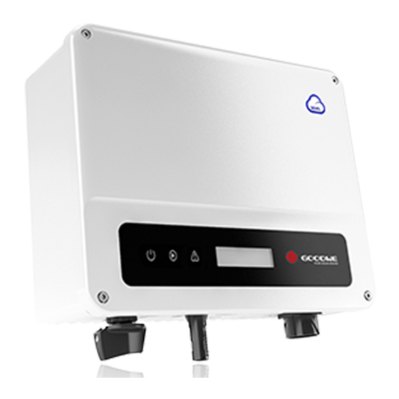
Page 4: Product Introduction
(Optional) To our inverter product, GOODWE provides standard manufacture warranty which comes with the 4. CT & DRED/Remote Shutdown product and prepaid warranty extension solution to our customer. You can find the details about /RS485 Port (Optional) the terms and solution from below linkage. -
Page 5: Package
3.2 Package The unit is thoroughly tested and strictly inspected before delivery. Damage may still occur during shipping. 1. Check the package for any visible damage upon receiving. Keep away Keep it clear Keep dry Rain Accmulated snow 2. Check the inner contents for damage after unpacking. from sunlight of snow 3. -
Page 6: Electrical Connection
4.3.1 Connection To The Grid (AC Side Connection) 1. When connecting the inverter make sure to adjust the voltage and the frequency in compliance with the grid regulations and the specifications of the GOODWE. Tighten screw clockwise Material (Annealed copper wire) 2. - Page 7 AC cable specification 7. For the XS series the minimum insulation resistance to the ground of the PV panels must exceed 16.7kΩ (R=500/30mA). There is risk of shock hazard if this minimum resistance requirement is not me. Grade Description Value There are four types of DC connectors, DEVALAN, MC4, AMPHENDL H4 and QC4.10 series.
-
Page 8: Communication Connection
Step 1 detailed instruction. Strip the wire insulation sheet of a suitable length with a wire stripper. The WiFi module installation of XS series are shown as below. L2 = L1 + (1~2mm) Step 2 Insert the stripped wire into the terminal and compress it tightly by crimping pliers. - Page 9 Put the cable through the connector and connect to the terminal. cation function is required. RS485 communication connection of XS series are shown as below. For single inverter connection Please connect RS485 cables to 'RS485-' port (3 or 7) and 'RS485+'...
- Page 10 DRED function is off by default. Start this function via SolarGo App if it's needed. Remote shutdown is only for Europe installations, in compliance with European safety require- ments. And Remote shutdown device is not provided by GOODWE. Remote shutdown function is off by default. Start this function via SolarGo App if it's needed.
-
Page 11: System Operation
There are 2 modes of button operation: Short press the button and long press the button. In compliance with the section 13.9 of IEC62109-2, the XS series inverter is equipped with an earth In all levels of menu, if no action is taken, the backlight of the LCD will switch off, the LCD will fault alarm. - Page 12 5.2.3 LCD Long Press Normal 50Hz Grid Default Pac = xxx W A schematic of the display screen is shown as below: Short Press E-Today =xxx .xx KWh Long Press Pac = xxx W Normal Short Press Pac=XXXX.XW E-Total =xxx .xx KWh Long Press Pac = xxx W Short Press...
- Page 13 • Short press the button to enter the "Ipc" menu which displays the PV current in "A". • Short Press the button to enter the "Vac" menu which displays the grid voltage in "V". Previous page • Short Press the button to once more to enter the "Iac" menu which display the grid current in "A". •...
- Page 14 "Set Protocol Display" menu. Long press the button to enter sub menu. The circulatory sub • Modify Password: menu including two protocols can be found. The protocol can be chosen by short pressing the Long press the button to enter password change menu. Short press to increase the number in button.
-
Page 15: Error Message
If sub test finishes and LCD displays "Test ***** Ok", inverter relay breaks off and reconnect to grid Short press the button until the LCD displays "Wi-Fi Reload", then long press the button until the automatically according to CEI 0-21 requirement. Then the next test starts. LCD displays "Wi-Fi Reloading�". - Page 16 5.6.3 QU Curve Mode PF Power Curve Mode Function Default value (Australia) Default value (New Zealand) Setting range QU curve mode can be modified by Calibrate communication, according to the set range to set PF curve mode enable or disable “0”or“1”...
-
Page 17: Troubleshooting
6 Troubleshooting Type of fault Troubleshooting If the Inverter is not able to work properly, please refer to the following instructions before Relay-Check Failure contacting your local service. If any problems arise, the red (FAULT) LED indicator on the front DCI Injection High panel will light up and the LCD screen will display relevant information. -
Page 18: Maintenace
8 Technical Parameters 7 Maintenace Regular maintenance of the inverter ensures its service life and optimal efficiency. Technical Data GW700-XS GW1000-XS GW1500-XS GW2000-XS Input Note: Disconnect the AC circuit breaker, then turn off the DC switch. Wait for 5 minutes to release Max. - Page 19 PV Reverse Polarity Protection Integrated Start-up Voltage (V) Anti-islanding Protection Integrated Nominal Input Voltage (V) AC Overcurrent Protection Integrated Max. Input Current per MPPT (A) 12.5 12.5 AC Short Circuit Protection Integrated Max. Short Circuit Current per MPPT (A) 15.6 15.6 AC Overvoltage Protection Integrated...
- Page 20 Relative Humidity 0~100% ℃ ( ) 2,500 3,000 3,000 3,300 Brazil) Max. Operating Altitude (m) 4000 Max Power at 40℃ (Including AC 2,500 3,000 3,000 3,300 Cooling Method Natural Convection ( ) l i z ) User Interface LED, LCD (Optional), WLAN+APP Nominal Output Voltage (V) 220/230 220/230...
- Page 21 Topology Non-isolated ℃ ( ) l i z ) 1000 1500 2000 Self-consumption at Night (W) <1 Max Power at 40℃ (Including AC Overload) (W) 1000 1500 2000 (Only for Brazil) Ingress Protection Rating IP65 Nominal Output Voltage (V) DC Connector MC4 (2.5~4mm²) Output Voltage Range (V) 154~288...
- Page 22 Dimension (W×H×D mm) 295×230×113 Max. Output Current (A) 14.3 14.3 Noise Emission (dB) <25 Max. Output Fault Current (Peak and Duration) 25@5ms 30@5ms 30@5ms (A/ms) Topology Non-isolated Inrush Current (Peak and Duration) (A/us) 50@2us 50@2us 50@2us Self-consumption at Night (W) <1 Nominal Output Current (A) 11.4/10.9...
-
Page 23: Power Off The Inverter
AC Connector plug and play connector Environmental Category 4K4H Moisture Location Category Definition Pollution Degree Level Moisture parameters Overvoltage Category DC II / AC III 4K4H Protective Class Temperature Range 0~+40℃ -33~+40℃ -20~+55℃ The Decisive Voltage Class (DVC) PV: C AC: C Com: A Humidity Range 5%~85% 15%~100%...
Need help?
Do you have a question about the XS Series and is the answer not in the manual?
Questions and answers
should the indicator/power light be continually flashing during the day?