
Subscribe to Our Youtube Channel
Related Manuals for Mean Well SHP-10K-HV Series


Summary of Contents for Mean Well SHP-10K-HV Series
- Page 1 SHP-10K-HV Series Installation manual Security Industrial Automate Telecom 10KW HVDC Power Supply 3φ3-wire wide input range High efficiency Intelligent...
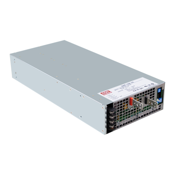
- Page 2 SHP-10K-HV is a 10KW 3ψ 3W input AC/DC power supply. This series operates for the wide range three phase AC input (3 phase 3 wire / 340~530VAC) neutral is not needed, and offers the models with DC outputs (55V/115V/230V/380V) that mostly demanded by various industries.
-
Page 3: Table Of Contents
Contents 1.Safety Guidelines 6.Communication Protocol PMBus Communication 2.Introduction Interface Model Encoding CAN Bus Communication Features Interface 2 3 . Specification 6 3 . Modbus Communication 2 4 . Derating curve Interface 2 5 . Mechanical specification Value range and tolerance 3.Installation &... -
Page 4: Safety Guidelines
1.Safety Guidelines 2.Introduction Model Encoding Risk of electrical shock and energy hazard, all failure should be examined by a qualified technician. Please do not remove the case form the power supply by SHP - yourself. Please do not change any component on the unit or make any kind of Communication protocol option modification on it. -
Page 5: Features
Features Specification 3φ3-wire without Neutral / 340~530VAC wide input range MODEL SHP-10K-55 SHP-10K-115 SHP-10K-230 SHP-10K-380 DC VOLTAGE (factory default) 55V 115V 230V 380V High efficiency up to 9 % CURRENT (factory default) 131A 43.5A 26.3A Water/ forced air cooling selectable RATED RANGE 0 ~ 150A 0 ~ 87A... -
Page 6: 4 . Derating Curve
erating curve SAFETY STANDARDS UL62368-1, CAN/CSA C22.2 No. 62368-1, TUV BS EN/EN62368-1, EAC TP TC 004 approved WITHSTAND VOLTAGE I/P-O/P:3.75KVAC I/P-FG:2KVAC O/P-FG:1.25KVAC ℃ ISOLATION RESISTANCE I/P-O/P, I/P-FG, O/P-FG:100M Ohms / 500VDC / 25 / 70% RH Blank Type Parameter Standard Test Level / Note Conducted BS EN/EN55032 (CISPR32) / EN55011 (CISPR11) -
Page 7: 5 . Mechanical Specification
2.5 Mechanical specification Forced-Air Cooling (Blank type) 431.75 94.75 39.25 for 55V 4-M4 L=5mm for other 45.9 50 55 60 (HORIZONTAL) CN86 CN53 DIP-SW 4-M4 L=5mm AMBIENT TEMPERATURE WITH 85CFM FAN*2 Air flow direction 94.75 4-M4 L=5mm for other for 55V 18 max. -
Page 8: Installation & Wiring
3.Installation & Wiring Water Cooling (L type) Mounting 3.1.1 Normal Mounting The B lank type is suggested mounting on horizontal surfaces. Horizontal mounting 3.1.2 Mounting on a Water Cooled Plate CN86 CN53 A.L type with a water cooled plate for heat dissipation, it is suggested 257.5 DIP-SW LED SVR... -
Page 9: Installation Notes
Installation Notes B.Recommended settings for cooling water operating parameters. Ambient temperature: 50℃ A.Before any installation or maintenance work, please disconnect your Inlet temperature: 5~15℃ system from the utility. Ensure that it cannot be re-connected Flow rate (minimum): 4~ 10LPM inadvertently. Humidity: 20~90% RH non-condensing B.Keep enough insulation distance between mounting screws and Pressure drop 6 psi (minimum), pressure inlet 80 psi (maximum) -
Page 10: Ac Power Connection
AC Power Connection Guidance of Additional Filter ◎ / △ 3φ3-wire 340VAC~530VAC A.Schematic SHP-10K LINE LOAD B Minimum insertion loss (In dB at 50 Ω system): Filter model FN3288 20 33 C35 R65 or equivalent Figure FREQ. MHz 0.01 0.05 0.10 0.15 0.50... -
Page 11: Panel And Led Indicator
4.Panel and LED Indicator 4.1.2 Pin Assignment of CN53 lank type 4.1.1 Panel Description AC input terminals DC output terminals -V(Signal) -V(Signal) DIP-SW1: Used for parallel control/PV/PC functions Function pins: They are used for control and monitoring functions. Please refer to 4.1.2 and 4.1.3. -
Page 12: L Type
4.2 L type Pin No. Function Description 4. .1 Panel Description The unit can turn the output ON/OFF by dry contact between AC input terminals Remote ON/OFF and +5-AUX.(Note) Remote Short (4.5 ~ 5.5V) : Power ON ; Open(0 ~ 0.5V) : Power OFF ; ON-OFF DC output terminals The maximum input voltage is 5.5V... - Page 13 4. .2 Pin Assignment of CN53 Pin No. Function Description The unit can turn the output ON/OFF by dry contact between Remote ON/OFF and +5-AUX.(Note) Remote Short (4.5 ~ 5.5V) : Power ON ; Open(0 ~ 0.5V) : Power OFF ; ON-OFF The maximum input voltage is 5.5V Auxiliary voltage output, 4.5~5.5V, referenced to GND-AUX...
-
Page 14: Operation
5.Operation 5.3.2 PV (Output Voltage Programming) A.Have the DIP switch position-3 set as Inrush Current Limiting 1 2 3 Built-in AC inrush current limiting circuit. ● Since the inrush current limiting circuit mainly consists of a NTC ● B.Connect output of the external DC source to PV+ and -V(signal) , as thermistor and a relay, inrush current will be much higher than the... -
Page 15: Output Current Adjustment
Iout 5.3.3 Communication Output voltage can be adjusted through communication interfaces: PMBus, CAN bus or Modbus. Please refer to chapter 6 for detailed Non-Linear information. Non-Linear Output Current Adjustment Output current can be adjusted via PC and communication interface. ● HORIZONTAL 5.4.1 PC(Output Current Programming) ℃... -
Page 16: Remote Control
Remote Control 5. . 5 2 SHP-10K has the built-in active current sharing function and can be The power supply can be turned ON-OFF by using the "Remote ● connected in parallel, up to 4 units, to provide higher output power as ON-OFF"... -
Page 17: Auxiliary Output
Auxiliary Output 6.Communication Protocol Built-in 12V/1A auxiliary output ● There are two means to control the unit, analog signals and digital ● communication. Analog is the default setting for the unit, signals including PV, PC and SVR can be used immediately once receiving the unit. The digital communication (PMBus, CAN bus or Modbus) is initially uncontrollable but readable. - Page 18 ◎Definition of Command BEh SYSTEM_CONFIG 6 1 2 PMBus Command List ◎The command list of the SHP-10K is shown in Table 6-2. It is Bit7 Bit6 Bit5 Bit4 Bit3 Bit2 Bit1 Bit0 compliant with the standard protocol of PMBus Rev. 1.1.For High byte detailed information, please refer to PMBus official website Low byte...
-
Page 19: Can Bus Communication
Bit 6 EEPER: EEPROM data access error Data Byte High Data Byte Low 0 EEPROM = data access normal 7 6 5 4 3 2 1 0 7 6 5 4 3 2 1 0 1 EEPROM = data access error Linear Data Format Data Bytes Y, N and the "real world"... - Page 20 Data filed bytes Table 6-4 Command Command Transaction # of data Description Code Name Type Bytes COMD low byte COMD high byte Data low byte Data high byte ON/OFF control Read: 0x0000 OPERATION ON: 01h/OFF: 00h Data filed bytes Output voltage set 0x0020 VOUT_SET (format: value, F=0.01)
- Page 21 Bit 7 HI_TEMP:Internal high temperature protection Command Command Transaction # of data Description Code Name Type Bytes 0=Internal temperature normal 1=Internal temperature abnormal System status 0x00C1 SYSTEM_STATUS System configuration 0x00C2 SYSTEM_CONFIG Note: Unsupported settings displays with "0" Note : The conversion of setting and reading values is defined as following: ◎MFR_ID_B0B5 ( 0x0080 ) is the first 6 codes of the manufacturer's name...
- Page 22 Bit 4:7 IOUT Factor:The Factor of DC current ◎MFR_DATE_B0B5 ( 0x0086 ) is manufacture date (ASCII) 0x = Output current relevant commands not supported MFR_DATE_B0B5 is 180101, meaning 2018/01/01 0x4=0.001 Byte 0 Byte 1 Byte 2 Byte 3 Byte 4 Byte 5 0x5=0.01 0x31...
- Page 23 ◎SYSTEM_CONFIG byte3: (0x00C2): Bit 0:3 IIN Factor:The Factor of AC input current Bit7 Bit6 Bit5 Bit4 Bit3 Bit2 Bit1 Bit0 0x = AC input current relevant commands not supported Low byte OPERATION_INIT CAN_CTRL 0x4=0.001 Bit 0 CAN_CTRL:CANBus communication control status 0x5=0.01 =...
-
Page 24: 3 . Modbus Communication
6 3 . Modbus Communication Interface 6.3.3 Additional Address Definition Additional address is the slave ID of the device. Each SHP-10K The device supports Modbus RTU with the master-salve principle. unit should have their unique and own device address to Users are able to read and write parameters of the device through communicate over the bus. - Page 25 6.3.5 Data Field and Command Lists Register Command Function # of data Description Data field provides additional information by the slave to address Name code Bytes complete the action specified by the function code(FC) in a Output voltage read value 0x0060 READ_VOUT 0x04...
- Page 26 ◎FAULT_STATUS (0x0040): ◎MFR_ID_B0B5 (0x0080 - 0x0082) is the first 6 codes of the Bit7 Bit6 Bit5 Bit4 Bit3 Bit2 Bit1 Bit0 manufacturer's name (ASCII); MFR_ID_B6B11(0x0083 - 0x0085) is the Low byte HI_TEMP OP_OFF AC_FAIL SHORT FAN FAIL last 6 codes of the manufacturer's name (ASCII) EX: manufacturer's name is MEANWELL →...
- Page 27 ◎SCALING_FACTOR (0x00C0): Byte 0 Byte 1 Byte 2 Byte 3 Byte 4 Byte 5 0xFE 0x69 0xFF 0xFF 0xFF 0xFF Bit7~Bit0 byte4~5 Reserved ◎MFR_DATE_B0B5 (0x0091 -0x0093) is manufacture date (ASCII ) Bit7 Bit6 Bit5 Bit4 Bit3 Bit2 Bit1 Bit0 EX: MFR_DATE_B0B5 is 180101 , meaning 2018/01/01 byte3...
- Page 28 ◎SYSTEM_STATUS byte1: (0x00C3): Bit 0:3 VIN Factor:The Factor of AC input voltage Bit7 Bit6 Bit5 Bit4 Bit3 Bit2 Bit1 Bit0 0x0=AC input relevant commands not supported INITIA- Low byte EEPER ADL_ON PFC OK DC_OK M S / LSTATE 0x4=0.001 0x5=0.01 Bit 0: M/S:parallel mode status 0x6=0.1 0=Current device is Slave...
- Page 29 Request: OPERATION_INIT:Pre-set value of power on operation command 0b00=Power OFF, pre-set 0x00(OFF) 0x80 0x04 0x0 6 0x2FC5 0b01=Power ON, pre-set0x01(ON) 0x80: Slave ID 0 0b10=Pre-set is previous set value 0x0 : Function code 4 (Read Analog Input Registers) 0b11=not used, reserved 0x0060: The Data Address of the first register requested 0x0001: he total number of registers requested ( read only 1 registers from 6.3.7 Communication Examples...
-
Page 30: Value Range And Tolerance
Value range and tolerance Note: READ_IOUT will display ZERO amp when output current is less than values (1)Display parameters in the table below. Model Display value range Tolerance Model Minimum readable READ_VIN 340~530V ±10V 1. A 5 ±1.5A 115V 0.87 ±0.87A 230V 0.46 ±0.46A READ_IIN... -
Page 31: Protections And Trouble
When AC voltage is too low, SHP-10K will enter protection mode to If you are unable to clarify the problem you are facing, please contact MEAN WELL or any of our distributors for repair service. prevent damaging itself. The supply will restore automatically when AC voltage is back to a normal range. -
Page 32: Warranty
※ MEAN WELL possesses the right to adjust the content of this manual. Please refer to the latest version of manual on our website. https://www.meanwell.com... - Page 33 N o . 2 8 , W u q u a n 3 r d R d . , W u g u D i s t . , N e w Ta i p e i C i t y 2 4 8 , Ta i w a n...
Need help?
Do you have a question about the SHP-10K-HV Series and is the answer not in the manual?
Questions and answers