
Subscribe to Our Youtube Channel
Related Manuals for Measurement Computing USB-5200 Series


Summary of Contents for Measurement Computing USB-5200 Series
- Page 1 USB-5203 Multi-sensor Measurement and Data Logger User's Guide Document Revision 14A January 2015 © Copyright 2015...
- Page 2 Other product and company names mentioned herein are trademarks or trade names of their respective companies. © 2015 Measurement Computing Corporation. All rights reserved. No part of this publication may be reproduced, stored in a retrieval system, or transmitted, in any form by any means, electronic, mechanical, by photocopying, recording, or otherwise without the prior written permission of Measurement Computing Corporation.
-
Page 3: Table Of Contents
Table of Contents Preface About this User’s Guide ........................5 What you will learn from this user's guide ......................5 Conventions in this user's guide ......................... 5 Where to find more information ......................... 5 Chapter 1 Introducing the USB-5203 ........................6 Logging data with the USB-5203 ............................. - Page 4 USB-5203 User's Guide Screw terminals................................18 USB connector .................................19 LED ....................................19 ® CompactFlash memory card slot ............................19 Data logging button .................................20 External power supply ............................21 Disconnecting the USB-5203 from the computer ..................... 21 Transferring binary data after a logging session ....................21 Converting binary data after a logging session ....................
-
Page 5: Preface
Preface About this User’s Guide What you will learn from this user's guide This user's guide describes the Measurement Computing USB-5203 data acquisition device and lists device specifications. Conventions in this user's guide For more information Text presented in a box signifies additional information related to the subject matter. -
Page 6: Introducing The Usb-5203
Chapter 1 Introducing the USB-5203 The USB-5203 provides eight differential input channels that are software-programmable for different sensor categories including thermocouple, RTDs, thermistors, and semiconductor sensors. Eight independent, TTL-compatible digital I/O channels are provided to monitor TTL-level inputs, communicate with external devices, and to generate alarms. The digital I/O channels are software- programmable for input or output. -
Page 7: Functional Block Diagram
USB-5203 User's Guide Introducing the USB-5203 You can specify the number of seconds between samples. You can begin logging data at power up, when you press the data logging button, or at a specific date and time. Data is stored on the memory card in binary files. After logging measurements, you can transfer the files to your computer. -
Page 8: Installing The Usb-5203
Refer to the MCC DAQ Quick Start for instructions on installing the software on the MCC DAQ CD. Refer to the device product page on the Measurement Computing website for information about the included and optional software supported by the USB-5203. -
Page 9: Configuring The Hardware
Calibrating the hardware Factory calibration The Measurement Computing Manufacturing Test department performs the initial factory calibration. Return the device to Measurement Computing Corporation when calibration is required. The recommended calibration interval is one year. Field-calibration The USB-5203 supports field-calibration with InstaCal. Calibrate the device whenever the ambient temperature changes by more than ±10 °C from the last self-calibration. -
Page 10: Chapter 3 Sensor Connections
Chapter 3 Sensor Connections The USB-5203 supports the following temperature sensor types: Thermocouple – types J, K, R, S, T, N, E, and B Resistance temperature detectors (RTDs) – 2, 3, or 4-wire measurement modes of 100 Ω platinum RTDs. ... -
Page 11: Current Excitation Output Terminals (±I1 To ±I4)
USB-5203 User's Guide Sensor Connections Do not connect two different sensor categories to the same channel pair The USB-5203 provides a 24 bit A/D converter for each channel pair. Each channel pair can monitor one sensor category. To monitor a sensor from a different category, connect the sensor to a different channel pair (input terminals). -
Page 12: Wiring Configuration
USB-5203 User's Guide Sensor Connections Wiring configuration Connect the thermocouple to the USB-5203 using a differential configuration, as shown in Figure 3. Figure 3. Typical thermocouple connection The USB-5203 pins are isolated from earth ground, so connecting thermocouple sensors to voltages referenced to earth ground is permissible as long as the isolation between the GND pins (9, 19, 28, 38) and earth ground is maintained. -
Page 13: Two-Wire Configuration
USB-5203 User's Guide Sensor Connections Two-wire configuration The easiest way to connect an RTD sensor or thermistor to the USB-5203 is with a two-wire configuration, since it requires the fewest connections to the sensor. With this method, the two wires that provide the RTD sensor with its excitation current also measure the voltage across the sensor. -
Page 14: Three-Wire Configuration
USB-5203 User's Guide Sensor Connections Three-wire configuration A three-wire configuration compensates for lead-wire resistance by using a single-voltage sense connection. With a three-wire configuration, you can connect only one sensor per channel pair. A three-wire measurement configuration is shown in Figure 6. Figure 6. -
Page 15: Semiconductor Sensor Measurements
USB-5203 User's Guide Sensor Connections Figure 8. Four-wire, single RTD or thermistor sensor measurement configuration A four-wire, two-sensor measurement configuration is shown in Figure 9. Figure 9. Four-wire, two RTD or thermistor sensors measurement configuration When configured for two-wire mode, both sensors must be connected to obtain proper measurements. Semiconductor sensor measurements Semiconductor sensors are suitable over a range of approximately -40 °C to 125 °C, where an accuracy of ±2 °C is adequate. -
Page 16: Digital I/O Connections
USB-5203 User's Guide Sensor Connections Digital I/O connections You can connect up to eight digital I/O lines to the screw terminals labeled DIO0 DIO7 . All digital I/O lines are pulled up to +5V with a 47 kΩ resistor (default). You can request the factory to configure the resistor for pull-down to ground if desired. -
Page 17: Chapter 4 Functional Details
Chapter 4 Functional Details Thermocouple measurements A thermocouple consists of two dissimilar metals that are joined together at one end. When the junction of the metals is heated or cooled, a voltage is produced that correlates to temperature. The USB-5203 hardware level-shifts the thermocouple’s output voltage into the A/D’s common mode input range by applying +2.5 V to the thermocouple’s low side at the C#L input. -
Page 18: Rtd And Thermistor Measurements
USB-5203 User's Guide Functional Details RTD and thermistor measurements RTDs and thermistors are resistive devices that require an excitation current to produce a voltage drop that can be measured differentially across the sensor. The USB-5203 measures the sensor resistance by forcing a known excitation current through the sensor and then measuring (differentially) the voltage across the sensor to determine its resistance. -
Page 19: Usb Connector
USB-5203 User's Guide Functional Details USB connector When not logging data, connect the USB cable to a USB port on your computer or to an external USB hub that is connected to your computer. When connected to an active USB bus, the USB connector provides +5 V power and communication. -
Page 20: Data Logging Button
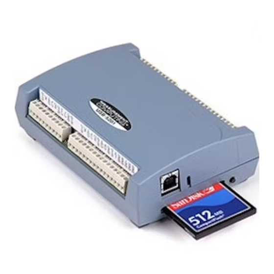
USB-5203 User's Guide Functional Details Calculating the logging time for a memory card Use the following formula to calculate the approximate amount of logging time in seconds that one of the supported memory card allows. The USB-5203 supports 512 MB , 1 GB, and 2 GB CompactFlash memory cards. -
Page 21: External Power Supply
USB-5203 User's Guide Functional Details External power supply The external power supply is a 2.5 W USB power adapter used to power the device during data logging operations. Disconnecting the USB-5203 from the computer You don't need to shut down your computer to disconnect the USB-5203. Refer to the instructions below when disconnecting the USB-5203 from your computer's USB port. -
Page 22: Chapter 5 Specifications
Chapter 5 Specifications All specifications are subject to change without notice. Typical for 25 °C unless otherwise specified. Specifications in italic text are guaranteed by design. Analog input Table 1. Generic analog input specifications Parameter Conditions Specification A/D converters Four dual 24-bit, Sigma-Delta type Number of channels 8 differential Input isolation... -
Page 23: Compatible Sensors
USB-5203 User's Guide Specifications Table 2. Channel configuration specifications Sensor Category Conditions Max number of sensors (all channels configured alike) Disabled (Note 1) Thermocouple J, K, S, R, B, E, T, or N 8 differential channels Semiconductor sensor 8 differential channels RTD and thermistor 2-wire input configuration with a single sensor per channel pair 4 differential channels... -
Page 24: Semiconductor Sensor Measurement Accuracy
USB-5203 User's Guide Specifications Table 4. Thermocouple accuracy specifications, including CJC measurement error Sensor Type Maximum error (°C) Typical error (°C) Temperature range (°C) ±1.499 ±0.507 –210 to 0 ±0.643 ±0.312 0 to 1200 ±1.761 ±0.538 –210 to 0 ±0.691 ±0.345 0 to 1372 ±2.491... -
Page 25: Thermistor Measurement Accuracy
USB-5203 User's Guide Specifications Thermistor measurement accuracy The error shown in Table 7 below does not include errors of the sensor itself. The sensor linearization is performed using a Steinhart-Hart linearization algorithm. These specs are for one year while operating the device between 15 °C and 35 °C. -
Page 26: Digital Input/Output
USB-5203 User's Guide Specifications Table 9. Throughput rate specifications Number of Input Maximum Throughput Channels 2 Samples/second 2 S/s on each channel, 4 S/s total 2 S/s on each channel, 6 S/s total 2 S/s on each channel, 8 S/s total 2 S/s on each channel, 10 S/s total 2 S/s on each channel, 12 S/s total 2 S/s on each channel, 14 S/s total... -
Page 27: Temperature Alarms
USB-5203 User's Guide Specifications Temperature alarms Table 11. Temperature alarm specifications Parameter Specification Number of alarms 8 (one per digital I/O line) Alarm functionality Each alarm controls its associated digital I/O line as an alarm output. The input to each alarm may be any of the analog temperature input channels. -
Page 28: Data Logging
USB-5203 User's Guide Specifications Data Logging Table 14. Data logging specifications Parameter Specification Standalone power supply USB power adapter 2.5 watt USB adapter with interchangeable plugs (Includes plug for USA) Memory card type CompactFlash Supplied memory card 512 MB CompactFlash card Memory card host access USB Mass Storage Device (MSD) File systems supported... -
Page 29: Usb +5V Voltage
USB-5203 User's Guide Specifications USB +5V voltage Table 16. USB +5 V voltage specifications Parameter Specification USB +5 V (VBUS) input voltage 4.75 V min to 5.25 V max range Power Table 17. Power specifications Parameter Conditions Specification Connected to USB Supply current USB enumeration <100 mA... -
Page 30: Current Excitation Outputs (Ix+)
USB-5203 User's Guide Specifications Current excitation outputs (Ix+) The device has four current excitation outputs, with I1+/I1– dedicated to the CH0/CH1 analog inputs, I2+/I2– dedicated to CH2/CH3, I3+/I3– dedicated to CH4/CH5, and I4+/I4– dedicated to CH6/CH7. The excitation output currents should always be used in this dedicated configuration. The current excitation outputs are automatically configured based on the sensor (thermistor or RTD) selected. - Page 31 USB-5203 User's Guide Specifications Table 23. Screw terminal pinout Signal Name Pin Description Signal Name Pin Description CH0/CH1 current excitation source I4– CH6/CH7 current excitation return No connection Ground CH0 sensor input (+) CH7 sensor input (–) CH0 sensor input (–) CH7 sensor input (+) 4W01 CH0/CH1 4-wire, 2 sensor common...
-
Page 32: Declaration Of Conformity
Norton, MA 02766 Category: Electrical equipment for measurement, control and laboratory use. Measurement Computing Corporation declares under sole responsibility that the product USB-5203 to which this declaration relates is in conformity with the relevant provisions of the following standards or other... - Page 33 Measurement Computing Corporation 10 Commerce Way Suite 1008 Norton, Massachusetts 02766 (508) 946-5100 Fax: (508) 946-9500 E-mail: info@mccdaq.com www.mccdaq.com...
Need help?
Do you have a question about the USB-5200 Series and is the answer not in the manual?
Questions and answers