
Related Manuals for Measurement Computing USB-PDISO8/40


Summary of Contents for Measurement Computing USB-PDISO8/40
- Page 1 USB-PDISO8/40 USB-based Isolated Input and Relay Output User's Guide June 2021. Rev 7 © Measurement Computing Corporation...
- Page 2 Other product and company names mentioned herein are trademarks or trade names of their respective companies. © 2021 Measurement Computing Corporation. All rights reserved. No part of this publication may be reproduced, stored in a retrieval system, or transmitted, in any form by any means, electronic, mechanical, by photocopying, recording, or otherwise without the prior written permission of Measurement Computing Corporation.
-
Page 3: Table Of Contents
Differential isolated digital inputs ............................10 Cabling ....................................12 Field wiring and signal termination accessories ........................12 Daisy chaining additional devices to the USB-PDISO8/40 ................13 Power limitations using multiple USB-PDISO8/40 devices ................. 13 Supply current ..................................13 Voltage drop ..................................14 Relay contact protection circuit for inductive loads ...................... -
Page 4: Preface
Preface About this User's Guide What you will learn from this user's guide This user's guide describes the Measurement Computing USB-PDISO8/40 data acquisition device and lists device specifications. Conventions in this user's guide For more information Text presented in a box signifies additional information related to the subject matter. -
Page 5: Introducing The Usb-Pdiso8/40
USB port in a daisy-chain configuration.* Rugged enclosure that you can mount on a DIN rail or on a bench The USB-PDISO8/40 is powered by an external 9 V, 1.67 A regulated power supply that is shipped with the device. Functional block diagram USB-PDISO8/40 functions are illustrated in the block diagram shown here. -
Page 6: Installing The Usb-Pdiso8/40
USB-PDISO8/40. Install the software before you install your device The driver needed to run the USB-PDISO8/40 is installed with the software. Therefore, you need to install the software package you plan to use before you install the hardware. - Page 7 USB-PDISO8/40 User's Guide Installing the USB-PDISO8/40 If your system does not detect the USB-PDISO8/40 If a USB device not recognized message displays when you connect the USB-PDISO8/40, complete the following steps: Unplug the USB cable from the USB-PDISO8/40. Unplug the external power cord from the connector on the enclosure.
-
Page 8: Functional Details
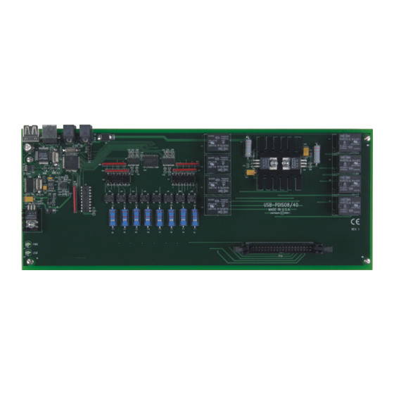
Chapter 3 Functional Details The USB-PDISO8/40 provides SPDT relay control and isolated inputs in a plug-and-play package. All I/O connections are made to a 40-pin connector (see Main connector and pin out on page 9). Components The USB-PDISO8/40 has the following internal components, as shown in Figure 2. -
Page 9: Power In Connector
USB-PDISO8/40 User's Guide Functional Details POWER IN connector The USB-PDISO8/40 requires between 6.5 V and 12.5 V of external power. An external power connection is required to activate the relays and to run tests in InstaCal. To supply external power, connect the... -
Page 10: Relay Contacts
• Relay 6 Normally Closed contact Relay contacts Connect external devices to the relay contacts using the 40-pin connector on the USB-PDISO8/40. Each relay has a normally closed (NC), common (C), and normally open (NO) contact. Form C relay output A schematic for Form C relay contacts is shown in Figure 3. - Page 11 InstaCal. Install»Configure Figure 4. USB-PDISO8/40 single-channel configuration Figure 5 shows a schematic of a simple connection from a +9 V battery to the relay 4 connector pins. When the relay is energized, relay 4 NO connects the battery voltage to input 4 terminal B.
-
Page 12: Cabling
Figure 9. C40-37M-x cable Field wiring and signal termination accessories Use the following screw terminal boards to terminate field signals and route them into the USB-PDISO8/40 using the cables above. CIO-MINI40 – 40-pin screw terminal board. CIO-MINI37 – 37-pin screw terminal board. -
Page 13: Daisy Chaining Additional Devices To The Usb-Pdiso8/40
Use the supplied cable or an equivalent full-speed cable when daisy chaining to other MCC USB devices. The device already connected to the computer is referred to as the host device. The additional device(s) that you want to daisy chain to the host USB-PDISO8/40 is referred to as the slave device. -
Page 14: Voltage Drop
6.5 VDC is provided to the last device in the chain. Always provide a separate power supply when the USB-PDISO8/40 is the last device in the chain. Relay contact protection circuit for inductive loads When you connect an inductive load to a relay, energy stored in the inductive load can induce a large voltage surge when you switch the relay. -
Page 15: Specifications
Chapter 4 Specifications All specifications are subject to change without notice. Typical for 25 °C unless otherwise specified. Specifications in italic text are guaranteed by design. Relay specifications Table 1. Relay output specifications Number Contact configuration 8 FORM C (SPDT) NO, NC and Common available at connector Contact rating 6 A @ 240 VAC or 28 VDC resistive (see Main connector on page 17) Contact resistance... -
Page 16: Power
200 mA typ, 230 mA max Note 1: The USB-PDISO8/40 monitors the external +9 V power supply voltage with a voltage supervisory circuit. If this power supply exceeds its specified limit, the PWR LED turns off, indicating a power fault condition. -
Page 17: Mechanical
USB-PDISO8/40 User's Guide Specifications Mechanical Table 6. Mechanical specifications Board dimensions (L × W × H) 304.3 × 121.9 × 17.8 mm (12.0 × 4.8 × 0.7 in.) Enclosure dimensions (L × W × H) 342.9 × 125.7 × 58.9 mm (13.5 × 4.95 × 2.32 in.) Environmental Table 7. -
Page 18: P14
USB-PDISO8/40 User's Guide Specifications Signal Name Signal Name Input 7 terminal A Input 7 terminal B Input 6 terminal A Input 6 terminal B Input 5 terminal A Input 5 terminal B Input 4 terminal A Input 4 terminal B... -
Page 19: Declaration Of Conformity
May 3, 2016, Norton, Massachusetts USA Test Report Number: EMI4813.07 Measurement Computing Corporation declares under sole responsibility that the product USB-PDISO8/40, Product Revision C* or later Complies with the essential requirements of the following applicable European Directives: Electromagnetic Compatibility (EMC) Directive 2014/30/EU... -
Page 20: Declaration Of Conformity, Legacy Hardware
Category: Electrical equipment for measurement, control and laboratory use. Measurement Computing Corporation declares under sole responsibility that the product USB-PDISO8/40, Product Revisions up to B* to which this declaration relates is in conformity with the relevant provisions of the following standards or other... - Page 21 Measurement Computing Corporation NI Hungary Kft 10 Commerce Way H-4031 Debrecen, Hátar út 1/A, Hungary Norton, Massachusetts 02766 Phone: +36 (52) 515400 (508) 946-5100 Fax: +36 (52) 515414 Fax: (508) 946-9500 http://hungary.ni.com/debrecen E-mail: info@mccdaq.com www.mccdaq.com...
Need help?
Do you have a question about the USB-PDISO8/40 and is the answer not in the manual?
Questions and answers