
Related Manuals for Measurement Computing USB-TC-AI


Summary of Contents for Measurement Computing USB-TC-AI
- Page 1 Distributed by MicroDAQ.com, Ltd. www.MicroDAQ.com (603) 746-5524 USB-TC-AI Thermocouple and Voltage Measurement User's Guide Document Revision 4 March 2013 © Copyright 2013...
-
Page 2: Distributed By Microdaq.com, Ltd. Www.microdaq.com (603)
© 2013 Measurement Computing Corporation. All rights reserved. No part of this publication may be reproduced, stored in a retrieval system, or transmitted, in any form by any means, electronic, mechanical, by photocopying, recording, or otherwise without the prior written permission of Measurement Computing Corporation. -
Page 3: Table Of Contents
Where to find more information ......................... 5 Chapter 1 Introducing the USB-TC-AI ........................6 Functional block diagram ........................... 6 Connecting a USB-TC-AI to your computer is easy ..................7 Chapter 2 Installing the USB-TC-AI ........................8 What comes with your shipment? ........................8 Hardware .................................. - Page 4 Distributed by MicroDAQ.com, Ltd. www.MicroDAQ.com (603) 746-5524 USB-TC-AI User's Guide Accuracy ................................17 Thermocouple measurement accuracy: T0x to T3x ......................17 Absolute accuracy: V0x-V3x ............................18 Settling time: V0x-V3x ..............................18 Analog input calibration ........................... 19 Throughput rate ..............................19 Digital I/O ................................. 19 Temperature alarms ............................
-
Page 5: Preface
(603) 746-5524 Preface About this User’s Guide What you will learn from this user's guide This user's guide describes the Measurement Computing USB-TC-AI data acquisition device and lists device specifications. Conventions in this user's guide For more information Text presented in a box signifies additional information related to the subject matter. -
Page 6: Introducing The Usb-Tc-Ai
An open thermocouple detection feature lets you detect a broken thermocouple. An on-board microprocessor automatically linearizes the measurement data. The USB-TC-AI is a standalone plug-and-play module which draws power from the USB cable. No external power supply is required. All configurable options are software programmable. -
Page 7: Connecting A Usb-Tc-Ai To Your Computer Is Easy
HID because it is a standard, and its performance delivers full control and maximizes data transfer rates for your USB-TC-AI. No third-party device driver is required. The USB-TC-AI is plug-and-play. There are no jumpers to position, DIP switches to set, or interrupts to configure. ... -
Page 8: Installing The Usb-Tc-Ai
Installing the hardware To connect the USB-TC-AI to your system, turn your computer on, and connect the USB cable to a USB port on your computer or to an external USB hub that is connected to your computer. The USB cable provides power and communication to the USB-TC-AI. -
Page 9: Configuring The Hardware
A/D inputs. Warm up Allow the USB-TC-AI to warm up for 30 minutes after powering up before taking measurements. This warm up time minimizes thermal drift and achieves the specified rated accuracy of measurements. -
Page 10: Signal I/O Connections
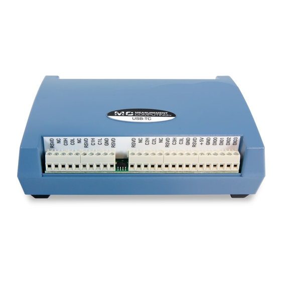
Screw terminal pinout The USB-TC-AI has four rows of screw terminals — two rows on the top edge of the housing, and two rows on the bottom edge. Each row has 26 connections. Between screw terminals 10 and 11 is the integrated CJC sensor used for thermocouple measurements. -
Page 11: Thermocouple Input
The counter can count events at frequencies of up to 1 MHz. Caution! All ground pins on the USB-TC-AI (pins 9, 19, 22, 27, 30, 33, 36, 39, 49) are common and are isolated from earth ground. If a connection is made to earth ground when using digital I/O and conductive thermocouples, the thermocouples are no longer isolated. -
Page 12: Digital I/O Connections
Figure 4. Schematic showing switch detection by digital channel DIO0 All ground pins on the USB-TC-AI (pins 9, 19, 22, 27, 30, 33, 36, 39, 49) are isolated from earth ground. If a connection is made to earth ground when using digital I/O and conductive thermocouples, the thermocouples are no longer isolated. -
Page 13: Chapter 4 Functional Details
+2.5 V to the thermocouple’s low side at the C#L input. Always connect thermocouple sensors to the USB-TC-AI in a floating fashion. Do not attempt to connect the thermocouple low side C#L to GND or to a ground referencing resistor. -
Page 14: External Components
(603) 746-5524 USB-TC-AI User's Guide Functional Details External components The USB-TC-AI has the following external components, as shown in Figure 5. Screw terminal pins 1 to 26 LEDs: Activity (top) and Power (bottom) Screw terminal pins 27 to 52 USB connector Figure 5.External component locations... -
Page 15: Chapter 5 Specifications
Distributed by MicroDAQ.com, Ltd. www.MicroDAQ.com (603) 746-5524 Chapter 5 Specifications Typical for 25 °C unless otherwise specified. All specifications apply to all temperature and voltage input channels unless otherwise specified. Specifications in italic text are guaranteed by design. Analog input Table 1. -
Page 16: Channel Configurations
V0x to V3x Single-ended 4 single-ended channels Internally, the USB-TC-AI has four, dual-channel, fully differential A/Ds providing a total of eight Note 1: input channels. Note 2: When connecting differential inputs to floating input sources, you must provide a DC return path from each differential input to ground. -
Page 17: Accuracy
These specs are for one year, or 3000 operating hours, whichever comes first, and for operation of the USB-TC-AI between 15 °C and 35 °C. There is a CJC sensor on the temperature sensor input side of the module. The accuracy listed above assumes the screw terminals are at the same temperature as the CJC sensor. -
Page 18: Absolute Accuracy: V0X-V3X
1.69 17.98 Table 7 summarizes the noise performance for the USB-TC-AI. Noise distribution is determined by gathering 1000 samples with inputs tied to ground at the user connector. Samples are gathered at the maximum specified sample rate of 2 S/s. -
Page 19: Analog Input Calibration
3.8 V min (IOH = -2.5 mA max) All ground pins on the USB-TC-AI (pins 9, 19, 22, 27, 30, 33, 36, 39, 49) are common and are Note 12: isolated from earth ground. If a connection is made to earth ground when using digital I/O and conductive thermocouples, the thermocouples are no longer isolated. -
Page 20: Temperature Alarms
Distributed by MicroDAQ.com, Ltd. www.MicroDAQ.com (603) 746-5524 USB-TC-AI User's Guide Specifications Temperature alarms Table 12. Temperature alarm specifications Parameter Specification Number of alarms 8 (one per digital I/O line) Alarm functionality Each alarm controls its associated digital I/O line as an alarm output. The input to each alarm may be any of the analog temperature input channels. -
Page 21: Microcontroller
(terminal block pin 21) Isolation Measurement system to PC 500 VDC min Note 14: This is the total current requirement for the USB-TC-AI which includes up to 10 mA for the status LED. USB specifications Table 18. USB specifications Parameter... -
Page 22: Mechanical
Distributed by MicroDAQ.com, Ltd. www.MicroDAQ.com (603) 746-5524 USB-TC-AI User's Guide Specifications Mechanical Table 20. Mechanical specifications Parameter Specification Dimensions (L × W × H) 128.52 x 88.39 × 35.56 mm (5.06 × 3.48 × 1.43 ft) User connection length 3 m (9.84 ft) max Screw terminal connector Table 21. -
Page 23: Declaration Of Conformity
Norton, MA 02766 Category: Electrical equipment for measurement, control and laboratory use. Measurement Computing Corporation declares under sole responsibility that the product USB-TC-AI EU EMC Directive 89/336/EEC: Electromagnetic Compatibility, EN 61326 (1997) Amendment 1 (1998) Emissions: Group 1, Class A ... - Page 24 Distributed by MicroDAQ.com, Ltd. www.MicroDAQ.com (603) 746-5524 Measurement Computing Corporation 10 Commerce Way Suite 1008 Norton, Massachusetts 02766 (508) 946-5100 Fax: (508) 946-9500 E-mail: info@mccdaq.com www.mccdaq.com...
Need help?
Do you have a question about the USB-TC-AI and is the answer not in the manual?
Questions and answers