Table of Contents
Advertisement
Quick Links
Advertisement
Table of Contents

Subscribe to Our Youtube Channel
Related Manuals for Measurement Computing USB-1096HFS


Summary of Contents for Measurement Computing USB-1096HFS
- Page 2 USB-1096HFS Measurement Advantage™ brand USB-based Digital I/O User's Guide Document Revision 3, March, 2005 © Copyright 2005, Measurement Computing Corporation...
- Page 3 Measurement Computing. Thank you for choosing a Measurement Computing product—and congratulations! You own the finest, and you can now enjoy the protection of the most comprehensive warranties and unmatched phone tech support. It’s the embodiment of our two missions: To offer the highest-quality, computer-based data acquisition, control, and GPIB hardware and software available—...
- Page 4 Information furnished by Measurement Computing Corporation is believed to be accurate and reliable. However, no responsibility is assumed by Measurement Computing Corporation neither for its use; nor for any infringements of patents or other rights of third parties, which may result from its use. No license is granted by implication or otherwise under any patent or copyrights of Measurement Computing Corporation.
-
Page 5: Table Of Contents
Introducing the USB-1096HFS......................1-1 Overview: USB-1096HFS features ........................ 1-1 USB-1096HFS block diagram........................1-2 Software features ............................1-2 Connecting a USB-1096HFS to your computer is easy.................. 1-3 Chapter 2 Installing the USB-1096HFS ......................2-1 What comes with your USB-1096HFS shipment? ..................2-1 Hardware .................................. - Page 6 USB-1096HFS User's Guide Ribbon connector and pin outs ........................4-4 P1 ....................................4-5 P2 ....................................4-5 P3 ....................................4-6 P4 ....................................4-6...
-
Page 7: About This User's Guide
What you will learn from this user's guide This user's guide explains how to install, configure, and use the USB-1096HFS so that you get the most out of its digital I/O features. This user's guide also refers you to related documents available on our web site, and to technical support resources. -
Page 9: Introducing The Usb-1096Hfs
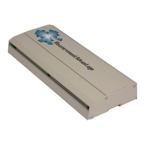
The USB-1096HFS also provides 50-pin mass termination connectors. For OEM's who wish to use the mass term connectors, the enclosure needs to be removed. The USB-1096HFS is shipped in a rugged metal enclosure that you can mount on a DIN rail or on a bench (see Figure 1-1). -
Page 10: Usb-1096Hfs Block Diagram
USB-1096HFS User's Guide Introducing the USB-1096HFS USB-1096HFS block diagram USB-1096HFS functions are illustrated in the block diagram shown here. HIGH DRIVE FOURTHPORT 9V nominal External FOURTHPORTA Power FOURTHPORTB FOURTHPORTCH FOURTHPORTCL Power Monitor HIGH DRIVE THIRDPORT THIRDPORTA Power THIRDPORTB Regulator THIRDPORTCH... -
Page 11: Connecting A Usb-1096Hfs To Your Computer Is Easy
The USB-1096HFS is plug-and-play. There are no jumpers to position, dual in-line package (DIP) switches to set, or interrupts to configure. You can connect the USB-1096HFS before or after you install the software, and without powering down your computer first. -
Page 13: Installing The Usb-1096Hfs
Chapter 2 Installing the USB-1096HFS What comes with your USB-1096HFS shipment? As you unpack your USB-1096HFS, make sure that the following components are included. Hardware USB-1096HFS External power supply and cord (CB-PWR-9V3A) – 9 volt, 3 amp DC power supply... -
Page 14: Documentation
USB 1.1 port or USB 2.0 port on your computer. Connecting the external power supply Power to the USB-1096HFS is provided with the +9 V external power supply (CB-PWR-9V3A). You must connect the external power supply before connecting the USB cable to the USB-1096HFS and your computer. -
Page 15: Connecting The Usb-1096Hfs To Your System
Connecting the USB-1096HFS to your system To connect the USB-1096HFS to your system, connect the USB cable to a USB port on your computer or to an external USB hub that is connected to your computer. The USB cable provides communication to the USB-1096HFS. - Page 16 3. Plug the external power cord back into the connector. POWER IN 4. Plug the USB cable back into the USB-1096HFS. Your system should now properly detect the USB-1096HFS hardware. Contact technical support if your system still does not detect the USB-1096HFS.
-
Page 17: Functional Details
Chapter 3 Functional Details Internal components These USB-1096HFS components are shown in Figure 3-1. Two (2) USB connectors Two (2) external power connectors USB LED PWR LED 12 pull-up/pull-down resistors Four (4) screw terminal banks (Port 1 through Port 4) -
Page 18: Usb In Connector
Measurement Advantage products from POWER OUT a single external power supply. When running at full load, the USB-1096HFS draws 2.6 A from the supply. When using the USB-1096HFS under full load conditions, do not daisy chain power to another Measurement Advantage board. -
Page 19: Screw Terminal Wiring
USB-1096HFS User's Guide Functional Details Screw terminal wiring The USB-1096HFS has four rows of screw terminals labeled through . Each row has 26 Port 1 Port 4 connections. The screw terminals provide the following connections: 96 digital I/O terminals (... - Page 20 USB-1096HFS User's Guide Functional Details Table 3-2 for the signal name associated with each board label. Caution! Keep the length of stripped wire at a minimum to avoid a short to the enclosure! When connecting your field wiring to the screw terminals, use the strip gage on the terminal strip,...
-
Page 21: Digital I/O Terminals (Firstporta Bit 0 To Fourthportc Bit 7)
USB-1096HFS User's Guide Functional Details Table 3-2. Board labels and associated signal names Board label Signal name Board label Signal name Port 1 P1A0 (FIRSTPORTA Bit 0) Port 3 P3A0 (THIRDPORTA Bit 0) P1A1 (FIRSTPORTA Bit 1) P3A1 (THIRDPORTA Bit 1) -
Page 22: Power Terminals
When configured for input, you can use the USB-1096HFS digital I/O terminals to detect the state of any TTL level input. Figure 3-2 shows the USB-1096HFS wired to detect the state of a switch. When you set the switch to the position, FIRSTPORTA Bit 0 reads TRUE (1). -
Page 23: Ground Terminals
To daisy-chain two or more USB-1096HFS modules, follow the steps below. This procedure assumes you already have one USB-1096HFS connected to a computer and to the external power source. The USB-1096HFS already connected to the computer is referred to as the connected module. The USB- 1096HFS you want to daisy-chain to the connected module is referred to as the new module. -
Page 24: Power Limitations Using Multiple Usb-1096Hfs Devices
9 VDC nominal, 3.0 A external power supply. Supply current Running one USB-1096HFS at full load draws 2.6 A from the 3A supply. When using the USB-1096HFS under full load conditions, you cannot daisy chain additional Measurement Advantage boards unless you supply external power to each board in the chain. -
Page 25: Specifications
Chapter 4 Specifications Typical for 25 °C unless otherwise specified. Specifications in italic text are guaranteed by design. Digital input / output Table 4-1. Digital I/O specifications Output 74ABT244A Input 74ACT373 Configuration 8 banks of 8, 8 banks of 4, programmable by bank as input or output Number of I/O Output high 2.0 volts min @ -24 mA... -
Page 26: Counter Section
USB-1096HFS User's Guide Specifications The daisy chain power output option allows multiple Measurement Advantage boards to be Note 1: powered from a single external power source in a daisy chain fashion. The voltage drop between the input of one module and its daisy chain output is 0.5 V maximum. -
Page 27: Data Transfer Rates
USB-1096HFS User's Guide Specifications Data transfer rates Table 4-7. Data transfer rate specifications Digital I/O transfer rates (software System dependent, 33 to 1000 port reads/writes or single bit reads/writes per paced) second typ. Counter/timer read/write rates Counter Read – System dependent, 33 to 1000 reads per second. - Page 28 USB-1096HFS User's Guide Specifications Table 4-10. Screw terminal pin out Board label Signal name Board label Signal name Port 1 P1A0 (FIRSTPORTA Bit 0) Port 3 P3A0 (THIRDPORTA Bit 0) P1A1 (FIRSTPORTA Bit 1) P3A1 (THIRDPORTA Bit 1) P1A2 (FIRSTPORTA Bit 2)
- Page 29 USB-1096HFS User's Guide Specifications Table 4-12. P1 pin out Signal Name Signal Name FIRSTPORTC Bit 7 FIRSTPORTC Bit 6 FIRSTPORTC Bit 5 FIRSTPORTC Bit 4 FIRSTPORTC Bit 3 FIRSTPORTC Bit 2 FIRSTPORTC Bit 1 FIRSTPORTC Bit 0 FIRSTPORTB Bit 7...
- Page 30 USB-1096HFS User's Guide Specifications Table 4-14. P3 pin out Signal Name Signal Name THIRDPORTC Bit 7 THIRDPORTC Bit 6 THIRDPORTC Bit 5 THIRDPORTC Bit 4 THIRDPORTC Bit 3 THIRDPORTC Bit 2 THIRDPORTC Bit 1 THIRDPORTC Bit 0 THIRDPORTB Bit 7...
- Page 31 Middleboro, MA 02346 Category: Electrical equipment for measurement, control and laboratory use. Measurement Computing Corporation declares under sole responsibility that the product USB-1096HFS to which this declaration relates is in conformity with the relevant provisions of the following standards or other documents:...
- Page 32 Measurement Computing Corporation 16 Commerce Boulevard, Middleboro, Massachusetts 02346 (508) 946-5100 Fax: (508) 946-9500 E-mail: info@mccdaq.com www.mccdaq.com...
Need help?
Do you have a question about the USB-1096HFS and is the answer not in the manual?
Questions and answers