
Related Manuals for Measurement Computing TC-32


Summary of Contents for Measurement Computing TC-32
- Page 1 Distributed by MicroDAQ.com, Ltd. www.MicroDAQ.com (603) 746-5524 TC-32 32-Channel Thermocouple Input USB/Ethernet DAQ Device User's Guide Document Revision 2 November 2015 © Copyright 2015...
-
Page 2: Distributed By Microdaq.com, Ltd. Www.microdaq.com (603)
© 2015 Measurement Computing Corporation. All rights reserved. No part of this publication may be reproduced, stored in a retrieval system, or transmitted, in any form by any means, electronic, mechanical, by photocopying, recording, or otherwise without the prior written permission of Measurement Computing Corporation. -
Page 3: Table Of Contents
Installing the hardware ............................8 Installing on USB................................8 Installing on Ethernet ................................ 8 IP address settings ................................9 Setting up the TC-32 for communication across networks ................. 9 Calibrating the hardware........................... 10 Factory calibration ................................10 Field calibration ................................10 Updating firmware ............................10 Restoring factory default network settings ....................... - Page 4 Distributed by MicroDAQ.com, Ltd. www.MicroDAQ.com (603) 746-5524 TC-32 User's Guide Microcontroller ..............................21 Power ................................21 USB .................................. 22 Network ................................22 Ethernet connection .................................22 Network interface ................................22 Network factory default settings ............................23 Network security ................................23 LED displays and the factory reset button ......................23 Environment ..............................
-
Page 5: Preface
Italic text is used for the names of manuals and help topic titles, and to emphasize a word or phrase. Where to find more information Additional information about TC-32 hardware is available on our website at www.mccdaq.com. You can also contact Measurement Computing Corporation with specific questions. -
Page 6: Chapter 1 Introducing The Tc-32
MAC address. xxxxxx USB interface The TC-32 is a USB 2.0 full-speed device that is compatible with USB 3.0 ports. The device is also compatible with USB 1.1 ports. 40-pin ribbon cable for the EXPANSION connector is included with the TC-32-EXP. -
Page 7: Functional Block Diagram
Distributed by MicroDAQ.com, Ltd. www.MicroDAQ.com (603) 746-5524 TC-32 User's Guide Introducing the TC-32 Functional block diagram Device functions are illustrated in the block diagram shown here: Figure 1. TC-32 functional block diagram... -
Page 8: Chapter 2 Installing The Tc-32
TC-32 device, and plug the AC adapter into an electrical outlet. Power LED turns on when 5 V power is supplied to the TC-32. If the voltage supply is less than 4.0 V or more than 5.75 V, the POWER LED does not turn on. -
Page 9: Ip Address Settings
TC-32 and the device to which it is connected DHCP Only Enables configuration by a DHCP server if one is available. The TC-32 is assigned an IP address shortly after it is powered up and attached to the network. Link Local Only The TC-32 is assigned a link-local IP address by the Windows PC or other host that supports link-local addressing. -
Page 10: Calibrating The Hardware
Each ADC (two ADCs per device) is measured at three points and a linear correction is calculated. When prompted, enter the voltmeter reading to a precision of three decimal places. MCC strongly recommends that you warm up the TC-32 for at least 20 minutes prior to performing field calibration. -
Page 11: Chapter 3 Functional Details
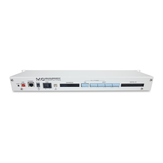
Distributed by MicroDAQ.com, Ltd. www.MicroDAQ.com (603) 746-5524 Chapter 3 Functional Details External components TC-32 front panel components are shown in Figure 2. TC input channels 0 through 31 (32 mini-jack connectors) ALARM POWER OPEN TC ACTIVITY Figure 2. TC-32 front panel components TC-32 rear panel components are shown in Figure 3. - Page 12 Figure 4. TC-32 common mode voltage connections example Cold junction compensation (CJC) Each TC input on the TC-32 has a high-resolution CJC sensor. When you connect the thermocouple sensor leads to the sensor input channel, the dissimilar metals at the TC-32 terminal blocks produce an additional thermocouple junction.
-
Page 13: Digital I/O
Open-thermocouple detection (OTD) The TC-32 is equipped with OTD for all analog input channel. With OTD, any open-circuit condition at the TC sensor is detected by the software. An open channel is detected by the use of a pull up and pull down resistors on the thermocouple inputs. -
Page 14: Led Indicators
The TC-32 has four LEDs that indicate the power, communication, alarm, and open TC status POWER LED POWER LED turns on when you plug the power adapter into the TC-32. If a Flash LED command is sent from an application, the Power LED blinks five times. -
Page 15: Expansion Connector
Provides a connection point (#6-32 screw) for chassis ground. Connect this to an external grounding source. If the TC-32 is connected by USB or by a shielded Ethernet cable to grounded equipment, connecting to an external grounding source is not needed since the USB/shielded Ethernet connection already grounds the TC-32 and a connected TC-32-EXP. -
Page 16: Mechanical Drawings
Distributed by MicroDAQ.com, Ltd. www.MicroDAQ.com (603) 746-5524 TC-32 User's Guide Functional Details Mechanical drawings Figure 6. Enclosure dimensions - rear Figure 5. Enclosure dimensions - front... - Page 17 Distributed by MicroDAQ.com, Ltd. www.MicroDAQ.com (603) 746-5524 TC-32 User's Guide Functional Details Figure 7. Enclosure dimensions – side Figure 8. Circuit board dimensions...
-
Page 18: Chapter 4 Specifications
Distributed by MicroDAQ.com, Ltd. www.MicroDAQ.com (603) 746-5524 Chapter 4 Specifications All specifications are subject to change without notice. Typical for 25 °C unless otherwise specified. Specifications in italic text are guaranteed by design. Thermocouple input Table 1. Generic analog input specifications Parameter Condition Specification... -
Page 19: Channel Configuration
Distributed by MicroDAQ.com, Ltd. www.MicroDAQ.com (603) 746-5524 TC-32 User's Guide Specifications When thermocouple sensors are connected to different common mode voltages, the channels with Note 2: floating thermocouples sensors will be biased to approximately the average value of the applied common mode voltages. -
Page 20: Digital Input/Output
Distributed by MicroDAQ.com, Ltd. www.MicroDAQ.com (603) 746-5524 TC-32 User's Guide Specifications Sensor Sensor Accuracy Error Accuracy Error Accuracy Error Accuracy Error Type Temperature Maximum (°C), Typical (°C), Maximum (°C), Typical (°C), (°C) 15°C to 35°C 15°C to 35°C 0°C to 45°C 0°C to 45°C... -
Page 21: Temperature Alarms
Distributed by MicroDAQ.com, Ltd. www.MicroDAQ.com (603) 746-5524 TC-32 User's Guide Specifications Temperature alarms Table 7. Temperature alarm specifications Parameter Specification Number of alarms 32, shared with digital output Each alarm controls its associated digital output line as an alarm output. When an... -
Page 22: Usb
Network ports used TCP:54211 (commands) Network IP configuration DHCP + link-local, DHCP, static, link-local TC-32-xxxxxx, where xxxxxx are the lower 6 digits of the device MAC Network name address By NBNS (responds to b-node broadcasts, therefore only available on the local... -
Page 23: Network Factory Default Settings
ACTIVITY LEDs blink in firmware upgrade mode. On when there is a valid connection and blinks when a command is sent to the ACTIVITY LED TC-32. Both the POWER and ACTIVITY LEDs blink in firmware upgrade mode. ALARM LED Indicates that an alarm condition is met. -
Page 24: Signal I/O Connectors
Distributed by MicroDAQ.com, Ltd. www.MicroDAQ.com (603) 746-5524 TC-32 User's Guide Specifications Signal I/O connectors Table 19. Connector specifications Parameter Specification User accessible I/O connectors Thermocouple inputs, digital I/O connector, expansion connector, chassis ground (excluding USB and Ethernet) Thermocouple connector type... - Page 25 Isolated Analog GND RSVD Reserved AGND Isolated Analog GND EXP_DETECT EXP detection AGND Isolated Analog GND Note 8: Power supplies (+12 VA, +5 VA, 3.3 VA) located at connector J34 are intended for use with the TC-32-EXP expansion device only.
-
Page 26: Declaration Of Conformity
Date and Place of Issue: October 15, 2015, Norton, Massachusetts USA Test Report Number: EMI6774.15 Measurement Computing Corporation declares under sole responsibility that the product(s) TC-32 Complies with the essential requirements of the following applicable European Directives: Electromagnetic Compatibility (EMC) Directive 2004/108/EC... - Page 27 Distributed by MicroDAQ.com, Ltd. www.MicroDAQ.com (603) 746-5524 Measurement Computing Corporation NI Hungary Kft 10 Commerce Way H-4031 Debrecen, Hátar út 1/A, Hungary Norton, Massachusetts 02766 Phone: +36 (52) 515400 (508) 946-5100 Fax: +36 (52) 515414 Fax: (508) 946-9500 http://hungary.ni.com/debrecen E-mail: info@mccdaq.com...
Need help?
Do you have a question about the TC-32 and is the answer not in the manual?
Questions and answers