
Subscribe to Our Youtube Channel
Related Manuals for Measurement Computing USB-5200 Series


Summary of Contents for Measurement Computing USB-5200 Series
- Page 1 USB-5201 Thermocouple Measurement and Data Logger User's Guide Document Revision 11A January 2015 © Copyright 2015...
- Page 2 Other product and company names mentioned herein are trademarks or trade names of their respective companies. © 2015 Measurement Computing Corporation. All rights reserved. No part of this publication may be reproduced, stored in a retrieval system, or transmitted, in any form by any means, electronic, mechanical, by photocopying, recording, or otherwise without the prior written permission of Measurement Computing Corporation.
-
Page 3: Table Of Contents
Table of Contents Preface About this Manual ..........................5 Conventions ................................ 5 Where to find more information ......................... 5 Chapter 1 Introducing the USB-5201 ........................6 Logging data with the USB-5201 ............................. 6 Functional block diagram ........................... 7 Chapter 2 Installing the USB-5201 ........................ - Page 4 USB-5201 User's Guide Chapter 5 Specifications ............................18 Analog input ..............................18 Channel configuration ............................18 Accuracy ................................19 Thermocouple measurement accuracy ..........................19 Throughput rate to PC ............................20 Digital I/O ................................. 20 Temperature alarms ............................21 Memory ................................21 Microcontroller ..............................
-
Page 5: Preface
Preface About this Manual This document describes the Measurement Computing USB-5201 data acquisition device and lists device specifications. Conventions For more information Text presented in a box signifies additional information related to the subject matter. Caution! Shaded caution statements present information to help you avoid injuring yourself and others, damaging your hardware, or losing your data. -
Page 6: Introducing The Usb-5201
Chapter 1 Introducing the USB-5201 The USB-5201 provides eight differential thermocouple input channels and two integrated cold junction compensation (CJC) sensors. You can take measurements from type J, K, R, S, T, N, E, and B thermocouples. An open thermocouple detection feature lets you detect a broken thermocouple. An on-board microprocessor automatically linearizes the measurement data. -
Page 7: Functional Block Diagram
USB-5201 User's Guide Introducing the USB-5201 Functional block diagram USB-5201 functions are illustrated in the block diagram shown here. Figure 1. Functional block diagram... -
Page 8: Installing The Usb-5201
Refer to the MCC DAQ Quick Start for instructions on installing the software on the MCC DAQ CD. Refer to the device product page on the Measurement Computing website for information about the included and optional software supported by the USB-5201. -
Page 9: Configuring Data Logging Options
Calibrating the hardware Factory calibration The Measurement Computing Manufacturing Test department performs the initial factory calibration. Return the device to Measurement Computing Corporation when calibration is required. The recommended calibration interval is one year. Field-calibration The USB-5201 supports field-calibration with InstaCal. Calibrate the device whenever the ambient temperature changes by more than ±10 °C from the last self-calibration. -
Page 10: Chapter 3 Sensor Connections
Chapter 3 Sensor Connections The USB-5201 supports type types J, K, R, S, T, N, E, and B thermocouples. Thermocouple selection The thermocouple type you select depends on your application needs. Review the temperature ranges and accuracies of each type to determine which is best suited for your application. Screw terminal pinout The USB-5201 has four rows of screw terminals –... -
Page 11: Digital I/O
USB-5201 User's Guide Sensor Connections Digital I/O You can connect up to eight digital I/O lines to the screw terminals labeled . Each terminal is DIO0 DIO7 software-configurable for input or output. If a digital bit is set up as an alarm, the bit is configured for output on power-up, and assumes the state defined by the alarm configuration. -
Page 12: Digital I/O Connections
USB-5201 User's Guide Sensor Connections Digital I/O connections You can connect up to eight digital I/O lines to the screw terminals labeled . You can configure DIO0 DIO7 each digital bit for either input or output. All digital I/O lines are pulled up to +5 V with a 47 kΩ resistor (default). -
Page 13: Chapter 4 Functional Details
Chapter 4 Functional Details Thermocouple measurements A thermocouple consists of two dissimilar metals that are joined together at one end. When the junction of the metals is heated or cooled, a voltage is produced that correlates to temperature. The USB-5201 hardware level-shifts the thermocouple’s output voltage into the A/D’s common mode input range by applying +2.5 V to the thermocouple’s low side at the C#L input. -
Page 14: External Components
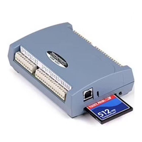
USB-5201 User's Guide Functional Details External components The USB-5201 has the following external components, as shown in Figure 5. Screw terminals USB connector CompactFlash slot with memory card Screw terminal pins 1 to 26 Data logging button Screw terminal pins 27 to 52 CompactFlash memory card slot (with card) USB connector... -
Page 15: Compactflash Memory Card Slot
USB-5201 User's Guide Functional Details LED function when the USB-5201 is connected to an active USB port LED Illumination Indication Steady green The USB-5201 is connected to a computer or external USB hub. Blinks continuously Data is being transferred. Upon connection, the LED should flash a few times and then remain lit (indicates a successful installation). -
Page 16: Data Logging Button
USB-5201 User's Guide Functional Details The following table provides examples of logging one channel and eight channels of temperature readings at the max logging rate of 1 S/s to a 512 MB memory card with DIO, timestamp, and CJC sensor logging enabled: Memory card DIO enabled Number of... -
Page 17: Transferring Binary Data After A Logging Session
USB-5201 User's Guide Functional Details Transferring binary data after a logging session Data is stored on the memory card in binary files. After logging measurements, you can transfer the files to your computer by reconnecting the USB-5201 to a USB port on your computer or by removing the CompactFlash card from the USB-5201 and using a card reader connected to your computer. -
Page 18: Chapter 5 Specifications
Chapter 5 Specifications All specifications are subject to change without notice. Typical for 25 °C unless otherwise specified. Specifications in italic text are guaranteed by design. Analog input Table 1. Generic analog input specifications Parameter Conditions Specification A/D converters Four dual 24-bit, Sigma-Delta type Number of channels 8 differential Input isolation... -
Page 19: Accuracy
USB-5201 User's Guide Specifications Accuracy Thermocouple specifications include linearization, cold-junction compensation and system noise. These specs are for one year, or 3000 operating hours, whichever comes first and for operation of the device between 15 °C and 35 °C. For measurements outside this range, add ±0.5 °C to the maximum error shown. There are CJC sensors on each side of the device. -
Page 20: Throughput Rate To Pc
USB-5201 User's Guide Specifications Throughput rate to PC The analog inputs are configured to run continuously. Each channel is sampled twice per second. The maximum latency between when a sample is acquired and the temperature data is provided by the USB unit is approximately 0.5 seconds. -
Page 21: Temperature Alarms
USB-5201 User's Guide Specifications Temperature alarms Table 6. Temperature alarm specifications Parameter Specification Number of alarms 8 (one per digital I/O line) Alarm functionality Each alarm controls its associated digital I/O line as an alarm output. The input to each alarm may be any of the analog temperature input channels. -
Page 22: Data Logging
USB-5201 User's Guide Specifications Data logging Table 9. Data logging specifications Parameter Specification Standalone power USB power adapter supply 2.5 watt USB adapter with interchangeable plugs (includes plug for USA) Memory card type CompactFlash Supplied memory card 512 MB CompactFlash card Memory card host USB Mass Storage Device (MSD) access... -
Page 23: Real-Time Clock
USB-5201 User's Guide Specifications Real-time clock Table 10. Real-time clock specifications Parameter Specification Battery backup CR-2032 lithium coin cell, replaceable Accuracy ±1 minute per month USB +5V voltage Table 11. USB +5 V voltage specifications Parameter Conditions Specification USB +5 V (VBUS) input voltage range 4.75 V min to 5.25 V max Power Table 12. -
Page 24: Usb Specifications
USB-5201 User's Guide Specifications USB specifications Table 13. USB specifications Parameter Specification USB device type USB 2.0 (full-speed) Device compatibility USB 1.1, USB 2.0 Self-powered, 500 mA consumption max USB cable type A-B cable, UL type AWM 2725 or equivalent. (min 24 AWG VBUS/GND, min 28 AWG D+/D–) USB cable length 3 meters (9.84 ft) max... - Page 25 USB-5201 User's Guide Specifications Table 17. Screw terminal pinout Signal Name Pin Description Signal Name Pin Description RSVD Reserved, do not use RSVD Reserved, do not use No connection Ground CH0 sensor input (+) CH7 sensor input (–) CH0 sensor input (–) CH7 sensor input (+) No connection RSVD...
-
Page 26: Declaration Of Conformity
Norton, MA 02766 Category: Electrical equipment for measurement, control and laboratory use. Measurement Computing Corporation declares under sole responsibility that the product USB-5201 to which this declaration relates is in conformity with the relevant provisions of the following standards or other... - Page 27 Measurement Computing Corporation 10 Commerce Way Suite 1008 Norton, Massachusetts 02766 (508) 946-5100 Fax: (508) 946-9500 E-mail: info@mccdaq.com www.mccdaq.com...
Need help?
Do you have a question about the USB-5200 Series and is the answer not in the manual?
Questions and answers