Table of Contents
Advertisement
Quick Links
Advertisement
Table of Contents

Related Manuals for easyRAID S4-FWTT


Summary of Contents for easyRAID S4-FWTT
- Page 1 S4-FWTT IEEE 1394 & USB 2.0 Disk Array System User Manual Version 1.1...
- Page 3 S4-FWTT IEEE 1394 & USB 2.0 Disk Array System User Manual...
- Page 5 Important Safety Instructions, Care and Handling Before starting, take a few minutes to read this manual. Read all of these instructions and save this manual for later reference. Protect the disk array system from extremely high or low temperatures. Let the disk array system warm (or cool) to room temperature before using it.
- Page 6 The appliance must be grounded. The disk array system is equipped with a 3-wire grounded type of power cord. This power cord will only fit into a grounded type of power outlet. If an extension cord or a power center is used with the disk array system, make sure that the total current con- sumption of all products plugged into the wall outlet does not exceed the ampere rating.
-
Page 7: P P R R E E F F A A Ce Ce E E
Preface Notice Product features and specifications described in this manual are subject to change without notice. The manufacturer shall not be liable for any damage, or for the loss of information resulting from the performance or use of the information contained herein. Trademarks This manual has been checked for accuracy, but no guarantee is given that the contents are correct. -
Page 8: Regulatory Information
User’s Manual Regulatory information For Europe This equipment is in conformity with the EMC directive. Federal Communications Commission (FCC) Statement This equipment has been tested and found to comply with the limits for a Class B digital device, pursuant to part 15 of the FCC Rules. Those limits are designed to provide reasonable protection against harmful interference in a residential installation. - Page 9 Preface UL Listed This equipment meets UL's safety requirements. CCC certificate This equipment is in conformity with the CCC S&E requirement.
-
Page 10: Intended User
User’s Manual About this manual Intended user This manual is designed and written for users of the subsystem. This is an entry level product suitable for most users. Organization of the manual This manual consists of the following sections: Chapter 1: Introduction provides an overview of the as well as details of key features and a list of specifications. -
Page 11: Using This Manual
Preface Using this manual This guide contains all the information you need to set up and start using your subsystem and to monitor its performance in real time. The setup process will follow these steps: Prepare: Familiarize yourself with the features and capabilities of (Chapter 1) Decide whether to set up a RAID 0, 0+1, 5 or 5+spare array (Chapter 2) -
Page 12: Guide To Conventions
User’s Manual Guide to Conventions Important information that users should be aware of is indicated with the following icons: This icon indicates the existence of a potential hazard that could result in personal injury, damage to your equipment or loss of data if the safety instruction is not observed. -
Page 13: Table Of Contents
Contents E ..................1 ........................1 OTICE ......................1 RADEMARKS ..................2 EGULATORY INFORMATION Intended user.....................4 Organization of the manual ................4 ....................5 SING THIS MANUAL ..................6 UIDE TO ONVENTIONS S ..............I CHAPTER 1.................1-1 N ................1-1 ......................1-1 VERVIEW ......................1-2 EY FEATURES Hot Spare .......................1-2 Automatic drive rebuilding ................1-2 Hard drive hot swapping ................1-2 Multiple host interface support ..............1-2... -
Page 14: T T A A B B L L E E O O F F C C O O N N T T E E N N T T S S
User’s Manual CHAPTER 3 ................3-1 M ..........3-1 ................3-1 AMILIARIZING YOURSELF WITH Overview ....................... 3-1 Front view ..................... 3-2 Rear view ...................... 3-3 Host connection ports: IEEE 1394 and USB interface version..... 3-3 ..................3-5 OADING DRIVES INTO CHAPTER 4 ................4-1 Y ............4-1 ................ - Page 15 Contents RAID and disk status messages..............C-2 RAID level Setting and Total RAID Capacity:..........C-2 Disk information: Vendor, model # (for example: Western Digital Caviar 7200rpm 120G).....................C-3 Disk information: mode, Capacity ..............C-3 Error and failure messages................C-3 Where the speed of failed fan is 100 rpm............C-6 Disk rebuilding messages ................C-6 Time setting....................C-7 APPENDIX D ................D-1...
-
Page 17: Chapter 1
Chapter 1 – Introduction This chapter introduces the features and capabilities of subsystem. You will find: A full introduction to your subsystem Details of key features A list of the product specifications Overview Congratulations on your selection of the subsystem. The subsystem is a high-performance and extremely flexible RAID subsystem. -
Page 18: Key Features
User’s Manual Key features The subsystem supports the following features Automatic on-line rebuilding Drives are hot swappable Supports RAID levels 0, 0+1 and 5 Optional hot spare setup for RAID 5 (5+spare) Hot swappable fan Supports four Serial ATA hard drives Requires no driver Audible alarm on drive failure &... - Page 19 Chapter 1 – Introduction IEEE 1394A/B (also known as I. Link and FireWire) USB 2.0 Auto disk shut down when over heat The will shut down disks automatically when temperature is over 55 C to prevent the damage of DISK and DATA loss. This manual contains the information necessary to set up each of the two available hardware configurations of the subsystem .
-
Page 20: Specifications
User’s Manual Specifications Available host intefaces and transfer speeds Firewire 400/800, IEEE 1394 A/B (50/100MBps) High-speed USB2.0 480MBps (60MBps) Disk Interface Support Four SATA1 1.5Gb disk interfaces and compatible with SATA2 3Gb disks RAID Function Support Hardware RAID level 0, 5, 0+1, 5 + spare by switch setting Hot swappable disk Automatic on-line rebuilding Subsystem Function Support... -
Page 21: Mechanical, Environmental And Safety Specifications
Chapter 1 – Introduction Mechanical, Environmental and Safety Specifications Dimensions: 152.8 x 206.4 x 286.5 (mm) Host Connectors (depending on hardware configuration): Two 9-pin 1394B with power connectors or one USB2.0 connector Interface Connectors: One RS-232 connector Operation temperature: 0 ~ 35℃ Operation humidity: 5 ~ 95 %, non-condensing Storage humidity: 5%~95% RH, Non-condensing 200 W power supply... -
Page 23: Chapter 2
Chapter 2 – Before you begin This chapter includes all the information you need to prepare for installation and to decide which RAID level to use. You will find: A checklist of what should be in the product package A full introduction to and comparison of RAID levels 0, 0+1 and 5 Important notices on the safe operation and installation of Making sure you have everything... - Page 24 User’s Manual The subsystem is available in two hardware configurations with the following host interfaces: Firewire 400/800, IEEE 1394 A/B (50/100MBps) High-speed USB2.0 480MBps (60MBps) Package content for the two versions differ as indicated on the following page. The following cables: Power cable IEEE1394a to 1394b cable (Combo PKG only)
-
Page 25: What Else You Need
Chapter 2 – Before you begin What else you need In order to setup a working system, the following user-supplied items are required: Host computer system with IEEE 1394 or USB interface (IEEE 1394 and USB host interface version) Four disk drives For non-proprietary accessories, such as cables, etc., ask your vendor to recommend compatible and reliable brands. -
Page 26: Raid 0
User’s Manual RAID 0 RAID 0 links each drive in the array as one huge drive. Storage capacity is determined by the smallest drive in the array. That capacity is then applied to format all other drives in the array. If using a 40 GB, 50GB, 60 GB, and 70 GB drive in a RAID 0 array, your system will see one huge drive of 160 GB (40 GB×4). -
Page 27: Raid 0+1
Chapter 2 – Before you begin RAID 0+1 RAID 0+1 combines mirroring and striping functions on a minimum of four hard disks. Mirroring provides full redundancy and protects data in case of multiple drive failure (providing that data on one of each mirrored pair of drives is intact). RAID 0+1: Combination of mirroring and striping Characteristics: This configuration provides optimal speed and reliability. -
Page 28: Raid 5 And Raid 5+Hot Spare
User’s Manual RAID 5 and RAID 5+hot spare RAID 5 uses a mathematical expression that compares data from three drives and calculates a fourth piece of data called “parity” which is saved on a fourth drive. Should one of the drives fail, parity data can be used to rebuild the failed data. Under RAID 5, parity data is stored across all drives in the array. - Page 29 Chapter 2 – Before you begin The diagram below represents the writing of data on a RAID 5 array composed of four DISKS connected to the controller. Parity blocks are represented by the letter P. The diagram below represents the writing of data on a RAID 5+hot spare array composed of four DISKS connected to the controller.
-
Page 30: Pre-Installation Notices
User’s Manual Pre-installation notices Before starting any kind of hardware installation, please ensure that all power switches have been turned off and all power cords disconnected to prevent personal injury and damage to the hardware. To avoid overheating, should be installed in a well-ventilated area and in such a way that sufficient airflow is maintained across the controller chips. -
Page 31: Familiarizing Yourself With
Chapter 3 – Setting up the subsystem This chapter gives an overview of the and explains how to: Remove the drive carriers from the controller box Load hard drives into the drive carriers Install the drive carriers in Familiarizing yourself with The subsystem is available in one hardware configurations with the following host interfaces: IEEE 1394A/B and USB 2.0... -
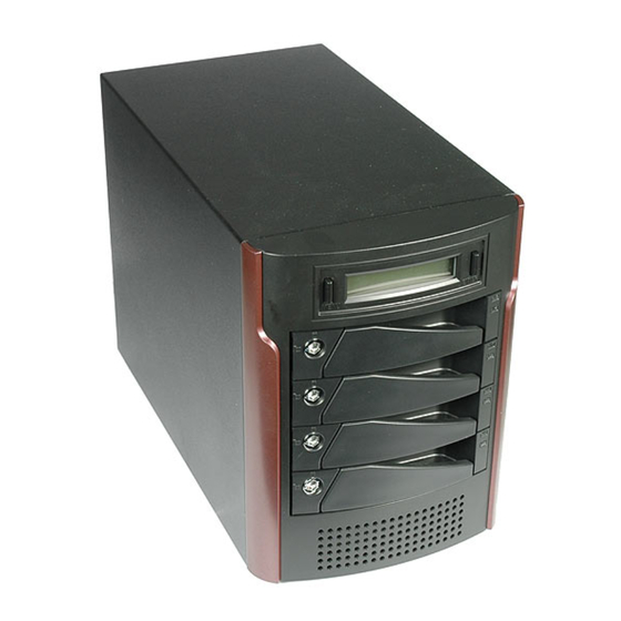
Page 32: Front View
User’s Manual Front view Drive carriers Each drive carrier can hold a one-inch high 3.5-inch form factor SATA disk drive. LCD Display The LCD displays status and configuration information for the subsystem and arrays. A full list of LCD display messages is given in Appendix C. -
Page 33: Rear View
Chapter 3 – Setting up the subsystem Rear view Power switch The power switch is the main on/off switch of the subsystem. Fan vent The fan vent should be kept unobstructed. RAID level selector The RAID level selector consists of two switches which together are used to set the RAID level. - Page 34 User’s Manual The USB port cannot be used when either of the IEEE 1394 ports is in use. 2 of IEEE 1394 port are for daisy chain to connect another IEEE1394 device. Not for connecting to 2 host at mean time for access. -3-4-...
-
Page 35: Loading Drives Into
Chapter 3 – Setting up the subsystem Loading drives into We recommend that you use one of the following hard disk brands: Fujitsu, IBM, Maxtor, Quantum, Seagate, or Western Digital. All four hard disks should be configured as Single Master. The subsystem should be fitted with four hard disk drives. - Page 36 User’s Manual 4. Slide the loaded disk drive carrier into the Controller Box and push flat the carrier handle to lock the carrier in position. -3-6-...
-
Page 37: Chapter 4
Chapter 4 – Setting up an array This chapter explains how to: Set RAID level on the controller box Create an array Remove and replace drives from an array Connect to a host computer Set the time and date on Array creation flowchart Setting up an array on is simple. -
Page 38: Setting Raid Level
User’s Manual Setting RAID level RAID level is set using the RAID level selector on the rear panel of the subsystem. The RAID level selector consists of two switches. The four possible combinations of switch position correspond to the four available RAID settings: 0, 0+1, 5 and 5+spare. - Page 39 Chapter 4 – Setting up an array The subsystem must be switched off to change RAID level. To change RAID level: Power off Set the new RAID level using the RAID level selector Remove all four disks Power on Install the four disks to start RAID initialization Changing RAID level may lead to the loss of all data on the array.
-
Page 40: Setting Raid 0
User’s Manual Setting RAID 0 1. Ensure is turned off 2. Move both selector switches 1 and 2 to ON as shown. Setting RAID 0+1 1. Ensure is turned off. 2. Move selector switch 1 to ON and 2 to OFF as shown Setting RAID 5 1. -
Page 41: Creating An Array
Chapter 4 – Setting up an array Creating an array To create (initialize) an array: 1. Ensure that the RAID level selectors are correctly positioned for the desired RAID level. 2. Connect a power cable. 3. Turn on the power switch. 4. - Page 42 User’s Manual The RAID capacity determined on the RAID level and the capacity of drives you installed in , for an example: If configuring as R5 and install 4 drives each of them are 10 GB, 20 GB, 30 GB, 40 GB to create an array then the total RAID capacity will be 30 If a red disk status indicator shows, check to make sure the appropriate drive is: Locked Installed correctly...
- Page 43 Chapter 4 – Setting up an array A full list of LCD display messages is given in Appendix C If system power is turned off midway through array initialization, the process will continue from its point of interruption when power returns. In a RAID 5+spare array, the disk in the TOP drive carrier is the hot spare initially.
-
Page 44: Removing / Replacing A Drive
User’s Manual Removing / replacing a drive What if a disk fails? If a disk drive fails, the disk status indicator of the disk carrier will light red and the alarm will sound. When this happens, you should replace the failed disk. The failure or removal of a single drive in a RAID5 array will not lead to failure of the array. -
Page 45: Removing A Drive
Chapter 4 – Setting up an array Removing a drive 1. Pull the drive carrier handle. 2. Slide the drive carrier out of the subsystem. 3. Remove four screws from the tray and lift out the disk drive. -4-9-... -
Page 46: Connecting To A Host Computer
User’s Manual Connecting to a host computer Once the array is initialized, you can connect to a host computer. The RAID cannot be recognized by Operating System before initialization complete. IEEE 1394 and USB host interface version The IEEE 1394 ports support IEEE 1394A which enables transmission speeds up to 400 Mbps and IEEE 1394b which enables transmission speeds up to 800 Mbps. - Page 47 Chapter 4 – Setting up an array The USB port cannot be used at the same time as either of the IEEE 1394 port. 2 of IEEE 1394 port are for daisy chain to connect another IEEE1394 device, not for connecting to 2 host at mean time for access. To connect to the host: 1.
-
Page 48: Setting The Display Time & Date
User’s Manual Setting the Display Time & Date Press down the right hand (Enter) button for over five seconds to enter or change the time and date displayed on the display. When you release the button, the date and time setting screen will show: 1. -
Page 49: Chapter 5
Chapter 5 – Partitioning the array This chapter explains how to partition the array in Windows , Linux and Mac OS X operating systems. Partitioning the array - Windows The array must be partitioned before it can be used. To do this on a Windows operating system: 1. - Page 50 User’s Manual 6. Right click on the disk representing the array and select Create Partition. Follow the wizard to create one or more partitions on the array. 7. When you have completed creating a partition, the array will appear as a disk in the disk management section of the Computer Management dialog box.
-
Page 51: Partitioning The Array - Linux
Chapter 5 – Partitioning the array Partitioning the array - Linux The array must be partitioned before it can be used. To do this on a Linux operating system: 1. Establish the array and connect to the host computer following the instructions in the preceding chapter. - Page 52 User’s Manual 6. Enter the command to add a partition (in the example given, the command is “n.”) 7. Enter the command to create a primary partition then enter the number of primary partitions you wish to create. 8. Enter the command to create a Linux second extended file system on the array.
-
Page 53: Partitioning The Array - Mac Os X
Chapter 5 – Partitioning the array Partitioning the array – Mac OS X The array must be partitioned before it can be used. To do this on a Mac operating system: 1. Establish the array and connect to the host computer following the instructions in the preceding chapter. - Page 54 User’s Manual 6. The confirmation dialog will be pop out to confirm again. Click Partition to continue procedure. 7. The partition will then begin, and process is been showing as creating partition map in lower right corner of dialog box. -5-6-...
- Page 55 Chapter 5 – Partitioning the array 8. When you have completed creating a partition, the array will appear as a disk in storage list in left menu, and be put on desktop as shortcut. -5-7-...
-
Page 57: F F A A Q Q
Appendix A – FAQ If you encounter a problem while using the subsystem, check this section for help. How can I turn off the alarm beep sound when there is a hard disk failure? Press the mute button. I have connected the subsystem, but it does not appear in the motherboard BIOS. - Page 58 User’s Manual is R5. (1) Shut down and tune the RAID level selector to R5. or (2) Re-plug the four disks and re-create the Array to R0 (But data in the R5 disks will be lost due to the destructive init ) If I really want to re-create a new RAID.
- Page 59 Appendix A – FAQ 11. Three disks have failed. What should I do? Swap the single functioning disks with each of the failed disks in turn. If the functioning disk continues to function at its new location, the original disk was faulty and should be replaced.
- Page 60 User’s Manual Example: <2134>: disk 2 and disk 1 sequence is reversed. <13x4>: the original disk 3 is put into tray 2 and the original disk 2 is not plugged or failed. Condition 3 R A I D F a i l C o d e : 2 Note: The RAID has been failed but all of 4 disks exist.
- Page 61 Appendix A – FAQ 15. Under Fire-wire connection, is not detected by MAC G5 if is powered on before MAC G5 is powered on the subsystem? The problem is due to the Fire-wire chip manufacturer F/W driver issue. To solve this issue, you can choose either : 1.
-
Page 63: G G L L O O S S S S A A R R Y Y
Appendix B– Glossary Array See Disk Array. Array Management Software The body of software, that provides common control and management for a disk array. Array Management Software most often executes in a disk controller or intelligent host bus adapter, but may also execute in a host computer. When it executes in a disk controller or adapter, Array Management Software is often referred to as Firmware. - Page 64 User’s Manual Parity Parity information is redundancy information calculated from actual data values. If any single piece of data is lost, the data remaining and the parity information can be used together to compute the lost data. Parity information can either be stored on a separate, dedicated drive, or be mixed with the data across all the drives in the array.
-
Page 65: L L C C D D D D I I S S P P L L A A Y Y M M E E S S S S A A G G E E S S
Appendix C – LCD Display Messages When the system power is turned on, the following message will be always first displayed: If the system installs 4 disks with a RAID level, this message will be next. RAID initialization Create new RAID When the system is powered on and it’s ready, replace 4 disks, the following message will be displayed to ask user to confirm the initialization process. -
Page 66: System Ready
User’s Manual RAID initialization completed without error If there is no error during initialization, LCD panel will display the following message upon finish the initialization stage. RAID initialization failed If there is any disk error happens on one of the 4 disks, for example disk 2, the LCD will display one of the following two messages respectively for disk failure or bad sectors detected: System ready... -
Page 67: Disk Information: Vendor, Model # (For Example: Western Digital Caviar 7200Rpm 120G
Appendix C – LCD Display Messages Disk information: Vendor, model # (for example: Western Digital Caviar 7200rpm 120G) Disk information: mode, Capacity Repeat messages 6.2.5.1 to 6.2.5.3 until all 4 disks information being displayed System firmware version: System serial number: System fan speed and temperature: 。... - Page 68 User’s Manual Disk failure message: if one of the 4 disks fails in the operation Disk bad sector messages “DISK x bad Y”: It means disk x has Y bad sector. “Total bad xx”: it means total xx bad sectors had have. If the DISK has more than 8 sector, the ERS4-FWTT will beep to let the user know how bad of the drive.
- Page 69 Appendix C – LCD Display Messages < > “Code 1” represents the disk sequence is wrong with current sequence displayed within <>. Examples: <2134>: disk 2 and disk 1 sequence is reversed. <13x4>: the original disk 3 is put into tray 2 and the original disk 2 is not plugged or failed.
-
Page 70: Where The Speed Of Failed Fan Is 100 Rpm
User’s Manual Fan failure message: fan can not function normally Where the speed of failed fan is 100 rpm Overheat message: will be displayed when temperature > 50 。 。 > Disk shut down message: will be displayed when temperature > Disk rebuilding messages The system will display the disk rebuilding progress when a failed disk is replaced by a new one. -
Page 71: Time Setting
Appendix C – LCD Display Messages If there are too many bad sectors detected in the newly installed disk during rebuilding process, the LCD panel will display the following message. If the newly installed disk can not be accessed (and thus fails), the LCD panel will display the following message. - Page 73 Appendix D – Updating Firmware The subsystem is shipped with firmware installed. You may however wish to install new or upgraded editions of the firmware. Ask your vendor about the latest firmware edition. Once new or updated firmware has been obtained, it can be downloaded to from a host PC with third party communication software, such as HyperTerminal, that supports ANSI terminal emulation.
- Page 74 User’s Manual 3. Launch HyperTerminal from the desktop of the host computer (Start > Programs > Accessories > Communications > HyperTerminal). 4. The Connection Description dialog box will appear (if this is the first time you have run HyperTerminal, you will first be prompted to enter information about your location).
- Page 75 Appendix D – LCD Display Messages Download Mode ====== 8. Turn on and press Esc on the host ******Choose "1" to download firmware. computer keyboard. The >>>>> Enter '1' to Download Firmware prompt will appear. 'ESC' exit 9. Type in the command” download”. reset 10.
Need help?
Do you have a question about the S4-FWTT and is the answer not in the manual?
Questions and answers