
Related Manuals for easyRAID ERQ12+U4R2


Summary of Contents for easyRAID ERQ12+U4R2
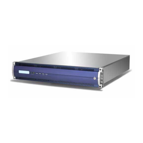
- Page 1 ERQ12+U4R2 Ultra 320 SCSI to Serial ATA II Disk Array System & ERQ12+F2R2 Fibre Channel to Serial ATA II Disk Array System Hardware User Manual...
-
Page 3: Table Of Contents
Components ......................4 Closed Front Panel ................... 4 Open Front Panel ..................... 5 Disk Tray ......................6 ERQ12+U4R2 Rear View ................. 7 ERQ12+F2R2 Rear View ................. 8 Installing Disks ...................... 9 Making Connections ................... 11 Connecting the Host Interface ................ 11 Connecting a network .................. -
Page 5: Preface
Preface About this Manual This manual is designed to make the disk array system as easy to use as possible. Information contained in this document has been checked for accuracy, but no guarantee is given that the con- tents are correct. Information and specifications are subject to change without notice. Copyright Notice ©... - Page 6 Q12+ Serial ATA II Disk Array Systems Important Safety Instructions, Care and Handling Before starting, take a few minutes to read this manual. Read all of these instructions and save this manual for later reference. Protect the disk array system from extremely high or low temperatures.
- Page 7 Q12+ Serial ATA II Disk Array Systems The appliance must be grounded. The disk array system is equipped with a 3-wire grounded type of power cord. This power cord will only fit into a grounded type of power outlet.
- Page 8 Q12+ Serial ATA II Disk Array Systems Placement Notes • The disk array system LCD panel can be damaged by exposure to direct sunlight. Limit exposure to subdued or indirect sunlight only. • The disk array system should be used only in clean environments that are free from airborne contaminants such as dust, dirt, and smoke.
-
Page 9: Chapter 1 System Requirements
1 System Requirements Ensure that the following requirements are met before installing the disk array system. Operating Environment • 15 cm (6-inches) of space around the disk array system for proper ventilation • ambient temperature of 5°C to 40°C (40°F to 104°F) •... -
Page 10: Host Interface
Ultra Fibre Channel Interface The easyRAID Q12+F2R2 has dual 2 Gbit fibre channel interfaces with SFP connectors for link- age to a fibre channel switch or host computer interface card. With the correct SFP transceiver and optical cable, the following transmission distances can be achieved. -
Page 11: Chapter 2 Basic Configuration
The disk array system is heavy. Be careful when lifting and moving it. Front Panel Keys GUI Installation Disk Array System CD-ROM (option) HPD to VHDC Ultra320 Terminator VHDC VHDC to VHDC Ultra320 SCSI Cable (easyRAID (easyRAID Q12+U4R2 SCSI Cable (easyRAID Q12+U4R2 Only) Only) Q12+U4R2 Only) Screw pack Fix Screw... -
Page 12: Components
Q12+ Serial ATA II Disk Array Systems Components Closed Front Panel Power P/S Fail Access Enter 5 6 7 Name Description Displays warning, operating, and configuration LCD panel information. Power-on indicator Indicates the disk array system power is on. -
Page 13: Open Front Panel
Q12+ Serial ATA II Disk Array Systems Open Front Panel 10 11 Tray LED Indication Color Status Bule Access Green Disk Online No Disk Name Description Disk trays 1-12 Removable hot swap disk trays 1-12 Front panel door Protects the disks and houses the LCD panel... -
Page 14: Disk Tray
Q12+ Serial ATA II Disk Array Systems Disk Tray Front Name Description Power/Error indicator LED Different colors indicate different disk states: • Green – Disk online • Orange – Disk full • Red – No disk This blue LED indicates that the disk is being Access indicator LED accessed. -
Page 15: Erq12+U4R2 Rear View
Q12+ Serial ATA II Disk Array Systems easyRAID Q12+U4R2 Rear View Name Description Cooling fan 1 System cooling fan. Host Port 2 Connects to the host server. (Secondary SCSI channel) Host Port 1 Connects to the host server. (Primary SCSI channel) RS-232 Port Connects to a VT100 terminal or equivalent. -
Page 16: Erq12+F2R2 Rear View
Q12+ Serial ATA II Disk Array Systems easyRAID Q12+F2R2 Rear View Name Description Cooling fan 1 System cooling fan. Host Port 2 Connects to the host server. (Secondary fibre channel) Host Port 1 Connects to the host server. (Primary fibre channel) RS-232 Port Connects to a VT100 terminal or equivalent. -
Page 17: Installing Disks
Q12+ Serial ATA II Disk Array Systems Installing Disks This section describes how to install disks in the disk array system. 1 Unlock the front panel door, then pull it open. Tray LED Indication Color Status Bule Access Green... - Page 18 Q12+ Serial ATA II Disk Array Systems 5 Slide the disk tray back into the empty slot (A), then slowly close the disk tray handle (B). 6 Repeat steps 2 to 5 until all of the required disks have been installed.
-
Page 19: Making Connections
1 (primary SCSI channel) at the rear of the disk array system. CO M CO M UP S UP S 2 Connect the Ultra320 SCSI cable (B) to the left connector of the easyRAID Q12+U4R2 host port 1 (primary SCSI channel) at the rear of the disk array system. - Page 20 Q12+ Serial ATA II Disk Array Systems Fibre Channel Interface The easyRAID Q12+F2R2 has dual 2 Gbit fibre channel interfaces. Each interface can be used with optical or copper transceivers and cables. Follow these instructions to make optical connections.
-
Page 21: Connecting A Network
Q12+ Serial ATA II Disk Array Systems Connecting a network Connect the network cable to the RJ-45 port at the rear of the unit. C O M U PS... -
Page 22: Connecting And Turning On The Power
Q12+ Serial ATA II Disk Array Systems Connecting and Turning on the Power 1 Plug a power cable (A) to a power connector at the rear of the unit, then plug the second power supply cable into the second power connector (B). -
Page 23: Mounting In A Rack
Q12+ Serial ATA II Disk Array Systems Mounting in a Rack When the disk array system is completely set up, it can be installed in a standard 19-inch rack. Follow the instructions in this section to install the disk array system in a rack. -
Page 24: Installing The Rail Extenders
Q12+ Serial ATA II Disk Array Systems Installing the Rail Extenders Follow these instructions to fit the rail extenders if required. 1 If required, bolt the rail extenders into place as shown using the small bolts provided. 2 Slide the disk array system into the rack and bolt it into place with the supplied fixing screws. -
Page 25: Chapter 3 Maintenance Replacing A Disk
3 Maintenance Replacing a Disk A disk failure is indicated when the Power/Error LED at the front of the drive tray turns red and the audible alert sounds. Note Turn off the audible alert by pressing the Up and Down function but- tons on the front panel twice simultaneously. -
Page 26: Replacing A Power Supply
Q12+ Serial ATA II Disk Array Systems Replacing a Power Supply The disk array system is equipped with a Power Supply Fail Indicator LED at the front of the unit that turns red when one of the power supplies fails. The message “Power x failure” also appears on the LCD panel, where x refers to power supply 1, or 2, and an audible alert sounds. - Page 27 Q12+ Serial ATA II Disk Array Systems 4 Pull the power supply handle out. CO M UP S 5 Remove the faulty power supply by pulling the power supply handle A and pressing the release catch B at the same time.
-
Page 28: Upgrading Memory
Q12+ Serial ATA II Disk Array Systems Upgrading Memory The disk array system takes a single DDR-333 184-pin DIMM with a maximum capacity of 2 GB. Follow these instructions to upgrade the memory. 1 Loosen the screws holding the controller cage in place. - Page 29 Q12+ Serial ATA II Disk Array Systems 4 Gently push the new DIMM into the socket, then push the corners of the DIMM down. The DIMM is secured by the DIMM retaining clips. Note The DIMM module will fit in only one direction. Do not force the DIMM into place.
-
Page 31: Appendix
• Audible alarm/disable alarm • LED indicator on disk failures Connectors • 4 x 2-Gbit Fibre ports (2 channels), easyRAID Q12+F2R2 model only • 4 x Ultra320 SCSI ports(2 channels), easyRAID Q12+U4R2 model only • 1 x RS-232 Serial port (115200, 8, N, 1) •... - Page 32 Q12+ Serial ATA II Disk Array Systems Item Specification Controller Intel i80331 64-bit RISC microprocessor Disk Interface SATA II (3.0 Gb/s) Disk Channels 12 channels Disk Interface Chipset Marvell MV88SX8050 Memory Type PC-400 184-pin DIMM Memory Sockets Memory Size...
Need help?
Do you have a question about the ERQ12+U4R2 and is the answer not in the manual?
Questions and answers