
Related Manuals for easyRAID S8-U4TT


Summary of Contents for easyRAID S8-U4TT
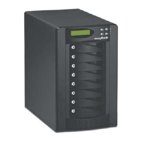
- Page 1 Ent er easyRAID S8-U4TT Ultra 320 SCSI to Serial ATA Disk Array System & easyRAID S8-F2TT Fibre Channel to Serial ATA Disk Array System Hardware User Manual...
- Page 3 Preface About this Manual This manual is designed to make the disk array system as easy to use as possible. Information contained in this document has been checked for accuracy, but no guarantee is given that the con- tents are correct. Information and specifications are subject to change without notice. Copyright Notice ©...
- Page 4 S8 Serial ATA Disk Array Systems Important Safety Instructions, Care and Handling Before starting, take a few minutes to read this manual. Read all of these instructions and save this manual for later reference. Protect the disk array system from extremely high or low temperatures.
- Page 5 S8 Serial ATA Disk Array Systems The appliance must be grounded. The disk array system is equipped with a 3-wire grounded type of power cord. This power cord will only fit into a grounded type of power outlet. If an extension cord or a power center is used with the...
- Page 6 S8 Serial ATA Disk Array Systems Placement Notes • The disk array system LCD panel can be damaged by exposure to direct sunlight. Limit exposure to subdued or indirect sunlight only. • The disk array system should be used only in clean environments that are free from airborne contaminants such as dust, dirt, and smoke.
-
Page 7: Table Of Contents
Table of Contents Preface........................i Chapter 1 Overview Features ........................ 1 Understanding RAID ..................... 2 Just a Bunch Of Disks ..................2 RAID Levels ..................... 2 Hot Spare Disks ....................5 RAID Combinations ..................5 Summary of RAID Levels ................. 6 System Requirements ................... -
Page 9: Chapter 1 Overview
• Fast 64-bit RISC CPU based RAID controller with up to 1 GB of cache in an SO-DIMM • Ultra SCSI (easyRAID S8-U4TT) or fibre channel (easyRAID S8-F2TT) host interfaces • Audible alarm, disk tray LED, and LCD panel failure indicators •... -
Page 10: Understanding Raid
S8 Serial ATA Disk Array Systems Understanding RAID Read this section to understand how to balance data availability, access rate, and capacity man- agement needs. Just a Bunch Of Disks Just a Bunch Of Disks (JBOD) consists of two or more disks that can be different sizes. Disk 1 is completely filled, then disk 2, disk 3, and so on until the final disk is full. - Page 11 S8 Serial ATA Disk Array Systems A RAID 0 array is useful in the following situations: • Storing program image libraries or run-time libraries for rapid loading. A backup exists because these libraries are usually supplied on read-only media.
- Page 12 S8 Serial ATA Disk Array Systems RAID 3 In RAID 3, data is divided into pieces; the parity of these pieces is calculated; and the pieces are written to separate disks in parallel with the writing of the parity to a dedicated disk. This process is called striping with parity.
-
Page 13: Hot Spare Disks
S8 Serial ATA Disk Array Systems RAID 5 In RAID 5, data is divided into pieces; the parity of these pieces is calculated; and the pieces and parity are written to separate disks in parallel. The parity is written to a different disk each time. -
Page 14: Summary Of Raid Levels
S8 Serial ATA Disk Array Systems Summary of RAID Levels The following table summarizes the performance characteristics of each RAID level. A high availability or access rate number indicates high availability or quick access rate. Array Access Capacity Availability... -
Page 15: System Requirements
S8 Serial ATA Disk Array Systems System Requirements Ensure that the following requirements are met before installing the disk array system. Operating Environment • 15 cm (6 inches) of space around the disk array system for proper ventilation • ambient temperature of 5°C to 40°C (40°F to 104°F) •... -
Page 16: Host Interface
Ultra Fibre Channel Interface The easyRAID S8-F2TT has dual 2 Gbit fibre channel interfaces with SFP connectors for linkage to a fibre channel switch or host computer interface card. With the correct SFP transceiver and optical cable, the following transmission distances can be achieved. -
Page 17: Chapter 2 Basic Configuration
Contact your supplier if any of the following items are missing or damaged. Caution The disk array system is heavy. Be careful when lifting and moving it. Enter Active Terminator (easyRAID S8-U4TT Only) Disk Array System Front Panel Keys Ultra320 SCSI Cable (easyRAID S8-U4TT Only) -
Page 18: Components
S8 Serial ATA Disk Array Systems Components Front View Name Description Disk trays 1 to 8 Removable hot swap disk trays. Displays warning, operating, and configuration Control panel information. -
Page 19: Control Panel
S8 Serial ATA Disk Array Systems Control Panel Name Description Displays warning, operating, and configuration LCD panel information. Up button Moves up in the LCD menus. Returns to the previous LCD menu without making Escape button changes. Power-on indicator Indicates the disk array system power is on. -
Page 20: Disk Tray
S8 Serial ATA Disk Array Systems Disk Tray Left Right Front Name Description Allows the disk be mounted on the disk tray with the Disk mounting holes screws included with the disk. Prevents unauthorized removal of a disk tray. Opened Tray lock with the included disk tray lock key. -
Page 21: Rear View
S8 Serial ATA Disk Array Systems Rear View Host Port 1 Host Port 2 Name Description RS-232 Port Connects to a VT100 terminal or equivalent. Ethernet Port Used for browser-based configuration. easyRAID S8-U4TT Host Port 1 Connects to the host server. -
Page 22: Installing Disks
S8 Serial ATA Disk Array Systems Installing Disks This section describes how to install disks in the disk array system. Read “Understanding RAID” on page 3 to decide how many disks are required. 1 Unlock the disk tray (A) then pull the disk tray handle to the opened position (B) and remove the disk tray (C). - Page 23 S8 Serial ATA Disk Array Systems 4 Attach the disk to the disk tray with the screws supplied by the disk supplier. 5 Slide the disk tray back into the empty slot (A), push the disk tray handle closed (B), then lock the disk tray (C).
-
Page 24: Making Connections
2 (primary SCSI channel) at the rear of the disk array system. 2 Connect the Ultra320 SCSI cable to the top connector of the easyRAID S8-U4TT host port 2 (primary SCSI channel) at the rear of the disk array system. -
Page 25: Connecting The Rs-232 Cable
Follow these instructions to make optical connections. 1 Insert the LC Optical SFP transceiver (A) in to the easyRAID S8-F2TT host port 1 (pri- mary fibre channel) at the rear of the disk array system. -
Page 26: Connecting And Turning On The Power
S8 Serial ATA Disk Array Systems Connecting and Turning on the Power 1 Connect a power cable to a power supply connector at the rear of the unit. 2 Connect the second power cable to the remaining power supply connector. -
Page 27: Chapter 3 Maintenance Replacing A Disk
3 Maintenance Replacing a Disk A disk failure is indicated when the Power/Error LED at the front of the drive tray turns red and the audible alert sounds. Note Turn off the audible alert by pressing the Up and Down function but- tons on the front panel twice simultaneously. -
Page 28: Replacing A Power Supply
S8 Serial ATA Disk Array Systems Replacing a Power Supply The disk array system is equipped with a Power Supply Fail Indicator LED at the front of the unit that turns red when one of the power supplies fails. The message “Power x failure” also appears on the LCD panel, where x refers to power supply 1, or 2, and an audible alert sounds. - Page 29 S8 Serial ATA Disk Array Systems 2 Unplug the power cable connected to the failed power supply unit. 3 Push the power supply release switch (A) in the direction illustrated and pull the power supply handle out (B) at the same time.
-
Page 30: Upgrading Memory
S8 Serial ATA Disk Array Systems 5 Insert a new power supply unit in the empty power supply unit slot. The power supply automatically locks into position when fully inserted. 6 Reconnect the power cable. Upgrading Memory The disk array system takes a single 200 pin PC200 DDR SDRAM SO-DIMM with a maximum capacity of 1 GB. - Page 31 S8 Serial ATA Disk Array Systems 2 Remove the screws from the daughterboard, then carefully lift the daughterboard (A) from the disk group controller (B). 3 Pull the DIMM retaining clips away from the DIMM, then remove the DIMM. The DIMM springs out of the socket.
- Page 32 S8 Serial ATA Disk Array Systems 5 Replace the screws, then replace the daughterboard on the disk group controller, taking care to align the connectors. 6 Place the top cover on the disk array system, slide it shut, then replace the three screws...
-
Page 33: Replacing A Fan
S8 Serial ATA Disk Array Systems Replacing a Fan A fan failure is indicated by the LCD panel message “Fan x failure”, where x refers to Fan 1 or Fan 2. An audible alert also sounds. Note Turn off the audible alert by pressing the Up and Down function but- tons on the front panel twice simultaneously. - Page 34 S8 Serial ATA Disk Array Systems 2 Loosen the fan enclosure thumbscrews, then pull the fan enclosure out of the chassis. Caution High speed rotating fan blades can cause injury. Wait until both fans have stopped completely before removing either of them.
- Page 35 S8 Serial ATA Disk Array Systems 4 Secure the new fan with the screws removed in the previous step, then insert the power connector. Caution The fan will begin rotating immediately after it is plugged in. Keep your fingers away from the blades.
-
Page 37: Appendix
Appendix Hardware Specifications Item Specification Host Interface SCSI Ultra320 (easyRAID S8-U4TT) or Fibre Channel (easyRAID S8- F2TT) Disk Interface 8 x SATA, 150 MB/s Dimensions 328 mm (H) x 200 mm (W) x 353 mm (D) RAID Functions • Raid levels: JBOD, 0, 1, 0+1, 3, 5, 30 or 50 •... - Page 38 S8 Serial ATA Disk Array Systems Item Specification Controller Intel i80321 64-bit RISC microprocessor Disk Interface Serial ATA I Disk Interface Chipset Marvell MV88SX5080 Memory Type PC200 DDR 200-pin SO-DIMM Memory Sockets Memory Size Up to 1 GB LCD Interface...
Need help?
Do you have a question about the S8-U4TT and is the answer not in the manual?
Questions and answers