Table of Contents
Advertisement
Quick Links
Advertisement
Table of Contents

Related Manuals for Baltimore Aircoil Company TrilliumSeries TRF


Summary of Contents for Baltimore Aircoil Company TrilliumSeries TRF
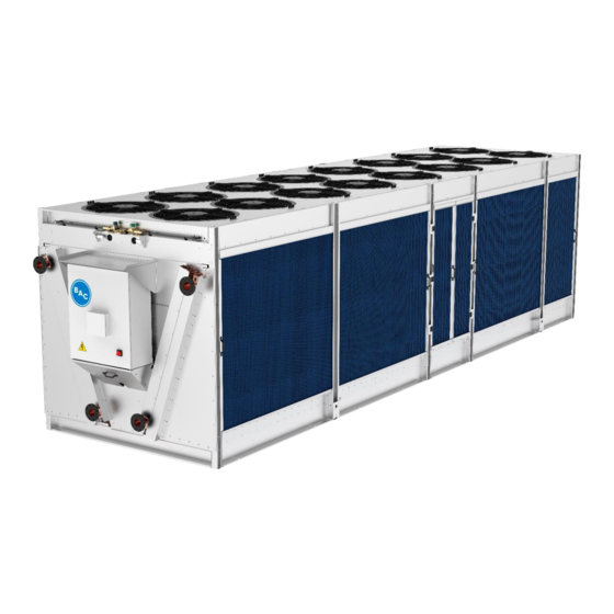
- Page 1 ™ TrilliumSeries Adiabatic Cooler - TRF OPERATION & MAINTENANCE MANUAL...
-
Page 2: Table Of Contents
™ TrilliumSeries Adiabatic Cooler - TRF OPERATION & MAINTENANCE MANUAL Contents 1. Recommended Maintenance Intervals ................................6 2. Parts Map ........................................7 Recommended Spare Parts ..................................8 3. Warnings and Cautions ....................................9 Safety Precautions ..................................... 9 Equipment Precautions .................................... 10 4. - Page 3 Adiabatic Pre-Cooler Water Quality ................................ 15 Biological Control ..................................... 16 6. Cold Weather Operation ..................................... 17 About Cold Weather Operation ................................17 Coil Freeze Protection ....................................17 Minimum Operation ....................................17 Emergency Coil Drain ..................................18 Pre-Cooler Freeze Protection .................................. 18 Protection of Electrical Components ..............................
- Page 4 8. Control Logic ....................................... 40 Sequence of Operation Diagram ................................. 41 9. User Interface ......................................42 Home Menu ....................................... 42 Access Levels ......................................43 Overview Menu ......................................44 Fan Menu ........................................46 All Fans Menu ....................................... 47 Fan X Menu ......................................50 Setpoints ........................................
- Page 5 10. Unit Operation & Storage ..................................92 General ........................................92 Corrosion Protection ....................................92 Inspection ........................................94 Cleaning ........................................94 Start-up ........................................95 Control Panel ......................................95 Control Settings ....................................95 Component Operation ..................................95 Extended Shutdown ....................................97 11. Alarms & Troubleshooting ..................................98 Unit Alarm Codes ....................................
-
Page 6: Recommended Maintenance Intervals
1. Recommended Maintenance Intervals Semi Inspect and clean as necessary Start-Up Monthly Quarterly Annually Annually Inspect general condition of the unit and check unit for unusual noise or vibration ✔️ ✔️ Inspect sump ✔️ ✔️ Inspect water distribution system ✔️ ✔️... -
Page 7: Parts Map
2. Parts Map Coils Integrated Control Panel Fans with Integrated EC Motor Kit Lower Water Collection Channel Adiabatic Pre-Cooler Pads Sump Access Door Water Distribution Inspection Cover Sump Strainer Upper Water Distribution System Drain Valve Access Cover Plenum Access (on opposite face, not shown) Recirculation Pump Pressure Reducing Valve Float Switch... -
Page 8: Recommended Spare Parts
Recommended Spare Parts BAC Factory Authorized Parts are manufactured to meet rigorous specifications and are guaranteed to fit your unit and perform as original equipment. BAC Factory Authorized Parts can be ordered through your local BAC Representative. Most BAC Representatives maintain a local inventory of commonly used parts. For a free unit inspection and a specific parts list for your serial number, contact your local BAC Representative today. -
Page 9: Warnings And Cautions
3. Warnings and Cautions Safety Precautions • : Rotating equipment will cause severe personal injury or death to persons who come in contact. Adequate safeguards (including the use of protective enclosures where necessary) should be taken with this equipment both to safeguard the public from injury and to prevent damage to the equipment, its associated system, and the premises. -
Page 10: Equipment Precautions
Equipment Precautions NOTICE • Drain all water piping feeding the adiabatic pre-cooler to avoid stagnant water conditions. • Water hammer is a common reason for pressure-reducing valve failures. Protective devices should be installed to absorb water hammer for systems with this risk. •... -
Page 11: General Information
4. General Information Adiabatic Cooling Adiabatic cooling uses evaporation to cool air before it passes through a finned heat exchanger. During adiabatic cooling, a wetted pad is used to cool the entering airstream. The pads are specially designed to retain water on the surface to ensure that it does not carry over to the finned coil, minimizing the risk of coil damage. -
Page 12: Methods Of Operation
Methods of Operation Adiabatic Operation As illustrated in Figure 1, when the unit operates in adiabatic mode, either the make-up water connection or the recirculation pumps supply water over the adiabatic pre-cooler pads. Incoming air is humidified as it passes through the adiabatic pre-cooler pads, cooling the air down close to the ambient wet bulb temperature. -
Page 13: Dry Operation
Dry Operation As illustrated in Figure 2, when the unit operates in dry mode, ambient air cools the process fluid in the coils, which then returns to the system. The unit operates in dry mode when the ambient dry bulb temperature is less than the adiabatic switchpoint temperature. -
Page 14: Load Limiting Modes
Load Limiting Modes Night Quiet Night Quiet load limiting mode will reduce sound levels of the unit overnight. When active, the Night Quiet feature limits the maximum fan speed and uses a Night Quiet specific dry switchpoint. This will allow the cooler to run adiabatically at lower outside air temperatures to maintain capacity. -
Page 15: Water Quality
5. Water Quality Process Fluid Water Quality To prevent excessive fouling and internal coil corrosion, the recirculating water quality should remain within the limits indicated in Table 1. A competent water treatment company should be consulted for the specific water treatment to be used that is suitable for all materials of construction used in the entire system. -
Page 16: Biological Control
The adiabatic pre-cooler pads have been treated with an algaecide to minimize the potential for algae growth. In cases where excessive fouling is observed and is suspected to be interfering with the airflow, the adiabatic pre-cooler pads should be cleaned and/or changed more frequently. Biological Control The TrilliumSeries™... -
Page 17: Cold Weather Operation
6. Cold Weather Operation About Cold Weather Operation The equipment can be operated in sub-freezing ambient conditions provided that the proper measures are taken. Listed below are general guidelines that should be followed to minimize the possibility of freeze-up. Customers in climates that reach below freezing temperatures should take necessary precautions to protect the water pipes from freezing. -
Page 18: Emergency Coil Drain
Emergency Coil Drain Do not drain the coils as a regular method of freeze protection. Frequent draining promotes corrosion inside the coil tubes. However, draining is acceptable as an emergency method of freeze protection if the coils are not protected by a glycol solution. If the coils are not protected by a glycol solution, automatic drain valves and vacuum breakers are recommended to drain the coils if flow stops or if the fluid temperature drops below 50°F (10°C) when the ambient temperature is below freezing. -
Page 19: Component Information & Maintenance
7. Component Information & Maintenance : Rotating equipment will cause severe personal injury or death to persons who come in contact. Adequate safeguards (including the use of protective enclosures where necessary) should be taken with this equipment both to safeguard the public from injury and to prevent damage to the equipment, its associated system, and the premises. -
Page 20: Make-Up Water
Make-Up Water General A minimum water flow must be distributed over the adiabatic pre-cooler pads during adiabatic operation. Make-up flow rates are listed in Table 3. Proper flow is preset using a pressure reducing valve and constant flow valve, as shown in Figure 3. Make-up Water Flow Model Number... -
Page 21: Pressure Reducing Valve
Pressure Reducing Valve The adjustable pressure-reducing valve sets the make-up water pressure. The valve must be protected against freezing by heat tracing all exposed make-up water lines if the water cannot be shut off and external piping cannot be drained. The pressure reducing valve is factory set at 45 psi (3 bar) for all TRF model numbers. -
Page 22: Solenoid Valve
NOTICE: Water hammer is a common reason for pressure-reducing valve failures. Protective devices should be installed to absorb water hammer for systems with this risk. Solenoid Valve The solenoid valve is normally closed (fail closed) and slow closing to prevent water hammer. This device is not adjustable and does not have any service or maintenance requirements. -
Page 23: Scaling And Fouling
Scaling and Fouling Airborne debris is caught by the adiabatic pre-cooler pads, which act as air filters and protect the heat exchanger coil from fouling. During adiabatic mode of operation, the pads are rinsed by the recirculating water. The debris that is rinsed from the pads drains with the excess water. -
Page 24: Adiabatic Pre-Cooler Pad Removal
Adiabatic Pre-Cooler Pad Removal NOTICE: To prevent excessive degradation, do not attempt to remove the adiabatic pre- cooler pads wet. Removal of adiabatic pre-cooler pads has been designed as a tool-free operation for quick access for maintenance and to access the interior of the unit for inspection. To remove the adiabatic pre-cooler pads: Remove the adiabatic pre-cooler pad wedge by removing two plastic knobs per wedge assembly. -
Page 25: Water Distribution System
Water Distribution System General The water distribution system is composed of the upper water distribution channels, the lower water collection channels, and the sump. Two sump access doors are provided per unit, one per air inlet face. Refer to Figure 8 for location of the sump access door. -
Page 26: Upper Water Distribution Channel
Upper Water Distribution Channel : Do not walk on the top horizontal surface of the unit. It is not intended to be used as a walking surface or working platform. Risk of falling through the surface, resulting in physical injury or equipment damage. -
Page 27: Lower Water Collection Channel
Lower Water Collection Channel The lower water collection channels collect water coming off the adiabatic pre-cooler pads and redirects it into the sump. At least quarterly and upon seasonal startup, inspect the lower water collection channels for debris. Removal of the adiabatic pre- cooler pads is required to inspect the lower water collection channels, refer to section Adiabatic Pre-Cooler Pad Removal on Page 24. -
Page 28: Recirculation Pump
Recirculation pump Each unit is supplied with two 1/3 HP submersible recirculation pumps as shown in Figure 12. Each pump recirculates water to one air inlet face. Both pumps are located on the same side of the unit and can be accessed via the sump access door. Never lift or carry the pump by the electrical cord, use the pump handle to install/remove pump. -
Page 29: Sump Drain Valve
Sump Drain Valve The sump drain valve is normally open (fail open). The sump drain valve can be accessed from underneath the unit as shown in Figure 14 or via the sump drain valve access cover shown in Figure 11. The sump drain valve access cover is secured with plastic knobs. -
Page 30: Fan And Motor
Fan and Motor General This unit utilizes electronically commutated (EC) axial fan and motor assemblies with integrated speed controller and guard grill. Fans must rotate without obstruction in the direction indicated by arrows on the equipment. If the unit control type is customer input the fans will stop when the input signal is within the signal range listed in Table 4. -
Page 31: Fan And Motor Removal & Installation
Fan and Motor Removal & Installation The following procedure is for field removal and installation of a fan and motor assembly. Turn off power on the unit. Turn power off at the main breaker and follow lock out/tag out procedures. Before disconnecting any power wires, use a multi-meter to verify that there is no voltage. - Page 32 Remove caps from the cable glands. Label and remove wiring from terminal blocks shown in Figure 17. Carefully tag these wires properly to ensure that they are connected at the same location on the new fan. These wires carry polarity sensitive signals. Figure 17.
- Page 33 Lift the fan and motor assembly up and out of the fan deck. If a lifting device is utilized, lift the assembly via the support channels as shown in Figure 19. Be sure to rig the assembly to ensure no damage to the guard grill will occur during lift.
- Page 34 11. Wire terminal blocks shown in Figure 17 following the wire labels created in Step 4. Refer to Table 5 for more information on connection designations. Ensure wires are properly stripped according to Figure 20. Figure 20. Wire Insulation Stripping Diagram Conn.
- Page 35 12. Using zip cable ties secure cables to the fan and motor support channels. Ensure the cable is routed in a U-shape as shown in Figure 21. Figure 21. Fan and Motor Assembly Cable Routing 13. Reinstall cable gland caps with a tightening torque of 4 ± 0.6 Nm. Make sure all cable glands not in use are fitted with dummy plugs.
-
Page 36: Finned Coil Heat Exchanger
Finned Coil Heat Exchanger Finned coil heat exchangers have a maximum allowable working pressure (MAWP) of 200 psi (13.7 bar). Finned coil heat exchanger types will vary depending on the model and design. Proper finned coil heat exchanger maintenance should be followed regardless of coil type. -
Page 37: Programmable Logic Controller (Plc)
Programmable Logic Controller (PLC) General Only the manufacturer may repair the PLC device. If a repair should be necessary, contact your local BAC Representative. Replacing the PLC battery : Battery located in control panel PLC. Risk of explosion resulting in minor or moderate injury or damage to property. - Page 38 It is recommended to replace the battery every 5 years. The motherboard battery is a CR2032 lithium-metal cell. It is used to supply power to the clock integrated on the motherboard. If the battery is depleted or missing, the date and time are displayed incorrectly.
- Page 39 Place a lever made of non-electrically conductive material on the negative pole of the battery holder below the battery. Lift the battery side out of the holder. The battery is now in an inclined position as shown in Figure 24. Figure 24.
-
Page 40: Control Logic
8. Control Logic The controller controls the fan speed based on the actual fluid outlet temperature and the standard or free cooling set point, ensuring a minimum electrical consumption and noise level. The PLC will operate as described in Figure 25. The process fluid temperature set point and the adiabatic switchpoint are adjustable via the Setpoint menu. -
Page 41: Sequence Of Operation Diagram
Sequence of Operation Diagram Figure 25. Sequence of Operation Diagram TrilliumSeries™ Adiabatic Cooler - TRF Operation & Maintenance Manual – Control Logic Page | 41... -
Page 42: User Interface
9. User Interface Home Menu The screen or Human Machine Interface (HMI) home menu is shown in Figure 26. The home menu displays leaving fluid temperature or customer input command, leaving fluid temperature setpoint or customer input command, control mode, fan command, and system messages. -
Page 43: Access Levels
Access Levels Multiple access levels are present within the software. By pressing the “Logout” button in the upper right corner of the screen as shown in Figure 26 a user can enter the login screen as shown in Figure 27. A password is required to access each level other than user. -
Page 44: Overview Menu
Overview Menu The HMI is divided into 4 sections as shown in Figure 28. 1. HMI header (top) 2. Main menu (bottom), 3. Sub menu (left) 4. Information section (right) Menu and sub menu names are shown in Table 9. Figure 28. - Page 45 When selecting a menu option that requires data entry, a screen will appear as shown in Figure 29. Pressing the “OK” button will modify the writable menu option with the value at the top. Pressing the “Cancel” button returns the user to the previous menu.
-
Page 46: Fan Menu
Fan Menu Figure 30 shows the fan menu. The color of the dot in each fan icon reflects that fan’s status: Good (green), Alarm (red), Offline (blue). Fan X’s status will show as “Good” when there are no active fan alarms. Fan X’s status will show as “Alarm” when any fan alarm is active. -
Page 47: All Fans Menu
All Fans Menu Figure 31. All Fans Menu, Overview Parameter Description Max Fan Speed Maximum fan speed for all fans as a % of total fan speed. Fan Command Read only Average Fan Speed Read only Emergency Speed Speed at which all fans will run in case of loss of communication Table 10. - Page 48 Figure 32. All Fans Menu, Analog Data The Analog Data (shown in Figure 32) displays fan data averaged across all available fans. Fan Alarms (shown in Figure 33) displays all possible fan alarms. A green dot indicates the alarm is not active. A red dot indicates the alarm is active. Pressing the “Previous”...
- Page 49 Figure 34. All Fans Menu, Manual The Manual menu shown in Figure 34 is only visible with Technician access level. Refer to Table 8. Access Levels and Passwords on Page 43. Setting the All Fans Manual Mode to Enable transitions the control state to Manual. The Manual menu allows a user to override the fan speed, fan rotation direction, and start, stop, or reset all fans.
-
Page 50: Fan X Menu
Fan X Menu Pressing on Fan X in the Fan Overview menu shown in Figure 30 brings the user to the Fan X Overview tab shown in Figure 35. Analog Data menu reflects Figure 32 and Fan Alarms menu reflects Figure 33 however information displayed on these menus is per fan. - Page 51 The Manual menu shown in Figure 36 is only visible with Technician access level. Refer to Table 8. Access Levels and Passwords on Page 43. Setting the Fan X Manual Mode to Enable will not transition the control state to Manual. The Manual menu allows a user to override the fan speed, fan rotation direction, start, stop or reset a fan as well as read out the fan Modbus address.
-
Page 52: Setpoints
Setpoints Leaving Fluid Control & Customer Input Control Menu With the parameters that can be set in this menu, the user can finetune the behavior of the unit. The Leaving Fluid Control tab shown in Figure 37 is only visible if the Control Type is Leaving Fluid Control. The Customer Input Control tab shown in Figure 38 is only visible if the Control Type is Customer Input. - Page 53 Figure 38. Setpoints Menu, Customer Input Control Parameter Description Operating Mode: Utilizes factory set operating variables that provides a balance of water and energy Default savings. See Table 12. Operating Mode Parameters for more information. Energy Saver mode will enter adiabatic operation more quickly than Default or Operating Mode: Water Saver Operating Modes resulting in lower fan power energy consumption.
-
Page 54: Basin Water Quality Menu
Operating Mode Parameter Default Energy Saver Water Saver Control Range 3.6°F (2.0°C) 0.9°F (0.5°C) 10.0°F (5.5°C) lowers current setpoint Adiabatic Switchpoint by 10.0°F (5.5°C) Stage Timer 120 seconds 60 seconds 300 seconds Table 12. Operating Mode Parameters Basin Water Quality Menu The Basin Water Quality menu shown in Figure 39 and Figure 40 allows a user to adjust parameters shown in Table 13. - Page 55 Figure 40. Setpoints Menu, Basin Water Quality Page 2 of 2 Parameter Description Disable Water Usage Manually disable water usage (prevent adiabatic operation) Time after switch to dry operation before fully draining the water in the basin Basin Retention Time (sump).
-
Page 56: Load Limiting Menu
Load Limiting Menu Refer to section Load Limiting Modes on Page 14 for more information. The Load Limiting menu includes • Night Quiet load limiting mode shown in Figure 41 and Figure 42 with parameters listed in Table 14. • Night Dry load limiting mode shown in Figure 43 and Figure 44 with parameters listed in Table 15. - Page 57 Figure 42. Setpoints Menu, Load Limiting Page 2 of 6 Parameter Description Allows use to either enable or disable the feature. If enabled, the “max fan speed” Night Quiet and “adiabatic switchpoint” parameters will become active during the times set in Enable/Disable the schedule shown in Figure 42.
- Page 58 Figure 43. Setpoints Menu, Load Limiting Page 3 of 6 Figure 44. Setpoints Menu, Load Limiting Page 4 of 6 TrilliumSeries™ Adiabatic Cooler - TRF Operation & Maintenance Manual – User Interface Page | 58...
- Page 59 Parameter Description Night Dry Allows user to either enable or disable the feature. If enabled, no water will be Enable/Disable used during the times set in the schedule shown in Figure 44. If enabled, no water will be used regardless of the schedule shown in Figure 44. In Night Dry Override addition to the on-screen button, the override can also be enabled with the “NightDryOverride”...
- Page 60 Figure 46. Setpoints Menu, Load Limiting Page 6 of 6 Parameter Description Schedule Dry Allows user to either enable or disable the feature. If enabled, no water will be Enable/Disable used during the times set in the schedule shown in Figure 46. If enabled, no water will be used regardless of the schedule shown in Figure 46.
-
Page 61: Maintenance Menu
Maintenance Menu Refer to section Maintenance Modes on Page 14 for more information. The Maintenance menu includes • Coil Clean maintenance mode shown in Figure 47 with parameters listed in Table 17. • Pad Clean maintenance mode shown in Figure 48 with parameters listed in Table 18. •... - Page 62 Figure 48. Setpoints Menu, Maintenance Page 2 of 3 Parameter Description Pad Clean Allows user to either enable or disable the feature. If enabled, the pads will be Enable/Disable rinsed at the time programmed. Pad Clean Duration Time in seconds the pad cleaning cycle lasts. Time Between Pad Number of hours between pad cleaning cycles Cleans...
- Page 63 Figure 49. Setpoints Menu, Maintenance Page 3 of 3 Parameter Description Drain and Dry Allows user to either enable or disable the feature. If enabled, the fans will do a Enable/Disable daily cycle at a 100% fan speed at the time programmed. Drain and Dry Duration Time in seconds the drain and dry cycle lasts.
-
Page 64: Technician Menu
Technician Menu The Technician menu shown in Figure 50 is only visible with Technician access level. Refer to Table 8. Access Levels and Passwords on Page 43. Technician menu parameters are shown in Table 20. Note that changing the PI (proportional and integration) parameters or stage time may result in a hunting phenomenon. -
Page 65: Input & Output
Input & Output With the parameters that can be set in this menu, the user can view the status of all available inputs and outputs. In addition, some output signals can be forced in a certain position to overrule the default programming. Temperatures Menu Temperature menu is shown in Figure 51 and Figure 52 with parameters listed in Table 21. - Page 66 Figure 52. I/O Menu, Temperature Page 2 of 2 Parameter Description Leaving Fluid Temp Process fluid temperature Outside Air Temp Ambient dry bulb temperature Precool X Temp Depressed dry bulb temperature behind the adiabatic pre-cooler section. Table 21. I/O Menu, Temperature Parameters TrilliumSeries™...
-
Page 67: Make Up Menu
Make Up Menu Make Up menu is shown in Figure 53 with parameters listed in Table 22. Figure 53. I/O Menu, Make Up Parameter Description Precooler X Indication if the makeup valves are open or closed. Table 22. I/O Menu, Make Up Parameters TrilliumSeries™... -
Page 68: Pumps Menu
Pumps Menu Pumps menu is shown in Figure 54 with parameters listed in Table 23. Figure 54. I/O Menu, Pumps Parameter Description Indication if the pump is properly running (current detected) or not (no current). The Pump X Current Switch current switch gives an indication of electrical current. -
Page 69: Basin Water Level Menu
Basin Water Level Menu Basin Water Level menu is shown in Figure 55 with parameters listed in Table 24. Figure 55. I/O Menu, Basin Water Level Parameter Description Low/Mid/High Level Indication whether the sensor detects water (up) or not (down) Float Indication if the valve is open (water draining from the sump) or closed (keeping Drain Valve... -
Page 70: Starts And Hours Menu
Starts and Hours Menu The Starts and Hours menu is shown in Figure 56 through Figure 58 with parameters listed in Table 25. Here, the number of starts and operating hours can be reviewed. Pressing the “Reset” button resets the starts and hours for the corresponding device. - Page 71 Figure 58. I/O Menu, Starts and Hours Page 3 of 3 Parameter Description Precooler X Number of starts and operating hours the unit is in adiabatic operation. MUPX Number of starts and operating hours for each make up valve. Drain Valve Number of starts and operating hours for drain valve.
-
Page 72: Manual Menu
Manual Menu The Manual menu will display only with Technician level access. Refer to Table 8. Access Levels and Passwords on Page 43. The Manual menu is shown in Figure 59 and Figure 60 with parameters listed in Table 26. In this menu, the position of a number of digital outputs can be overruled. -
Page 73: Alarms
Parameter Description Makeup Valve X Force either make-up valve on or off. Pump X Contact Force either pump on or off. Drain Valve Force the drain valve open or closed. General Alarm Force the general alarm contact on or off. Table 26. -
Page 74: Alarm Details Page
Alarm Details Page Figure 62 is an example of the Alarm Details page. All possible alarms are listed in Table 37 through Table 62. There are 3 buttons on the left-hand side labeled Trigger Criteria, Release Criteria, and Troubleshooting. Pressing any of these buttons displays the respective information in the table for each alarm. -
Page 75: Settings
Settings With the parameters that can be set in this menu, the user can configure the behavior of the unit. Setup Menu The Setup menu is shown in Figure 63 through Figure 65 with parameters listed in Table 28. Figure 63. Settings Menu, Setup Page 1 of 3 Figure 64. - Page 76 Figure 65. Settings Menu, Setup Page 3 of 3 Parameter Description Language Determines the interface language. Determines the units of measurements for the different variables. This can be set to Units either SI or imperial. Determines in what order the day, month and year are shown. This can be set at Date Format MM/DD/YYYY, DD/MM/YYYY or YYYY/MM/DD.
-
Page 77: Modbus Rtu Setup
Modbus RTU Setup Selecting BMS Protocol Modbus RTU from the Setup menu shown in Figure 64 and pressing the “Configure” button displays the Modbus RTU setup menu shown in Figure 66 and Figure 67 with parameters listed in Table 29. Figure 66. -
Page 78: Bacnet Mstp Setup
Parameter Description Modbus Address Sets the units’ network address Set the appropriate baud rate. Possible values (in kbps) are 9.6, 19.2, 38.4, 57.6 or Baud Rate 115.2 Data Bits The number of data bits is always 8 Stop Bits The number of stop bits always 1 Parity The parity is always odd Table 29. - Page 79 Figure 69. Settings Menu, BACnet MSTP Serial Port Parameter Description Device Instance Sets the correct value. Number MAC Address Sets the correct value. Max Master Sets the correct value. Max Info Frames Sets the correct value. Timeout Sets the correct value. Set the appropriate baud rate.
-
Page 80: Modbus Tcp Setup
Modbus TCP Setup Selecting BMS Protocol Modbus TCP from the setup menu shown in Figure 64 and pressing the “Configure” button displays the Modbus TCP setup menu shown in Figure 70 and Figure 71 with parameters listed in Table 31. Figure 70. -
Page 81: Bacnet Ip Setup
Parameter Description Port Number Sets the correct value. DHCP Enable to get address assigned automatically. IP Address Sets the correct value (in IPv4 format). Subnet Mask Sets the correct value (in IPv4 format). Gateway Sets the correct value (in IPv4 format). Sets the correct value (in IPv4 format). - Page 82 Figure 73. Settings Menu, BACnet IP IP Port Parameter Description Device Instance Sets the correct value. Number Network Number Sets the correct value. Port Number Sets the correct value. DHCP Enable to get address assigned automatically. IP Address Sets the correct value (in IPv4 format). Subnet Mask Sets the correct value (in IPv4 format).
-
Page 83: Software Version Menu
Software Version Menu The Software Version menu is shown in Figure 74 through Figure 76 with parameters listed in Table 33. Figure 74. Settings Menu, Software Version Page 1 of 3 Figure 75. Settings Menu, Software Version Page 2 of 3 TrilliumSeries™... - Page 84 Figure 76. Settings Menu, Software Version Page 3 of 3 Parameter Description Software Version Indicates the current version. Control Version Indicates the current version. TwinCAT Version Indicates the current version. TwinCAT HMI Server Indicates the current version. Version OS Version Indicates the current version.
-
Page 85: Technician Menu
Technician Menu The Technician menu is only displayed and accessible with Technician access level. Refer to Table 8. Access Levels and Passwords on Page 43. The Technician menu is shown in Figure 77 and Figure 78 with parameters listed in Table 34. Figure 77. - Page 86 Figure 78. Settings Menu, Technician Page 2 of 2 Parameter Description Allows user to enable or disable the feature. If enabled, all statuses will be logged at Data Logging regular intervals (see sampling period). Sampling Period Interval at which all statuses are stored to the log (if enabled). Download to USB Export to log file to a USB storage device.
-
Page 87: Data Logging Retrieval
Data Logging Retrieval Onboard data logging records and stores data listed in Table 35 which can be loaded onto a portable USB storage device in a comma separated value (CSV) file. The sampling period is determined by the Sampling Period shown in Figure 77 and listed in Table 34. - Page 88 Variable Name Description CoCdrainActive Cycles of Concentration Drain Active 0 = CoC Drain is inactive 1 = CoC Drain is active NumCoCs Number of Cycles of Concentration till Basin drain CoCcount Cycles of Concentration Count Number of Cycles of concentration that have occurred since the last drain BasinRetentionTime Basin Retention Time [hours] The amount of time in Dry mode that the unit will hold the basin...
- Page 89 Variable Name Description NightQuietAdiaSP Night Quiet Adiabatic Switchpoint [°C] UnitMode Control State (from State Machine) PrecoolerXStatus Precooler X status 0 = Lead 1 = Lag Unit Alarm Code (see Table 63. Unit Alarm Codes) UnitAlarmCode Fan Alarm Code (see Table 64. Fan Alarm Codes ) FanAlarmCode GeneralAlarmDO General Alarm DO...
-
Page 90: Readdress New Fan
Readdress New Fan Replacement fans must be readdressed prior to unit operation. Refer to section Fan and Motor Removal & Installation on Page 31 for instructions on removing and installing fans. Each fan needs to be assigned a unique address, starting with “1,2,3,…”. -
Page 91: Headless Hmi
Figure 80. Settings Menu, Technician Page 2 of 2 Fan Detect Headless HMI The control panel is equipped with a headless HMI feature allowing a user to view the HMI on an external device. Follow the below instructions to utilize the headless HMI feature. Navigate to Settings menu, Setup Page 3 of 3 as shown in Figure 65. -
Page 92: Unit Operation & Storage
10. Unit Operation & Storage TrilliumSeries™ Adiabatic Products are shipped fully wrapped. If the unit is going to remain in outdoor storage in excess of three months prior to installation, remove the stretch wrap and follow the prolonged outdoor storage recommendations listed in the TrilliumSeries™... - Page 93 Long Term Care of Stainless Steel When the percentage of chromium in steel exceeds 10.5%, it is called stainless steel. The chromium in the steel reacts with the oxygen in the air to form a chromium-oxide surface layer, also called the passivation layer that provides the corrosion resistance in stainless steel.
-
Page 94: Inspection
Inspection • Conduct external inspection of the equipment. Check for leaks, corrosion, and any structural damage. • Conduct internal inspection of the equipment. Check for anything unusual such as structural or mechanical component damage. • Inspect the pump(s), make-up valve(s), and drain valve. Remove any construction debris from inside the valves/sump. •... -
Page 95: Start-Up
Start-up Control Panel Verify the correct voltage to the control panel with a meter. Before power has been provided to the unit, turn all breakers to the On position inside the control panel. Close the control panel and ensure locks have been fully engaged by rotating 90 degrees on each bolt. Remove any materials from the sump and ensure the sump access doors are closed and secured. - Page 96 16. Navigate to Fans menu, Manual as shown in Figure 34. Use the radio button to turn Manual Mode to Off. 17. Verify the make-up water connection is on and verify the pressure reducing valve is properly set to 45 psi (3 bar) by viewing the pressure setting indicator visible on both sides of the valve.
-
Page 97: Extended Shutdown
Extended Shutdown Perform the following services whenever the unit is shutdown in excess of three days: NOTICE: Do not use steam, high-pressure water, or high-pressure air to clean any component. • Disconnect, lock-out, and tag-out the unit. • Close the shut-off valve in the make-up water line (supplied by others) and drain the sump and all exposed water piping. Heat trace all exposed make-up water lines if the water cannot be shut off and external piping cannot be drained. -
Page 98: Alarms & Troubleshooting
11. Alarms & Troubleshooting All the possible alarms as well as troubleshooting recommendations are listed in Table 37 through Table 62. Unit alarm codes are listed in Table 63 and fan alarm codes are listed in Table 64. Parameter Condition The unit will issue the alarm when all the following are true: •... - Page 99 Parameter Condition The unit will issue the alarm when all the following are true: • Low Level Float = False for 5 consecutive minutes Trigger Criteria • Drain Valve = Closed The unit will release the alarm when the following is true: Release Criteria •...
- Page 100 Parameter Condition The unit will issue the alarm when all the following are true: • Make Up 1 Alarm is Active Trigger Criteria • Make Up 2 Alarm is Active The unit will release the alarm when any of the following are true: •...
- Page 101 Parameter Condition The unit will issue the alarm when the following is true: Trigger Criteria • All fans time out Modbus communications The unit will release the alarm when the following is true: Release Criteria • Any fan regains Modbus communications •...
- Page 102 Parameter Condition The unit will issue the alarm when all the following are true: • Control Type == LFT Control Trigger Criteria • LFT > 85.0 °C The unit will release the alarm when any of the following are true: •...
- Page 103 Parameter Condition The unit will issue the alarm when all the following are true: • Number of Fans ≥ Fan X Trigger Criteria • Fan X Modbus Address D011 MSB bit 1 = 1 The unit will release the alarm when any of the following are true: •...
- Page 104 Parameter Condition The unit will issue the alarm when all the following are true: • Number of Fans ≥ Fan X Trigger Criteria • Fan X Modbus Address D011 LSB bit 5 = 1 The unit will release the alarm when any of the following are true: •...
-
Page 105: Unit Alarm Codes
Unit Alarm Codes Unit Alarm codes listed in Table 63 are enumerations porting a number code to a specific alarm. These codes are used in the Data logging and BMS communications to effectively communicate active alarms. Alarm Unit Alarm Code No Alarm Pump 1 No Current Pump 1 Lock Out... -
Page 106: Fan Alarm Codes
Fan Alarm Codes Fan Alarm codes listed in Table 64 are enumerations porting a number code to a specific alarm. These codes are used in the Data logging and BMS communications to effectively communicate active alarms. Fan Number Fan Alarm Fan Alarm Code No Fan Alarm 100 111 122 133 144 155 166 177... -
Page 107: Bms Communication
12. BMS Communication BACnet IP & Modbus TCP BACnet IP and Modbus TCP shall be connected via the RJ45 bulkhead at the bottom on the control panel. Points List Modbus Data High BACnet Variable Description Type Limit Limit Addresses Registers Year Current Year in YYYY format 30001... - Page 108 Modbus Data High BACnet Variable Description Type Limit Limit Addresses Registers CIFanCMD Customer Input Fan Command (0.0 42052 -100.0) [% Max Fan Speed] in x10 format Only valid if configured for Customer Input mode, type BMS OpMode Operating Mode 42053 MSV1 0 = Undefined 1 = Default...
- Page 109 Modbus Data High BACnet Variable Description Type Limit Limit Addresses Registers Low Level Float Status 12411 0 = Water Level below Float 1 = Water Level above Float Mid Level Float Status 12412 0 = Water Level below Float 1 = Water Level above Float High Level Float Status 12413 0 = Water Level below Float...
- Page 110 Modbus Data High BACnet Variable Description Type Limit Limit Addresses Registers NightDrySunStart Night Dry Schedule Sunday Start 2359 42055 AV17 time in HHMM format NightDryMonStop Night Dry Schedule Monday Stop 2359 42056 AV18 time in HHMM format NightDryMonStart Night Dry Schedule Monday Start 2359 42057 AV19...
- Page 111 Modbus Data High BACnet Variable Description Type Limit Limit Addresses Registers ScheduleDryThuStop Schedule Dry Schedule Thursday 2359 42078 AV40 Stop time in HHMM format ScheduleDryFriStart Schedule Dry Schedule Friday Start 2359 42079 AV41 time in HHMM format ScheduleDryFriStop Schedule Dry Schedule Friday Stop 2359 42080 AV42...
- Page 112 Modbus Data High BACnet Variable Description Type Limit Limit Addresses Registers PadCleanOverride Pad Cleaning Override 2854 BV16 Use this point to force a pad clean cycle 0 = Disable 1 = Override CoilCleanOverride Coil Cleaning Override 2855 BV17 Use this point to force a coil clean cycle 0 = Disable 1 = Override...
- Page 113 Modbus Data High BACnet Variable Description Type Limit Limit Addresses Registers Fan2ActlSpd Fan 2 Speed Feedback in x10 30040 AV65 format [RPM] Fan2Pwr Fan 2 Power in x10 format [kW] 30041 AV66 Fan2Curr Fan 2 Current in x10 format [A] 30042 AV67 Fan2Hrs...
- Page 114 Modbus Data High BACnet Variable Description Type Limit Limit Addresses Registers Fan6Curr Fan 6 Current in x10 format [A] 30062 AV83 Fan6Hrs Fan 6 run hours [hours] 30063 AV84 Fan7status Fan 7 status 30064 MSO12 0 = Disabled/Offline 1 = Normal 2 = Alarm Fan7ActlSpd Fan 7 Speed Feedback in x10...
- Page 115 Modbus Data High BACnet Variable Description Type Limit Limit Addresses Registers Fan11status Fan 11 status 30084 MSO16 0 = Disabled/Offline 1 = Normal 2 = Alarm Fan11ActlSpd Fan 11 Speed Feedback in x10 30085 AV101 format [RPM] Fan11Pwr Fan 11 Power in x10 format [kW] 30086 AV102 Fan11Curr...
- Page 116 Modbus Data High BACnet Variable Description Type Limit Limit Addresses Registers Fan15ActlSpd Fan 15 Speed Feedback in x10 30105 AV117 format [RPM] Fan15Pwr Fan 15 Power in x10 format [kW] 30106 AV118 Fan15Curr Fan 15 Current in x10 format [A] 30107 AV119 Fan15Hrs...
- Page 117 ™ TrilliumSeries Adiabatic Cooler - TRF OPERATION & MAINTAINANCE MANUAL Baltimoreaircoil.com ©2022 Baltimore Aircoil Company | 7600 Dorsey Run Road | Jessup, MD 20794 | 410.799.6200 | RGOMTRF303_R1.0...
Need help?
Do you have a question about the TrilliumSeries TRF and is the answer not in the manual?
Questions and answers