
Subscribe to Our Youtube Channel
Related Manuals for Baltimore Aircoil Company Trillium Series


Summary of Contents for Baltimore Aircoil Company Trillium Series
- Page 1 MDFCV-EC-ADv06EN DFCV-AD-EC Adiabatic Cooler OPERATING AND MAINTENANCE INSTRUCTIONS...
- Page 2 Recommended maintenance and monitoring programme Baltimore Aircoil Company equipment needs to be properly installed, operated and maintained. Documentation of the equipment used, including a drawing, technical data sheet and this manual should be kept on record. To achieve long, trouble-free and safe operation, it is necessary to establish an operating plan including a programme of regular inspection, monitoring and maintenance.
-
Page 3: Table Of Contents
Table of contents OPERATING AND MAINTENANCE INSTRUCTIONS Construction details General information Operating conditions Connecting pipework Safety precautions Disposal requirements Non-walking surfaces Modifications by others Warranty Water care About water care Biological control Chemical treatment Cold weather operations About cold weather operation Protection against coil freezing Operating instructions TrilliumSeries Coolers with EC fans &... -
Page 4: Construction Details
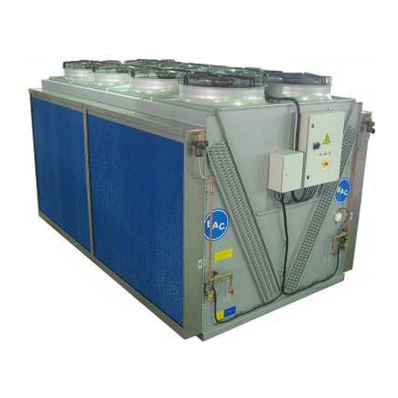
DFCV-AD-EC CONSTRUCTION DETAILS 1. Heat exchanger 2. Coil headers 3. Casing 4. Fans 5. Pre-cooler media 6. Pre-cooler solenoid valve and water filter 7. Pre-cooler drain 8. Pre-cooler flow valve/meter 9. Pre-cooler water distribution header 10. Pre-cooler water distribution pads 11. -
Page 5: General Information
DFCV-AD-EC GENERAL INFORMATION Operating conditions BAC cooling equipment is designed for the operating conditions specified below, which must not be exceeded during operation. • Wind Load: For safe operation of unshielded equipment exposed to wind speeds above 120 km/h installed at a height above 30 m from the ground, contact your local BAC-Balticare representative. -
Page 6: Safety Precautions
Safety precautions All electrical, mechanical and rotating machinery constitutes a potential hazard, particularly for those not familiar with its design, construction and operation. Accordingly, adequate safeguards (including use of protective enclosures where necessary) should be taken with this equipment both to safeguard the public (including minors) from injury and to prevent damage to the equipment, its associated system and the premises. -
Page 7: Non-Walking Surfaces
Non-walking surfaces Access to and maintenance of any component needs to be performed in accordance with all local applicable laws and regulations. If the proper and required access means are not present, temporary structures need to be foreseen. Under no circumstance can one use parts of the unit, that are not designed as an access mean, unless measures can be taken to mitigate any risks that might occur from doing so. -
Page 8: Water Care
DFCV-AD-EC WATER CARE About water care The adiabatic pre-cooler of the unit has been designed as direct-water system, without water re-circulation, without pump. Therefore it is essential that the main cold-water supply connected to the adiabatic pre-cooler has adequate pressure and flow rate for the pre-cooler being installed. The primary water treatment control method for the adiabatic pre-cooler is to provide sufficient water to the pre- cooler medium to keep it flushed. - Page 9 Water quality guidelines for adiabatic Baltiplus 800™ coating pre-cooler frame Temperature < 20 ºC 6.5 – 9 Hardness as (CaCO 50 – 500 mg/l Alkaline as (CaCO < 500 mg/l Total dissolved solids < 1500 mg/l Chlorides < 200 mg/l Sulfates <...
-
Page 10: Biological Control
Data for rapid calculations of Practical Scaling Index for adiabatic pre-cooler Conductivity Temperature Calcium hardness Total alkalinity Alkalinity (µS/cm) ºC (PPM as CaCO (PPM as CaCO (PPM as CaCO pHeq 50-300 10-13 10-15 0.70 10-15 1.10 301-1000 14-17 16-25 0.90 16-25 1.30 1001-3000... -
Page 11: Chemical Treatment
Chemical treatment A biocide program for biological control can be implemented in conjunction with the maintenance program for increased operational safety. However, biological control should not be used in place of good housekeeping. The two most commonly available biocides are chlorine and bromide. These chemicals have widespread success in general application;... -
Page 12: Cold Weather Operations
DFCV-AD-EC COLD WEATHER OPERATIONS About cold weather operation BAC cooling equipment can be operated in sub freezing ambient conditions provided the proper measures are taken. Listed below are general guidelines which should be followed to minimize the possibility of coil freeze-up. As these guidelines may not include all aspects of the anticipated operation scheme, system designer and operator must thoroughly review the system, location of the equipment, controls and accessories to ensure reliable operation at all times. -
Page 13: Operating Instructions
DFCV-AD-EC OPERATING INSTRUCTIONS TrilliumSeries Coolers with EC fans & factory installed control panel Each unit is equipped with a control panel and a power panel. The fan speed is controlled and the adiabatic pre-cooling is activated by a PLC integrated into the electrical panel. Control logic The fan speed is controlled on the basis of the actual process fluid temperature at the exit of the unit and the design leaving temperature, ensuring a minimum in electrical consumption and noise levels. -
Page 14: Operating Instructions Digital Controller
CONTROL PANEL The control panel contains the digital controller. At the inside of the control panel, the following component can be found: • Pad Maintenance Switch (DVW) AUTO(II): Pads will be (de)activated based on the units programming HAND(I): Pads will be forced in wet mode resulting in adiabatic operation Pad Maintenance Switch (DVW) for EC fans POWER PANEL At the outside of the power panel, the following components can be found:... -
Page 15: Monitoring Of Process Information
DEFAULT MENU The overview of different operational parameters and their settings (ex: temperatures, set point, theoretical frequency, actual frequency, and some general statuses) ALARMS This menu can be accessed by pressing on the Alarm button (Triangle with exclamation mark). To acknowledge an alarm, press the Alarm button (Triangle with exclamation mark). If the source of the alarm has disappeared, so will the alarm message, otherwise the alarm will stay present. - Page 16 DIGITAL BUS SYSTEM A bus connection from the digital controller for monitoring can be wired to the terminal strip. Depending on the required communication protocol, a different optional communications card can be installed in the controller. W W W . B A L T I M O R E A I R C O I L . E U...
-
Page 17: Maintenance Procedure
DFCV-AD-EC MAINTENANCE PROCEDURE Checks and adjustments ADIABATIC PRE-COOLER WATER FLOW A minimum water flow must be distributed over the adiabatic pre-cooler as per minimum water flow rates. (See table below "Minimum recommended adiabatic pre-cooler water flow rates"). The water flow will depend on the supply water pressure, and can be set by adjusting the adjustment screw on the water flow valve on the flow meter (See figure below). - Page 18 Model Number of fans Minimum pre-cooler water flow per unit DFCV-EC9122-* 4 fans 14 l/min DFCV-EC9123-* 6 fans 22 l/min DFCV-EC9124-* 8 fans 28 l/min DFCV-EC9125-* 10 fans 36 l/min DFCV-EC9126-* 12 fans 44 l/min DFCV-EC9127-* 14 fans 50 l/min Recommended adiabatic pre-cooler water flow rates ADIABATIC PRE-COOLER SET-POINT The operation of the adiabatic pre-cooling sections is controlled by the digital controller.
-
Page 19: Inspections And Corrective Actions
Inspections and corrective actions GENERAL CONDITION OF THE EQUIPMENT Once a year the general condition of the equipment should be inspected. The inspection should focus on: • Signs of corrosion • Accumulation of dirt and debris If there are any signs of blemishes or corrosion, the affected area should be thoroughly wire brushed and re-coated. The recommended procedure is to use a base coat of ZRC (Zinc Rich Compound). -
Page 20: Fan Replacement
HEAT EXCHANGER COIL The finned heat exchanger coil is susceptible to corrosion and entrapment of airborne particulates (coil fouling). The speed of coil fouling can be reduced, and the service lifetime of the finned coil can be extended, if the pre- cooling media is kept in place also during cold seasons, to act as air filter. - Page 21 A. Control Panel B. 4 Fan Unit C. 6 Fan Unit D. 8 Fan Unit E. 10 Fan Unit F. 12 Fan Unit G. 14 Fan Unit Diagram showing sequence of fan motor address Schematic of internal motor terminal strip Conn.
-
Page 22: Cleaning Procedures
Cleaning procedures CAUTION Stainless steel parts can be sharp. Avoid risk for cutting injury by wearing the proper protective equipment ! WATER DISTRIBUTION PIPE AND STRAINERS The water distribution piping of the adiabatic pre-cooling section is supplied with in line water filters, filtering water particles from the incoming water. - Page 23 Flexible sleeve connection 3. Gently pull out the water feed assembly. Waterfeed connection 4. Pull the copper tube pipe downwards to release it from the plastic holders. Release copper collector from plastic holders 5. Carefully remove the collector from the pre-cooler. 6 Maintenance procedure 6 Maintenance procedure W W W .
- Page 24 Remove copper waterfeed pipe 6. Use a 3,5 mm drill to clean by hand the spraying holes from any dirt accumulation. Clean spraying holes 7. On the collector there is an alignment hole. Mark its position on the opposite side of the collector to assist you in placing the collector back in the pre-cooler section.
- Page 25 Plastic clip with longer screw 9. First put the collector through the hole of the side gable. Note that this is the opposite side of the alignment hole. Installation of copper waterfeed pipe 10. Use the mark you made on the collector to locate the correct position of the alignment hole. Push the collector upward to clamp it securely into the plastic holders.
- Page 26 Waterfeed assembly 12. Tighten the sleeve clamps to secure the water feed assembly in place. Flexible sleeve connection with sleeve clamps 13. Connect the flexible pipe to the city water supply. Use the "pad maintenance" switch to open the city water valve.
-
Page 27: Adiabatic Pre-Cooling Media
Adiabatic pre-cooling media CLEANING The digital controller provides automatic periodic cleaning of the pre-cooling media. In extraordinary circumstances, if manual rinsing is required, the recommended procedure for cleaning of the pre- cooling media is to turn the "pad maintenance switch", provided on the door of the electrical panel, to the "Hand" position for a period of 1 to 2 hours. - Page 28 Removal water distribution pads Removal pre-cooling media CAUTION The pre-cooling media have a front side and a back side and need to be (re)installed in the correct position to ensure full wetting over the depth of the media and to ensure maximum efficiency. The blue coloured side needs to be at the outside.
- Page 29 Model Number of Number of adiabatic pre-cooling Number of bottom fans sections/cooler drains/cooler DFCV-EC9126-* DFCV-EC9127-* Number of adiabatic pre-cooler sections and drains Each pre-cooler section has a sloping pan, assuring complete water drainage and discharge of any floating solids to the sewer. Larger debris will however accumulate and settle in the gutter system and may be too large to drain via the bottom drain and finally may block the bottom drain.
-
Page 30: Comprehensive Maintenance
DFCV-AD-EC COMPREHENSIVE MAINTENANCE About comprehensive maintenance In order to ensure maximum efficiency and minimum downtime of your evaporative cooling system, it is recommended to establish and execute a programme of preventive maintenance. Your local BAC Balticare representative will assist you in establishing and implementing such programme. The preventive maintenance programme must not only avoid that excessive downtime occurs under unforeseen and unwanted conditions, it also ensures that factory authorized replacement parts are used, which are designed to fit and for their purpose carry the full factory warranty. -
Page 31: Further Assistance & Information
DFCV-AD-EC FURTHER ASSISTANCE & INFORMATION Balticare BAC has established a specialized independent total care company called Balticare. The BAC Balticare offering involves all elements required to ensure a safe and efficient operation of your evaporative cooling products. From a full range of risk assessment to selective water treatment, training, testing, record keeping and annual system overview. - Page 32 COOLING TOWERS CLOSED CIRCUIT COOLING TOWERS ICE THERMAL STORAGE EVAPORATIVE CONDENSERS HYBRID PRODUCTS PARTS & SERVICES www.BaltimoreAircoil.eu info@BaltimoreAircoil.eu Please refer to our website for local contact details. Industriepark - Zone A, B-2220 Heist-op-den-Berg, Belgium © Baltimore Aircoil International nv...
Need help?
Do you have a question about the Trillium Series and is the answer not in the manual?
Questions and answers