Table of Contents
Advertisement
Quick Links
Advertisement
Table of Contents
Troubleshooting

Related Manuals for Synrad Novanta 48 Series


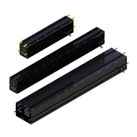
Summary of Contents for Synrad Novanta 48 Series
- Page 1 48 Series User Manual ENGINEERED BY SYNRAD...
-
Page 2: Table Of Contents
IMPORTANT INFORMATION PAGE Table of Contents Important Information ..................................6 Trademark & Copywrite ..................................8 Warranty Information ..................................8 Sales, Application & Support ................................9 Sales & Application .................................... 9 Customer Service ....................................9 Technical Support ....................................9 Reference Materials ..................................10 EU Headquarters ..................................... - Page 3 IMPORTANT INFORMATION PAGE 48-5 rear panel ....................................35 Technical reference ..................................36 Technical overview ..................................36 Introduction ..................................... 37 Plasma section ....................................37 Optical resonator ..................................... 37 Controlling Laser Power ................................... 38 Fault shutdown conditions ................................38 Cooling ......................................39 Setting coolant temperature ................................
- Page 4 IMPORTANT INFORMATION PAGE Maintenance and Troubleshooting ..............................75 Maintenance ....................................75 Disabling the Series 48 laser ................................76 Daily inspections ....................................76 Storage/shipping ..................................... 76 Coolants ......................................77 Cleaning guidelines ..................................78 Cleaning optics ....................................78 Troubleshooting ....................................80 Resetting faults ....................................80 Operational flowchart ..................................
- Page 5 IMPORTANT INFORMATION PAGE Figure 4-2 “Flying optics” beam path .............................. 43 Table 4-2 Assist gas purity specifications ............................44 Table 4-3 Input signal specifications..............................44 Table 4-4 Tickle pulse specifications..............................45 Figure 4-3 Tickle pulse waveform..............................45 Figure 4-4 Series 48-2 kHz waveform.
-
Page 6: Important Information
IMPORTANT INFORMATION PAGE Important Information For your protection, carefully read these instructions before installing and operating the scan head. Retain these instructions for future reference. Novanta reserves the right to update this user manual at any time without prior notification. If product ownership changes, this manual should accompany the product. - Page 7 IMPORTANT INFORMATION PAGE Customer Support Before contacting Novanta for assistance, review appropriate sections in the manual that may answer your questions. After consulting this manual, please contact one of our worldwide offices between 9 AM and 5 PM local time. Americas, Asia Pacific Novanta Headquarters, Bedford, USA Phone: +1-781-266-5700...
-
Page 8: Trademark & Copywrite
TRADEMARK & COPYWRITE PAGE Trademark & Copywrite NOVANTA© and 48 Series lasers are registered trademarks of NOVANTA. All other trademarks or registered trademarks are the property of their respective owners. 2019 by NOVANTA. All rights reserved. Warranty Information This is to certify that 48 Series lasers are guaranteed by NOVANTA to be free of all defects in materials and workmanship for a period of one year from the date of purchase. -
Page 9: Sales, Application & Support
SALES, APPLICATION & SUPPORT PAGE Sales, Application & Support Novanta Sales and Support NOVANTA® worldwide headquarters are located north of Seattle in Mukilteo, Washington. U.S.A. Our mailing address is: NOVANTA 4600 Campus Place Mukilteo, WA 98275 U.S.A. Phone us at: 1.800.NOVANTA1 (1.800.796.7231) Outside the U.S.: +1.425.349.3500... -
Page 10: Reference Materials
REFERENCE MATERIALS PAGE Reference Materials Your Regional Sales Manager can provide reference materials including Outline & Mounting drawings, Operator’s Manuals, Technical Bulletins, and Application Newsletters. Most of these materials are also available directly from the NOVANTA web site at http://www.Novanta.com. EU Headquarters For assistance in Europe, contact NOVANTA®... -
Page 11: Introduction
INTRODUCTION PAGE Introduction This section contains the following information: • Series 48 Trademark, Copyright & Warranty information • Series 48 guidelines and contents description • Series 48 Nomenclature Warning: Serious Personal Injury Remote interlock faults are not latched on OEM lasers. Clearing the fault condition re-enables the RDY indicator and the laser will bee enabled five seconds after the SHT indicator is lit and a PWM Command signal is applied. -
Page 12: Series 48 Trademark, Warranty & Copyright Information
SERIES 48 TRADEMARK, WARRANTY & COPYRIGHT INFORMATION PAGE Failure to properly package the laser using NOVANTA shipping box and foam/cardboard inserts as shown in Packaging Instructions may void the warranty. Customers may incur additional repair charges due to shipping damage caused by improper packaging. Before beginning any maintenance or inspections of your Series 48 laser, be sure to completely disable the laser by disconnecting the DC Power cable (or cables) from the rear of the laser. -
Page 13: Guidelines & Content
GUIDELINES & CONTENT PAGE Guidelines & Content See the drawings within this Operation Manual when installing and operating your Series 48 laser. Unpacking/Packing, Storage/Shipping, Mounting, Connecting, Cooling Series 48 nomenclature/features Unpacking/packing, storage/shipping, mounting, connecting, cooling NOVANTA® recommends saving all of the laser’s original packaging. It’s unique design assists in preventing damage to your laser during storage, relocation and/or shipping. -
Page 14: Figure 1-1 Series 48 Ship Kit Contents
UNPACKING/PACKING, STORAGE/SHIPPING, MOUNTING, CONNECTING, COOLING PAGE Figure 1-1 Series 48 ship kit contents. Table 1-1 Series 48 ship kit contents. Shipping Box Contents Series 48 Laser Customer communication flier Spare Fuse (as required) Mounting Bolts (not standard) Cooling kit (as required) Maximum torque (48-1) 0.41 Nm or 4 in-lb 6-32 screw, (48-2) 0.41 Nm or 4 in-lb 6-32 screw, (48-5) 1.4 Nm or 12.1 in-lb 10-32 screw. -
Page 15: Series 48 Nomenclature
SERIES 48 NOMENCLATURE PAGE Series 48 nomenclature The Series 48 nomenclature section includes: • Model numbers • Series 48 laser versions The last three characters in the Series 48 model number serve to designate the functional category, cooling method, and model version. The functional category is indicated by either a “K” for Keyswitch or “S” Standard (OEM) for OEM models. -
Page 16: Laser Safety
LASER SAFETY PAGE Laser Safety Read the entire safety section. This will ensure you are familiar with the hazards and warnings prior to starting. Hazard Information – includes equipment label terms and hazards, please familiarize yourself with all definitions and their significance. General &... - Page 17 HAZARD INFORMATION PAGE • Important note: Content specific information and/or recommendations. Read the entire safety section. This will ensure you are familiar with the hazards and warnings prior to starting. Warning: Serious Personal Injury For laser systems being used or sold within the U.S.A., customers should refer to and follow the laser safety precautions described American National Standards Institute (ANSI) document Z136.1-2014, Safe Use of Lasers.
-
Page 18: Disposal
DISPOSAL PAGE Following are descriptions of general hazards and unsafe practices that could result in death, severe injury, or product damage. Specific warnings and cautions not appearing in this section are found throughout the manual. Warning: Serious Personal Injury Do not allow laser radiation to enter the eye by viewing direct or reflected laser energy. CO2 laser radiation can be reflected from metallic objects even though the surface is darkened. - Page 19 THORIUM SAFETY PAGE (A) risk of injury when lifting or moving the unit; (B) risk of exposure to hazardous laser energy through unauthorized removal of access panels, doors, or protective barriers; (C) risk of exposure to hazardous laser energy and injury due to failure of personnel to use proper eye protection and/or failure to adhere to applicable laser safety procedures;...
-
Page 20: Additional Laser Safety Information
ADDITIONAL LASER SAFETY INFORMATION PAGE Additional laser safety information The NOVANTA web site https://www.Novanta.com/resources/general_information/lasersafetyresources contain an online laser safety handbook that provides information on (1) Laser Safety Standards for OEM’s/System Integrators, (2) Laser Safety Standards for End Users, (3) References and Sources, and (4) Assistance with Requirements. -
Page 21: Series 48-1 Label Locations
SERIES 48-1 LABEL LOCATIONS PAGE Series 48-1 label locations Figure 2-1 Hazard label locations (48-1 example). -
Page 22: Series 48-2 Label Locations
SERIES 48-2 LABEL LOCATIONS PAGE Series 48-2 label locations Figure 2-2 Hazard label locations. -
Page 23: Series 48-5 Label Locations
SERIES 48-5 LABEL LOCATIONS PAGE Series 48-5 label locations Figure 2-3 Hazard label locations. -
Page 24: Agency Compliance
AGENCY COMPLIANCE PAGE Agency compliance • Center for Devices and Radiological Health (CDRH) requirements. • Federal Communications Commission (FCC) requirements. • European Union (EU) requirements. NOVANTA lasers are designed, tested, and certified to comply with certain United States (U.S.) and European Union (EU) regulations. - Page 25 (ISM) equipment are fully described in 47 CFR, §18, §§C. NOVANTA 48 Series lasers have been tested and found to comply by demonstrating performance characteristics that have met or exceeded the requirements of 47 CFR, §18, §§C for Radiated and Conducted Emissions.
-
Page 26: European Union (Eu) Requirements Rohs Compliance
PAGE European Union (EU) requirements RoHS compliance NOVANTA 48 Series lasers meet the requirements of the European Parliament and Council Directive 2015/863/EU on the Restriction of the Use of Certain Hazardous Substances in Electrical and Electronic Equipment that establishes maximum concentration values for certain hazardous substances in electrical and electronic equipment. - Page 27 EUROPEAN UNION (EU) REQUIREMENTS ROHS COMPLIANCE PAGE Table 2-4 Class 4 safety features. Required by: Available on: Feature Location Description CDRH EN60825-1 OEM Series 48 On/Off/Reset Key switch controls power to laser electronics. Key Keyswitch Rear Panel Control cannot be removed from switch in the “On”...
- Page 28 EUROPEAN UNION (EU) REQUIREMENTS ROHS COMPLIANCE PAGE Temperature shutdown occurs if temperature of Over Temperature Circuit Element the laser tube rises Protection above safe operating limits Illuminates green when laser temperature is Rear panel indicator within operating limits, Temp Indicator (Green/Red).
-
Page 29: Figure 2-2 Declaration Document
EUROPEAN UNION (EU) REQUIREMENTS ROHS COMPLIANCE PAGE Figure 2-2 Declaration Document. -
Page 30: Operation
OPERATION PAGE Operation Use information in this section to familiarize yourself with Series 48 controls and indicators. Reference the Quick Start Guide for the initial startup process. This section contains the following information: • Controls and indicators – displays and describes exterior controls and indicators on Series 48 Keyswitch and OEM lasers. -
Page 31: Controls And Indicators
CONTROLS AND INDICATORS PAGE Controls and Indicators Figure 3-1 48-1/48-2 Front panel controls and indicators. 48-1/48-2 front panel Aperture Seal – prevents dust from damaging the output coupler during shipping. Remove the red self- adhesive label before applying power to the laser. Shutter Switch (Keyswitch models only) –... -
Page 32: 48-1/48-2 Rear Panel
48-1/48-2 REAR PANEL PAGE Figure 3-2 48-1/48-2 Rear panel controls and indicators. 48-1/48-2 rear panel Power LED – illuminates green when the Keyswitch is turned to the ON position (or when an OEM laser is powered up) to indicate that power is applied to internal circuitry. Lase LED –... -
Page 33: Side Panel
SIDE PANEL PAGE Figure 3-3 Side panel controls and indicators. Side panel DC Power Cables – red (+) and black (–) DC Power input cables are manufactured from #12 AWG (48-1/48- 2) or #8 AWG (48-5) wire and measure 1.1 meters (3.5 feet) in length. Auxiliary Power Connector –... -
Page 34: 48-5 Front Panel
48-5 FRONT PANEL PAGE Figure 3-4 48-5 Front panel controls and indicators. 48-5 front panel Aperture Seal – prevents dust from damaging the output coupler during shipping. Shutter Switch (Keyswitch models only) – manually closes the aperture and interrupts power to the RF section(s). Diode Pointer Power Connector (optional) –... -
Page 35: 48-5 Rear Panel
48-5 REAR PANEL PAGE Figure 3-5 48-5 Back panel controls and indicators. 48-5 rear panel Power LED – illuminates green when the Keyswitch is turned to the ON position (or when an OEM laser is powered up) to indicate that power is applied to internal circuitry. Lase LED –... -
Page 36: Technical Reference
TECHNICAL REFERENCE PAGE Auxiliary Power Connector – provides an optional 30 VDC @ 350 mA source for powering the UC-2000 Controller. An auto-resetting solid-state fuse limits line current. Connector power is active after 30 VDC is applied to the laser. Technical reference Use information in this section as a technical reference for you Series 48 lasers. -
Page 37: Introduction
INTRODUCTION PAGE Introduction Series 48 lasers incorporate the latest technology in sealed carbon dioxide devices, combining the best features of both waveguide and free space CO laser technology. The all-metal laser tube construction features the ruggedness, stable optical support, and small size of waveguide lasers. Its larger bore (4.8 mm) eliminates the high optical power density of waveguide lasers with their predisposition to optical degradation and incorporates the mode purity and easy optical alignment of free space TEM00 lasers. -
Page 38: Controlling Laser Power
CONTROLLING LASER POWER PAGE Controlling Laser Power Electrical description Control of laser operation and power output levels is essentially performed using a single PCB. The Control PCB connects the modulated signal to the RF amplifier. It also provides electronics to monitor performance of RF control, output circuitry, input power, temperature, PWM accuracy, provides outputs to an externally accessible connector, and incorporates reverse polarity protection. -
Page 39: Cooling
COOLING PAGE (closed circuit). Power-On Reset is defeated on all OEM versions. OEM customers must provide this required safety feature elsewhere as part of their equipment integration. Cooling Series 48 electronics are mounted opposite the laser tube in the smaller section of the “H” bay and share the same cooling removal as the plasma tube. - Page 40 SETTING COOLANT TEMPERATURE PAGE Table 4-1 Dew Point Table °F temperatures.
- Page 41 SETTING COOLANT TEMPERATURE PAGE Table 4-1 Dew point temperatures °C (Continued). • Air-condition the room or the enclosure containing the laser. • Install a dehumidifier to reduce the humidity of the enclosure containing the laser. The table above provides dew point temperatures for a range of air temperature and relative humidity values.
-
Page 42: Duo-Lase® Operation (48-5)
DUO-LASE® OPERATION (48-5) PAGE Duo-Lase® operation (48-5) The 48-5 laser combines two laser tubes for twice the output of a standard laser. The outputs from two 25 W sealed CO2 tubes are combined optically to provide a single diffraction-limited beam at 50 W. This optical combining technique is based on the fact that each laser is linearly polarized, allowing the use of a polarization sensitive beam combiner to achieve 98% efficiency in combining the two beams. -
Page 43: Figure 4-2 "Flying Optics" Beam Path
OPTICAL SETUP PAGE Figure 4-2 “Flying optics” beam path Focusing optics When selecting a focusing optic, the primary consideration should be material thickness and any vertical tolerances that occur during final part positioning rather than making a selection based only on minimum spot size. -
Page 44: Control Signals
CONTROL SIGNALS PAGE Table 4-2 Assist gas purity specifications Control signals • Control signals • Operating modes Much of the information provided in this section describes the use of a NOVANTA UC-2000 Universal Laser Controller to provide tickle and PWM Command signals to the laser. If you are using an alternate method of laser control, thoroughly review this section for an understanding of the signal requirements necessary to control NOVANTA®... -
Page 45: Figure 4-3 Tickle Pulse Waveform
CONTROL SIGNALS PAGE Tickle pulse Series 48 lasers require a 1 μs tickle pulse delivered at a nominal 5 kHz clock frequency from the Controller. Tickle pulses pre-ionize the laser gas to just below the lasing threshold so that any further increase in pulse width adds enough energy to the plasma to cause laser emission. -
Page 46: Figure 4-4 Series 48-2 Khz Waveform. The Upper Waveform Is Laser Output, The Lower Wave Form Is Pwm Input
CONTROL SIGNALS PAGE Pulse width modulation (PWM) Pulse Width Modulation, or PWM, controls laser power by varying the duty cycle of the laser’s RF amplifiers, which in turn control the time-averaged RF power applied to the laser. Because laser output follows PWM input with a rise and fall time constant of ~100 μs, the laser cannot precisely follow Command signal frequencies over 5 kHz with duty cycles greater than 50%. -
Page 47: Figure 4-5 Series 48-5 Khz Waveform. The Upper Waveform Is Laser Output, The Lower Wave Form Is Pwm Input
CONTROL SIGNALS PAGE Figure 4-5 Series 48-5 kHz waveform. The upper waveform is laser output, the lower wave form is PWM input. Series 48 lasers are designed to operate at Command signal base frequencies up to 20 kHz; however, the choice of PWM frequency depends on the user’s specific application. -
Page 48: Figure 4-6 Pwm Command Signal Waveform
CONTROL SIGNALS PAGE Warning: Serious Personal Injury Always use shielded cable when connecting your PWM Command signal source to PWM Input / PWM Return inputs. In electrically noisy environments, long lengths of unshielded wire act like an antenna and may generate enough voltage to trigger uncommanded lasing. Command signal The modulated Command signal applied to Series 48 lasers has three parameters: signal amplitude, base frequency, and PWM duty cycle. -
Page 49: Operating Modes
OPERATING MODES PAGE Operating modes External control In addition to controlling your Series 48 laser using a UC-2000 Controller, controlling the laser externally, without a UC-2000, is also possible. The two primary elements of laser control are gating, the ability to turn the laser on and off at the appropriate times, and power, the ability to control the laser’s output energy. -
Page 50: Continuous Wave (Cw) Operation
CONTINUOUS WAVE (CW) OPERATION PAGE Continuous wave (CW) operation In some applications, such as high-speed marking or cutting, the time constant of the laser and the PWM modulation causes a series of dots that may be visible on the marking surface instead of a “clean” line. Operating the laser in CW mode will prevent this behavior from occurring. -
Page 51: Db-9 Connections
DB-9 CONNECTIONS PAGE Caution: Possible Equipment Damage Do not ground Remote Keyswitch or Remote Interlock inputs to an external circuit—this will damage laser circuitry. Any external circuit(s) connected to these terminals must be floating with respect to ground. We recommend using “dry circuit” (zero voltage) switches or relay circuitry. Do not apply a voltage to the Remote Interlock Input on DB-9 Connector Pin 3 as this will damage internal laser circuitry. -
Page 52: Figure 4-7 Factory-Installed Db-9 Jumper Plug Wiring
DB-9 CONNECTIONS PAGE Important Note: On lasers manufactured as OEM (-S) version lasers, i.e., without a Key switch, the Remote Interlock function is bypassed internally; however, the Remote Keyswitch function on Pin 6 and Pin 7 provides a similar functionality. Figure 4-7 Factory-installed DB-9 jumper plug wiring. -
Page 53: User I/O Connections
USER I/O CONNECTIONS PAGE If your application uses external analog voltage or current signals to control the PWM duty cycle of the laser, attach a BNC cable between your analog voltage or current source and the UC-2000’s ANV/ANC connector. User I/O connections •... -
Page 54: Db-9 Connections
DB-9 CONNECTIONS PAGE DB-9 connections The figure below shows the physical layout and pin identification of the Series 48 DB-9 Connector. Refer to the following tables in the next section describing input/output signal specifications. Figure 4-8 Physical layout of Series 48 DB-9 Connector. -
Page 55: Sample Db-9 Connector I/O Circuits
SAMPLE DB-9 CONNECTOR I/O CIRCUITS PAGE Table 4-7 DB-9 Connector input signal specifications. Sample DB-9 Connector I/O circuits Sample input circuits The figure below illustrates a method of connecting a relay contact or limit switch to act as a remote keyswitch. -
Page 56: Sample Output Circuits
SAMPLE OUTPUT CIRCUITS PAGE The figure below shows how to connect the laser’s Remote Interlock input in series with one or more door safety switches or relay contacts. Figure 4-10 Remote Interlock circuit. Sample output circuits Figures below illustrate how to connect the laser’s Remote Ready LED Output to a Programmable Logic Controller (PLC) DC input module using current sourcing, current sinking, and resistive pull-up methods. -
Page 57: Figure 4-12 Message Output To Plc Input
SAMPLE OUTPUT CIRCUITS PAGE Figure 4-12 Message Output to PLC input. The following figure illustrates how to connect the Fault Shutdown Output signal to a PLC. The Fault Shutdown Output function signals a laser shutdown due to an under/over voltage condition, an over temperature condition, or failure of internal circuitry. -
Page 58: Integrating Series 48 Safety Features
INTEGRATING SERIES 48 SAFETY FEATURES PAGE Integrating Series 48 safety features • The Integrating Series 48 safety features section includes subsections: • Remote Keyswitch functions • Remote interlock functions The Series 48 DB-9 Connector allows system integrators or end-users to integrate Series 48 laser safety features into their control system. -
Page 59: Remote Interlock Functions
REMOTE INTERLOCK FUNCTIONS PAGE lasing is possible after the five-second delay. The output is inactive (PWR LED off) when lasing is disabled. Refer back to Table 3-6, DB-9 pin assignments for specific details. Remote interlock functions Keyswitch lasers Interlock circuits are often used to disable machinery when a shield, panel, or door is opened. The Series 48 remote interlock connects directly into an external, zero-voltage remote interlock circuit to prevent lasing by removing DC power from the laser’s RF driver boards when the circuit is electrically “open”. -
Page 60: Water-Cooled Connections
WATER-COOLED CONNECTIONS PAGE Water-cooled connections Setting coolant temperature Choosing the correct coolant temperature is important to the proper operation and longevity of your laser. When coolant temperature is lower than the dew point (the temperature at which moisture condenses out of the surrounding air), condensation forms inside the laser housing leading to failure of laser electronics as well as damage to optical surfaces. - Page 61 WATER-COOLED CONNECTIONS PAGE If your integrated laser application uses metric cooling tubing, we recommend the installation of tubing adaptors to convert 48-1/48-2 cooling kit fittings from 1/4” tubing to 6 mm metric tubing. For 48-5 cooling kits, convert the 3/8” tubing to 8 mm metric tubing. These tubing adaptors are available from many tubing and fitting manufacturers.
-
Page 62: Model 48-1 General Specifications
MODEL 48-1 GENERAL SPECIFICATIONS PAGE Model 48-1 general specifications Table 4-9 Model 48-1 general specifications. -
Page 63: Model 48-1 General Specifications (Continued)
MODEL 48-1 GENERAL SPECIFICATIONS (CONTINUED) PAGE Model 48-1 general specifications (continued) -
Page 64: Model 48-2 General Specifications
MODEL 48-2 GENERAL SPECIFICATIONS PAGE Model 48-2 general specifications Table 4-10 Model 48-2 general specifications. -
Page 65: Model 48-2 General Specifications (Continued)
MODEL 48-2 GENERAL SPECIFICATIONS (CONTINUED) PAGE Model 48-2 general specifications (continued) -
Page 66: Model 48-5 General Specifications
MODEL 48-5 GENERAL SPECIFICATIONS PAGE Model 48-5 general specifications Table 4-11 Model 48-5 general specifications. -
Page 67: Model 48-5 General Specifications
MODEL 48-5 GENERAL SPECIFICATIONS PAGE Model 48-5 general specifications Important Note: Series 48 lasers are tested to meet published specifications at an input voltage of 30.0 VDC. Series 48 lasers may be hard-mounted to equipment by removing several of the bottom panel screws and replacing these with longer screws to secure the laser to optical assemblies. -
Page 68: Technical Drawings
TECHNICAL DRAWINGS PAGE Technical Drawings Figure 4-14 Model 48-1 package outline and mounting dimensions, 1 of 2. -
Page 69: Figure 4-15 Model 48-2 Package Outline And Mounting Dimensions, 2 Of 2
TECHNICAL DRAWINGS PAGE Figure 4-15 Model 48-2 package outline and mounting dimensions, 2 of 2. -
Page 70: Figure 4-16 Model 48-5 Package Outline And Mounting Dimensions
TECHNICAL DRAWINGS PAGE Figure 4-16 Model 48-5 package outline and mounting dimensions. -
Page 71: Figure 4-17 Model 48-1 Packaging Instructions
TECHNICAL DRAWINGS PAGE Figure 4-17 Model 48-1 packaging instructions. -
Page 72: Figure 4-18 Model 48-2 Packaging Instructions
TECHNICAL DRAWINGS PAGE Figure 4-18 Model 48-2 packaging instructions. -
Page 73: Figure 4-19 Model 48-5 Packaging Instructions
TECHNICAL DRAWINGS PAGE Figure 4-19 Model 48-5 packaging instructions. -
Page 74: Figure 4-20 Flmk-1A (10W Fan Shroud) Packaging Instructions
TECHNICAL DRAWINGS PAGE Figure 4-20 FLMK-1A (10W fan shroud) packaging instructions. -
Page 75: Maintenance And Troubleshooting
MAINTENANCE AND TROUBLESHOOTING PAGE Maintenance and Troubleshooting Introduction • Maintenance – describes typical 48 series maintenance procedures. • Troubleshooting – explains how to troubleshoot common 48 series problems. Important Note: This section of the Operation Manual explains how to conduct regular main- tenance and/or basic troubleshooting to series 48 lasers. -
Page 76: Disabling The Series 48 Laser
DISABLING THE SERIES 48 LASER PAGE Disabling the Series 48 laser Before performing any maintenance on your 48 series laser, be sure to completely disable the laser by disconnecting the DC Power Cables from the DC power supply. Daily inspections Perform the following steps daily to keep your 48 series laser in optimum operating condition. -
Page 77: Coolants
COOLANTS PAGE Important Note: Failure to properly package the laser using NOVANTA-supplied shipping boxes and foam/cardboard inserts as shown in the Packaging instructions may void the warranty. Customers may incur additional repair charges for shipping damage caused by improper packaging. Warning: Serious Personal Injury Ensure that DC power to the laser is turned off and locked out before inspecting optical components in the beam path. -
Page 78: Cleaning Guidelines
CLEANING GUIDELINES PAGE the Dew Point temperature in °F (or °C). The chiller’s temperature setpoint must be set above the dew point temperature. For example, if the air temperature is 85 °F (29 °C) and the relative humidity is 60%, then the dew point temperature is 70 °F (21 °C). -
Page 79: Cleaning Optics
CLEANING OPTICS PAGE Cleaning optics Shut off and lock out all power to the laser. You must verify that the laser is OFF (in a zero-energy state) before continuing with the optical inspection! Visually inspect all optical surfaces in the beam path for contaminants. Remove loose contaminants from the optic by holding a clean air bulb at an angle to the optic and blow a stream of air at a glancing angle across the lens surface. -
Page 80: Troubleshooting
TROUBLESHOOTING PAGE Troubleshooting • Introduction • Resetting faults • Laser faults • Beam delivery optics Troubleshooting Introduction This section is designed to help isolate problems to the module level only. Problems on circuit boards or the laser tube are not within the scope of this guide because they are not user-serviceable assemblies; do not attempt to repair them. - Page 81 RESETTING FAULTS PAGE To reset an over temperature fault, lower coolant temperature below 22 °C (water-cooled) or below 40 °C (air-cooled). When the laser cools sufficiently, remove DC power for 30 seconds and then reapply power to the laser or cycle the Keyswitch from OFF to ON (or with the Keyswitch ON, cycle the Remote Keyswitch input open and then closed).
-
Page 82: Operational Flowchart
OPERATIONAL FLOWCHART PAGE Operational flowchart Figure 5-1 48 series operational flowchart. - Page 83 OPERATIONAL FLOWCHART PAGE Symptom: • There is no output laser beam; PWR and LASE indicators are off. Possible Causes & Solutions: • No DC voltage is applied or the voltage level is out of specification. Check that +30 VDC is available on the power supply output terminals and ensure that DC Power cable terminal connections are tight.
- Page 84 OPERATIONAL FLOWCHART PAGE Symptom: • No output beam and the PWR and LASE LEDs are Off, but +30 VDC is applied. Possible Causes: • A fault shutdown has occurred. Pin 1 on the DB-9 Connector is at 0 VDC in reference to Pin 2 or Pin 4 (Pin 1 is at +15 VDC during normal operation).
-
Page 85: Status Leds
STATUS LEDS PAGE Status LEDs Table 5-3 48 series Input/Output & LED Status Signals. -
Page 86: Beam Delivery Optics
BEAM DELIVERY OPTICS PAGE Beam delivery optics Symptom: • The laser appears to slowly lose power over time; laser output power must be increased to maintain previous performance. Possible Causes: • Beam delivery optics are coated by vapor residue or debris. Symptom: •... -
Page 87: Index
INDEX PAGE Index Label locations 19, 20, Laser Institute of America (LIA) Maintenance American National Standards Institute (ANSI) daily inspections, Assist gas purity disabling Firestar, storage/shipping, specifications, 36, 42, MSDS Caution Occupational Safety and Health Administration (OSHA) condensation, 5, 28, 44, 52, 61, 62, 63, 64, 83, 85, 87, CDRH , Chiller Reference materials... - Page 88 INDEX This page is intentionally left blank...
- Page 89 Engineered by Synrad, part of Novanta Novanta Headquarters, Bedford, USA Phone: +1-781-266-5700 Email: photonics@novanta.com ###### Revision X August 2022 © 2022, Novanta Corporation. All rights reserved.
Need help?
Do you have a question about the Novanta 48 Series and is the answer not in the manual?
Questions and answers