Table of Contents
Advertisement
Quick Links
©2021 Lennox Industries Inc.
Dallas, Texas, USA
TEMPERATURE / RELATIVE HUMIDITY
SENSOR
CATALOG # 21L07
INSTALLATION
INSTRUCTIONS FOR
WIRELESS SENSOR AND
REPEATER KITS
WIRELESS REPEATER
CATALOG # 21L09
Table of Contents
Shipping and Packing List ...........................................2
Overview........................................................................3
Sensor (21L07) ..............................................................5
Sensor - Power Options ..................................................................6
Sensor - S-Bus Wired Installation Setup .........................................6
Sensor - Wired Standalone / NCP Setup ........................................6
Sensor - Operation with BACnet Network (M3/M4 ONLY) ............12
Sensor - Wiring Troubleshooting ...................................................14
Sensor - Wireless Installation Setup .............................................15
Sensor - Wireless Standalone ......................................................16
Sensor - Placement and Confirming Location (Test) ....................17
Sensor - Wireless Checkout / Troubleshooting .............................18
Sensor - Signal Strength Alert Indication ......................................18
Sensor - Low Battery Indication ....................................................18
Sensor - After Hour Override (AHO) .............................................18
Sensor - Data Verification .............................................................19
Sensor - Network Removal and Reset .........................................19
Repeater (21L09).........................................................20
Repeater - 24VAC Line Power ......................................................20
Repeater - Wireless Installation Setup ..........................................20
Repeater - Signal Strength Alert Indication ...................................21
Repeater - Placement and Confirming Location (Test) .................21
Repeater - Network Removal and Reset ......................................22
FCC Compliance Statement ......................................26
FCC RF Exposure Information .................................26
Advertisement
Table of Contents
Troubleshooting

Related Manuals for Lennox 21L07


Summary of Contents for Lennox 21L07
-
Page 1: Table Of Contents
Table of Contents Shipping and Packing List ...........2 Overview................3 ©2021 Lennox Industries Inc. Sensor (21L07) ..............5 Dallas, Texas, USA Sensor – Power Options ..............6 Sensor – S-Bus Wired Installation Setup .........6 Sensor – Wired Standalone / NCP Setup ........6 Sensor – Operation with BACnet Network (M3/M4 ONLY) ....12 Sensor –... -
Page 2: Shipping And Packing List
Wireless Temperature / Relative Humidity electronic controls. Precautions will help Sensor (21L07) 106924-01 to avoid control exposure to electrostatic Package 1 of 1 contains: discharge by putting the unit, the control... -
Page 3: Overview
• TMP / RH / After hours override antenna which will assist in boosting the sig- nal from to Lennox CORE Unit Controller to: • Unit powered by either 24VAC or four AA bat- teries. Batteries provided but not installed. - Page 4 Lennox CORE Service Application Used for ® adding Sensors and Repeaters) • Connects to the Lennox CORE Unit Control- ® ler via the wireless gateway (W4) • Pairs with a simple button press (requires physical access) • Used for installation of wireless sensors...
-
Page 5: Sensor (21L07)
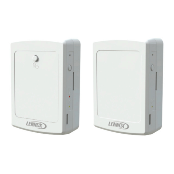
Sensor (21L07) LCS-5030 TMP/RH SENSOR CATALOG # 21L07 RESET button After Hour Override (AHO) enable switch BEACON enable button BATTERY status LED SIGNAL strength LED Air Circulation Vents Figure 2. Wireless Sensor Configuration (Factory Defaults) Label NOTE: Changed switch settings only take af- fect after a sensor power reset. -
Page 6: Sensor - Power Options
By itself with a controller (Wired Standalone) Line Power: When the wireless sensor is • • In a network with a Lennox Network Control powered by external line power (24VAC). Panel (NCP) • In a network with a third party BACnet Con- troller –... - Page 7 S -BUS OPERATION IN STANDALONE MODE The sensor can also function with a unit controller with an NCP/L-Connection System. The 21L07 is RTU BUS Address = 2 compatible in standalone or with an NCP with the following unit controllers: NOTE: Use 22AWG, one twisted pair shield cable •...
- Page 8 S-BUS OPERATIONS WITH NETWORK CONTROL PANEL (NCP) NOTE: Use 22AWG, 1 twisted pair shielded cable (100% aluminum shield with strain wire with Teflon™ jacket). Recommend Lennox catalog numbers 94L63, 27M19, 68M25 or Belden Type 88761 or equivalent. S-Bus Address = 1...
- Page 9 Setup NOTE: Lennox M3/M4 unit controllers use a de- fault S-BUS address of 2. If the sensor NOTE: The following S1 and S2 switches need and unit controller are both configured to be set before power is applied to the to use address 2, there is no need to go sensor.
- Page 10 Thermostat/ Return Air Backup and then select Next. then select SAVE. The summary is displayed and then se- NOTE: Lennox recommends selecting backup lect Next after checking the displayed mode (Return Air Backup). setting information. Finish the wizard and return to the main Select Finish.
- Page 11 S-BUS OPERATIONS WITH BACNET - WIRED BACNET NOTE: Use 22AWG, 1 twisted pair shielded cable (100% aluminum shield with strain wire with Teflon™ EXECUTIVE jacket). Recommend Lennox catalog numbers 94L63, 27M19, 68M25 or Belden Type 88761 or CONTROLLER equivalent. Drain...
-
Page 12: Sensor - Operation With Bacnet Network (M3/M4 Only)
5. For setup with the M4 Unit Controller use the with an BACnet Building Automation System following procedure: (BAS). The 21L07 is ONLY compatible in this mode Download the CORE Service app. of operation with M3 and M4 Unit Controllers. - Page 13 SAVE. This should match the S-BUS Ad- Cycling/Auto-Continuous1/2/3 and dress on switch S1 on the sensor. select Next. NOTE: Lennox M3/M4 unit controllers use a de- Select Backup Mode as None/Wired fault S-BUS address of 2. If the sensor Thermostat/ Return Air Backup and and unit controller are both configured then select Next.
-
Page 14: Sensor - Wiring Troubleshooting
NOTE: Lennox recommends setting a backup Select Backup Mode as None/Wired Thermostat/ Return Air Backup and mode (Return Air Backup). then select SAVE. Finish the wizard and return to the main menu. NOTE: Lennox recommends setting a backup mode (Return Air Backup). -
Page 15: Sensor - Wireless Installation Setup
Sensor – Wireless Installation Setup 2. Click Add node on the Network Nodes screen. This triggers the CORE Service App Wireless operation is ONLY compatible with M4 to scan for new sensors or repeaters. Unit Controller). To commission a wireless sensor, Press and hold for two seconds the “Beacon you must first pair the CORE Service App to the button”... -
Page 16: Sensor - Wireless Standalone
Sensor – Wireless Standalone Select S-Bus / Wireless Sensor under Network Setup Wizard and select Next. Standalone operation is a setup of one CORE Unit Leave the S-Bus address in its current Controller and up to five wireless sensors without setting and select Next. -
Page 17: Sensor - Placement And Confirming Location (Test)
Sensor – Placement and Confirming Table 1. Sensor LED Descriptions Location (Test) Signal Battery LED Indicator Description The wireless sensor has a test functionality to confirm placement of the sensor is acceptable Battery power is low, range of the RTU. To test the sensor placement: and sensor is out of Blinking for 10 Solid for 10... -
Page 18: Sensor - Wireless Checkout / Troubleshooting
Sensor – Wireless Checkout / Sensor – Low Battery Indication Troubleshooting The Battery LED will blink for 10 seconds when the This step may be required to verify whether added battery voltage drops below 20%. When used with wireless sensor is grouped and communicating an M4 Unit Controller an alarm will be activated. -
Page 19: Sensor - Data Verification
Sensor – Data Verification IMPORTANT This step may be required to verify whether added It is recommended that any sensors that are wireless sensor is grouped and communicating taken out of use should be removed from the with the rooftop unit. network and a hard reset performed. -
Page 20: Repeater (21L09)
2. Press and hold the Beacon button on the Repeater (21L09) wireless repeater for two seconds. 3. The user should be able to see the MAC ad- Repeater – 24VAC Line Power dress of wireless repeater on the CORE Ser- vice app. -
Page 21: Repeater - Signal Strength Alert Indication
3. Observe the status of the signal strength LED IMPORTANT (see Table 1. Sensor LED Descriptions on page 17). A maximum of five wireless repeaters can be added per RTU NOTE: Wait 5 to 20 seconds for the test to com- pete and observe the signal strength Repeater –... -
Page 22: Repeater - Network Removal And Reset
Repeater – Network Removal and Reset Repeater Hard Reset Use the following procedure to perform a factory This procedure will remove the specific wireless reset. repeater (relay) from the rooftop unit group. Use 1. Press and hold both the beacon and reset the following steps to perform the network removal buttons simultaneously for 10 seconds. -
Page 23: Repeater And Sensor Placement Requirements
Repeater and Sensor Placement Requirements Wireless sensors can also be used as repeaters if powered by external 24VAC. Wireless sensors operated on battery power cannot hop a signal to the next device, and therefore operate only as a temperature sensor. A maximum of two repeater hops are supported. SINGLE STORY BUILDING INSTALLATION NO REPEATER USED ROOT TOP UNIT... - Page 24 SINGLE STORY BUILDING INSTALLATION REPEATER OR SENSOR POWER BY 24VAC ROOT TOP UNIT (BLE ANTENNA INSTALLED IN ROOF RETURN AIR SECTION OF RTU) (Typcial construction - Corrugated Steel) MAXIMUM PENTRATION OF 1 ROOF, 1 CEILING/FLOOR AND TWO INTERIOR WALLS (TYPICAL) HOP 1 MAXIMUM DISTANCE BETWEEN RTU (M4/W4) AND REPEATER IS 80 FEET...
- Page 25 TWO STORY BUILDING INSTALLATION REPEATER OR SENSOR USING 24 VAC ROOT TOP UNIT (BLE ANTENNA INSTALLED IN ROOF RETURN AIR SECTION OF RTU) (Typcial construction - Corrugated Steel) MAXIMUM PENTRATION OF 1 ROOF, 1 CEILING/FLOOR AND TWO INTERIOR WALLS (TYPICAL) HOP 1 MAXIMUM DISTANCE BETWEEN MAXIMUM DISTANCE BETWEEN...
-
Page 26: Fcc Compliance Statement
encouraged to try to correct the interference FCC Compliance Statement by one of the following measures: • Reorient or relocate the receiving an- PART 15.19 This device complies with Part 15 tenna. of the FCC Rules. Operation is subject to the •...
Need help?
Do you have a question about the 21L07 and is the answer not in the manual?
Questions and answers