Lennox LCH Series Installation Instructions Manual

Lennox LCH Series Installation Instructions Manual

Gas and cooling packaged units
Hide thumbs Also See for LCH Series:

Advertisement

©2019
WARNING
Improper installation, adjustment, alteration, ser­
vice or maintenance can cause property damage,
personal injury or loss of life. Installation and ser­
vice must be performed by a licensed professional
HVAC installer or equivalent, service agency, or the
gas supplier

Table Of Contents

. . . . . . . . . . . . . . . . . . . . . . . . . . . . . . . . .
. . . . . . . . . . . . . . . . . . . . . . . . .
. . . . . . . . . . . . . . . . . . . .
. . . . . . . . . . . . . . . . . . . . . . . . . . . . . . . . . . . .
. . . . . . . . . . . . . . . . . . . . . . . . . . . . . . .
. . . . . . . . . . . . . . . . . . . . . . . . . . . . . . . .
. . . . . . . . . . . . . . . . . . . . . . . . . . . .
. . . . . . . . . . . . . . . . . . . . . . .
. . . . . . . . . . . . . . . . . . . . . .
. . . . . . . . . . . . . . . . . . . . . . . . . .
. . . . . . . . . . . . . . . . . . . . . . . . . . . . . . . . .
. . . . . . . . . . . . . . . . . . . . .
RETAIN THESE INSTRUCTIONS FOR FUTURE REFERENCE
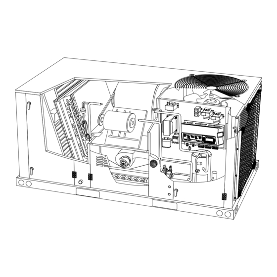
LG STANDARD AND HIGH EFFICIENCY SHOWN
INSTALLATION
INSTRUCTIONS
LGH/LCH036, 048,
060, 072 & 074
3, 4, 5 and 6 Ton
GAS AND COOLING PACKAGED UNITS
507410-05
4/2019
Supersedes 10/2018
Page 2
Page 3
Page 5
Page 5
Page 5
. . . . . . . . . . . . . . . . . . . . . . . . . . . . . . . . . . . .
Page 6
Page 6
Page 7
Page 7
Page 7
As with any mechanical equipment, contact with
Page 9
sharp sheet metal edges can result in personal in­
jury. Take care while handling this equipment and
Page 10
wear gloves and protective clothing.
. . . . . . . . . . . . . . . . . . . . . . . . .
. . . . . . . . . . . . . . . . . . . . . . .
. . . . . . . . . . . .
. . . . . . . . . . . . . . . . . . . . . . . . . . . .
. . . . . . . . . . . . . . . . . . . . . . . . . . .
. . . . . . . . . . . . . . . . . . . . . . . . . . .
. . . . . . . . . . . .
. . . . . . . . . . . . . . . . . . . . . . . .
. . . . . . . . . . . .
. . . . . . . . . . . . . . . . . . . . . .
. . . . . . . . . . . . . . .
CAUTION
Page 10
Page 11
Page 13
Page 46
Page 57
Page 60
Page 61
Page 62
Page 62
Page 65
Page 67
Page 70

Advertisement

Table of Contents
loading
Need help?

Need help?

Do you have a question about the LCH Series and is the answer not in the manual?

Questions and answers

Summary of Contents for Lennox LCH Series

  • Page 1: Table Of Contents

    ©2019 INSTALLATION INSTRUCTIONS WARNING LGH/LCH036, 048, Improper installation, adjustment, alteration, ser­ 060, 072 & 074 vice or maintenance can cause property damage, personal injury or loss of life. Installation and ser­ 3, 4, 5 and 6 Ton vice must be performed by a licensed professional HVAC installer or equivalent, service agency, or the GAS AND COOLING PACKAGED UNITS gas supplier...
  • Page 2: Dimensions

    LGH/LCH036, 048, 060, 072 & 074 DIMENSIONS in. - Gas heat section shown 5−5/8 16−1/4 (143) (279) (413) (457) 5 (127) 7 (178) BOTTOM RETURN OPENING BOTTOM (508) SUPPLY (737) 47 (1194) OPENING BASE CENTER 25−3/4 (654) GRAVITY 9−1/2 6−5/8 (241) (168) 26−1/2...
  • Page 3: Parts Arrangements

    LGH036, 048, 060S, H & 072, 074H PARTS ARRANGEMENT EVAPORATOR BLOWER REHEAT COIL COIL FILTERS (4) MOTOR (OPTIONAL) 036, 048:16 X 20 X 2” CONDENSER (BELT DRIVE SHOWN) 060, 072, 074: 20 X 20 X 2” ECONOMIZER (OPTIONAL) BLOWER COIL GUARDS (OPTIONAL) CONDENSER...
  • Page 4 LGH036, 048, 060, 074U PARTS ARRANGEMENT EVAPORATOR FILTERS (4) COIL 20 X 20 X 2” CONDENSER ECONOMIZER (OPTIONAL) BLOWER COIL GUARDS (OPTIONAL) CONDENSER COIL CONDENSATE DRAIN COMPRESSOR GAS VALVE 1 (4-STG. GAS BURNERS HEAT SHOWN) GAS VALVE 2 COMBUSTION UNIT (4-STG.
  • Page 5: Shipping And Packing List

    Shipping and Packing List WARNING Package 1 of 1 contains: 1- Assembled unit Electric shock hazard and danger of Check unit for shipping damage. Receiving party should explosion. Can cause injury, death or product or property damage. Turn off contact last carrier immediately if shipping damage is found. gas and electrical power to unit before General performing...
  • Page 6: Unit Support

    Use of this unit as a construction heater or air conditioner 3- Duct must be attached to the roof mounting frame is not recommended during any phase of construction. and not to the unit; supply and return plenums must Very low return air temperatures, harmful vapors and be installed before setting the unit.
  • Page 7: Rigging Unit For Lifting

    Rigging Unit For Lifting UNIT SUPPLY AND RETURN AIR OPENINGS HORIZONTAL Rig unit for lifting by attaching four cables to holes in unit SUPPLY AIR HORIZONTAL base rail. See figure 2. OPENING RETURN AIR OPENING 1- Detach wooden base protection before rigging. 2- Remove all six base protection brackets before setting unit.
  • Page 8 Two hinge screws must be removed in addition to the CONDENSATE SIDE DRAIN CONNECTION mullion screws. See figure 8. CAULK AROUND CONDENSATE COUPLING UNITS WITH HINGED PANELS NOTE - Allow clearance to open doors when installing CONDENSATE UNIT DRAIN MULLION condensate piping.
  • Page 9: Gas Piping

    When making piping connections a drip leg should be BOTTOM CONDENSATE DRAIN installed on vertical pipe runs to serve as a trap for CAUTION: Be careful not to sediment or condensate. A 1/8” N.P.T. plugged tap is damage the coupling threads located on gas valve for test gauge connection.
  • Page 10: Pressure Test Gas Piping

    NOTE-In case emergency shut down is required, turn off BOTTOM ENTRY GAS PIPING COMPLETED the main manual shut-off valve and disconnect main power to unit. These devices should be properly labeled TO GAS GROUND VALVE by the installer. JOINT UNION PRESSURE TEST GAS LINE STREET ELBOW...
  • Page 11: Electrical Connections

    B-Control Wiring Electrical Connections The Unit Controller will operate the unit from a POWER SUPPLY thermostat or zone sensor based on the System Mode. The default System Mode is the thermostat mode. Refer Do not apply power or close disconnect switch until installation is complete.
  • Page 12 FIELD WIRING WITH ELECTRONIC AND ELECTRO-MECHANICAL THERMOSTATS (Thermostat Mode) 24 V POWER P297 J297A TO UNIT CONTROLLER THERMOSTAT INPUTS TO R TO G K55−1 TO Y1 OTHER THERMOSTAT SIGNALS REMAIN CONNECTED AS SHOWN ON THE RIGHT. TO PROVIDE SUPERMARKET REHEAT SCHEME USE S86 DEHUMIDISTAT AND K55.
  • Page 13: Blower Operation And Adjustments

    Wire runs over 150 feet (mm): Blower Operation and Adjustments Use a local, isolated 24VAC transformer such as Lennox cat #18M13 (20VA minimum) to supply power Units are equipped with one of three factory-installed to RH sensor as shown in figure 17. Use two shielded cables containing 20AWG minimum, twisted pair blower options.
  • Page 14 A-Blower Operation TABLE 4 MINIMUM AIRFLOW-LCH UNITS WITH ELECTRIC HEAT (DIRECT DRIVE) Refer to the Unit Controller Installation and Setup Guide to energize blower. Use the menu navigation arrows and Downflow & Horizontal Airflow select button; see SERVICE > TEST. LCH036H, U 1080 LCH048H, U...
  • Page 15 D-Adjusting Unit CFM - Ultra High Efficiency Direct blower calibration status is displayed as a % complete. Drive Blowers Upon successful completion, the Unit Controller will display CALIBRATION SUCCESS and go back to the The supply CFM can be adjusted by changing Unit blower calibration screen.
  • Page 16 TABLE 6 036, 048, 060H DIRECT DRIVE PARAMETER SETTINGS LGH/LCH Unit Factory Default Settings Parameter Field Setting Description 036 H4E 048 H4E 060 H4E 036-060 S4T SETUP > TEST & BALANCE > BLOWER Percentage torque for indoor HIGH SPEED Not Applicable blower high speed.
  • Page 17 D-Adjusting Unit CFM - Belt Drive Blowers PULLEY ALIGNMENT ALIGNED The blower RPM can be adjusted at the motor pulley. Loosen Allen screw and turn adjustable pulley clockwise to increase CFM. Turn counterclockwise to decrease CFM. See figure 21. Do not exceed minimum and MOTOR BLOWER BELT...
  • Page 18 G-Check Belt Tension ADJUST BELT TENSIONER Overtensioning belts shortens belt and bearing life. INDICATOR SHOULD BE MAXIMUM BETWEEN MINIMUM AND Check belt tension as follows: TENSION MAXIMUM TENSION LINES 1- Measure span length X. See figure 22. 2- Apply perpendicular force to center of span (X) with MINIMUM enough pressure to deflect belt 1/64”...
  • Page 19 INSTALL BELT DRIVER TENSIONER PULLEY DRIVEN PULLEY ROTATE DRIVEN PULLEY TO SEAT BELT FIGURE 24 Page 19 LGH/LCH036, 048, 060, 072, 074...
  • Page 20 Page 20...
  • Page 21 Page 21...
  • Page 22 Page 22...
  • Page 23 Page 23...
  • Page 24 Page 24...
  • Page 25 Page 25...
  • Page 26 BLOWER DATA - LGH BELT DRIVE - 3 TON - STANDARD EFFICIENCY BLOWER TABLE INCLUDES RESISTANCE FOR BASE UNIT ONLY WITH DRY INDOOR COIL AND AIR FILTERS IN PLACE. FOR ALL UNITS ADD: 1 - Any factory installed options air resistance (heat section, economizer, etc.). 2 - Any field installed accessories air resistance (duct resistance, diffuser, etc.).
  • Page 27 BLOWER DATA - LGH BELT DRIVE - 3 TON - STANDARD EFFICIENCY BLOWER TABLE INCLUDES RESISTANCE FOR BASE UNIT ONLY WITH DRY INDOOR COIL AND AIR FILTERS IN PLACE. FOR ALL UNITS ADD: 1 - Any factory installed options air resistance (heat section, economizer, etc.). 2 - Any field installed accessories air resistance (duct resistance, diffuser, etc.).
  • Page 28 BLOWER DATA - LCH BELT DRIVE - 3 TON - STANDARD EFFICIENCY BLOWER TABLE INCLUDES RESISTANCE FOR BASE UNIT ONLY WITH DRY INDOOR COIL AND AIR FILTERS IN PLACE. FOR ALL UNITS ADD: 1 - Any factory installed options air resistance (heat section, economizer, etc.). 2 - Any field installed accessories air resistance (duct resistance, diffuser, etc.).
  • Page 29 BLOWER DATA - LCH BELT DRIVE - 3 TON - STANDARD EFFICIENCY BLOWER TABLE INCLUDES RESISTANCE FOR BASE UNIT ONLY WITH DRY INDOOR COIL AND AIR FILTERS IN PLACE. FOR ALL UNITS ADD: 1 - Any factory installed options air resistance (heat section, economizer, etc.). 2 - Any field installed accessories air resistance (duct resistance, diffuser, etc.).
  • Page 30 BLOWER DATA - LGH BELT DRIVE - 4 TON - STANDARD EFFICIENCY BLOWER TABLE INCLUDES RESISTANCE FOR BASE UNIT ONLY WITH DRY INDOOR COIL AND AIR FILTERS IN PLACE. FOR ALL UNITS ADD: 1 - Any factory installed options air resistance (heat section, economizer, etc.). 2 - Any field installed accessories air resistance (duct resistance, diffuser, etc.).
  • Page 31 BLOWER DATA - LGH BELT DRIVE - 4 TON - STANDARD EFFICIENCY BLOWER TABLE INCLUDES RESISTANCE FOR BASE UNIT ONLY WITH DRY INDOOR COIL AND AIR FILTERS IN PLACE. FOR ALL UNITS ADD: 1 - Any factory installed options air resistance (heat section, economizer, etc.). 2 - Any field installed accessories air resistance (duct resistance, diffuser, etc.).
  • Page 32 BLOWER DATA - LCH BELT DRIVE - 4 TON - STANDARD EFFICIENCY BLOWER TABLE INCLUDES RESISTANCE FOR BASE UNIT ONLY WITH DRY INDOOR COIL AND AIR FILTERS IN PLACE. FOR ALL UNITS ADD: 1 - Any factory installed options air resistance (heat section, economizer, etc.). 2 - Any field installed accessories air resistance (duct resistance, diffuser, etc.).
  • Page 33 BLOWER DATA - LCH BELT DRIVE - 4 TON - STANDARD EFFICIENCY BLOWER TABLE INCLUDES RESISTANCE FOR BASE UNIT ONLY WITH DRY INDOOR COIL AND AIR FILTERS IN PLACE. FOR ALL UNITS ADD: 1 - Any factory installed options air resistance (heat section, economizer, etc.). 2 - Any field installed accessories air resistance (duct resistance, diffuser, etc.).
  • Page 34 BLOWER DATA - BELT DRIVE - 5 TON BLOWER TABLE INCLUDES RESISTANCE FOR BASE UNIT ONLY WITH DRY INDOOR COIL AND AIR FILTERS IN PLACE. FOR ALL UNITS ADD: 1 - Any factory installed options air resistance (heat section, economizer, etc.). 2 - Any field installed accessories air resistance (duct resistance, diffuser, etc.).
  • Page 35 BLOWER DATA - LGH BELT DRIVE - 5 TON - STANDARD EFFICIENCY BLOWER TABLE INCLUDES RESISTANCE FOR BASE UNIT ONLY WITH DRY INDOOR COIL AND AIR FILTERS IN PLACE. FOR ALL UNITS ADD: 1 - Any factory installed options air resistance (heat section, economizer, etc.). 2 - Any field installed accessories air resistance (duct resistance, diffuser, etc.).
  • Page 36 BLOWER DATA - LCH BELT DRIVE - 5 TON - HIGH EFFICIENCY BLOWER TABLE INCLUDES RESISTANCE FOR BASE UNIT ONLY WITH DRY INDOOR COIL AND AIR FILTERS IN PLACE. FOR ALL UNITS ADD: 1 - Any factory installed options air resistance (heat section, economizer, etc.). 2 - Any field installed accessories air resistance (duct resistance, diffuser, etc.).
  • Page 37 BLOWER DATA - LCH BELT DRIVE - 5 TON - HIGH EFFICIENCY BLOWER TABLE INCLUDES RESISTANCE FOR BASE UNIT ONLY WITH DRY INDOOR COIL AND AIR FILTERS IN PLACE. FOR ALL UNITS ADD: 1 - Any factory installed options air resistance (heat section, economizer, etc.). 2 - Any field installed accessories air resistance (duct resistance, diffuser, etc.).
  • Page 38 BLOWER DATA - LGH BELT DRIVE - 6 TON - HIGH EFFICIENCY BLOWER TABLE INCLUDES RESISTANCE FOR BASE UNIT ONLY WITH DRY INDOOR COIL AND AIR FILTERS IN PLACE. FOR ALL UNITS ADD: 1 - Any factory installed options air resistance (heat section, economizer, etc.). 2 - Any field installed accessories air resistance (duct resistance, diffuser, etc.).
  • Page 39 BLOWER DATA - LGH BELT DRIVE - 6 TON - HIGH EFFICIENCY BLOWER TABLE INCLUDES RESISTANCE FOR BASE UNIT ONLY WITH DRY INDOOR COIL AND AIR FILTERS IN PLACE. FOR ALL UNITS ADD: 1 - Any factory installed options air resistance (heat section, economizer, etc.). 2 - Any field installed accessories air resistance (duct resistance, diffuser, etc.).
  • Page 40 BLOWER DATA - LCH BELT DRIVE - 6 TON - HIGH EFFICIENCY BLOWER TABLE INCLUDES RESISTANCE FOR BASE UNIT ONLY WITH DRY INDOOR COIL AND AIR FILTERS IN PLACE. FOR ALL UNITS ADD: 1 - Any factory installed options air resistance (heat section, economizer, etc.). 2 - Any field installed accessories air resistance (duct resistance, diffuser, etc.).
  • Page 41 BLOWER DATA - LCH BELT DRIVE - 6 TON - HIGH EFFICIENCY BLOWER TABLE INCLUDES RESISTANCE FOR BASE UNIT ONLY WITH DRY INDOOR COIL AND AIR FILTERS IN PLACE. FOR ALL UNITS ADD: 1 - Any factory installed options air resistance (heat section, economizer, etc.). 2 - Any field installed accessories air resistance (duct resistance, diffuser, etc.).
  • Page 42 Page 42...
  • Page 43 Page 43...
  • Page 44 Page 44...
  • Page 45 BLOWER DATA BELT DRIVE KIT SPECIFICATIONS - 036-074 Model Motor HP No. of Drive Kits and RPM Range Speeds Nominal Maximum 0.75 0.86 low 449-673 - - - - - - - - - - - - - - - high 673-1010 1.15 - - -...
  • Page 46: Cooling Start-Up

    TABLE 9 MANUFACTURER'S DRIVE COMPONENT NUMBERS DRIVE COMPONENTS Motor Pulley Blower Pulley Belt Drive No. Supplier No. OEM Part No. Supplier No. OEM Part No. Supplier No. OEM Part No. 1VP34x7/8 31K6901 AK54 x 1 100244-19 100245-17 1VP34x7/8 31K6901 AK49 x 1 100244-18 100245-16 1VP34x7/8...
  • Page 47 If pressure differential is not observed or blower rotation is Check unit components if there are significant not correct: differences. 3- Disconnect all remote electrical power supplies. 3- Measure the outdoor ambient temperature and the 4- Reverse any two field-installed wires connected to suction pressure.
  • Page 48 TABLE 11 LGH/LCH036S/H REHEAT NORMAL OPERATING PRESSURES - ALL-ALUMINUM COIL Outdoor Coil Entering Air Temperature 65 °F 75 °F 85 °F 95 °F 105 °F 115 °F Suct Disc Suct Disc Suct Disc Suct Disc Suct Disc Suct Disc (psig) (psig) (psig) (psig)
  • Page 49 TABLE 16 LGH/LCH072H NORMAL OPERATING PRESSURES - ALL-ALUMINUM COIL Outdoor Coil Entering Air Temperature 65 °F 75 °F 85 °F 95 °F 105 °F 115 °F Suct Disc Suct Disc Suct Disc Suct Disc Suct Disc Suct Disc (psig) (psig) (psig) (psig) (psig)
  • Page 50 LGH/LCH036S/H CHARGING CURVE - ALL-ALUMINUM COIL Outdoor Temperature (°F) 115° 105° 95° 85° 75° 65° Suction Pressure (psig) LGH/LCH036S/H REHEAT CHARGING CURVE - ALL-ALUMINUM COIL Outdoor Temperature (°F) 115° 105° 95° 85° 75° 65° Suction Pressure (psig) Page 50 LGH/LCH036, 048, 060, 072, 074...
  • Page 51 LGH/LCH048S/H CHARGING CURVE - ALL-ALUMINUM COIL Outdoor Temperature (°F) 115° 105° 95° 85° 75° 65° Suction Pressure (psig) LGH/LCH048S/H REHEAT CHARGING CURVE - ALL-ALUMINUM COIL Outdoor Temperature (°F) 115° 105° 95° 85° 75° 65° Suction Pressure (psig) Page 51 LGH/LCH036, 048, 060, 072, 074...
  • Page 52 LGH/LCH060S/H CHARGING CURVE - ALL-ALUMINUM COIL Outdoor Temperature (°F) 115° 105° 95° 85° 75° 65° Suction Pressure (psig) LGH/LCH060S/H REHEAT CHARGING CURVE - ALL-ALUMINUM COIL Outdoor Temperature (°F) 115° 105° 95° 85° 75° 65° Suction Pressure (psig) Page 52 LGH/LCH036, 048, 060, 072, 074...
  • Page 53 LGH/LCH072H CHARGING CURVE - ALL-ALUMINUM COIL Outdoor Temperature (°F) 115° 105° 95° 85° 75° 65° Suction Pressure (psig) LGH/LCH072H REHEAT CHARGING CURVE - ALL-ALUMINUM COIL Outdoor Temperature (°F) 115° 105° 95° 85° 75° 65° Suction Pressure (psig) Page 53 LGH/LCH036, 048, 060, 072, 074...
  • Page 54 LGH/LCH074H CHARGING CURVE - ALL-ALUMINUM COIL Outdoor Temperature (°F) 115° 105° 95° 85° 75° 65° Suction Pressure (psig) LGH/LCH074H REHEAT CHARGING CURVE - ALL-ALUMINUM COIL Outdoor Temperature (°F) 115° 105° 95° 85° 75° 65° Suction Pressure (psig) Page 54 LGH/LCH036, 048, 060, 072, 074...
  • Page 55 D-Refrigerant Charge and Check - Fin/Tube Coil 3- The approach method is not valid for grossly over or undercharged systems. Use tables 20 through 32 as WARNING-Do not exceed nameplate charge under a guide for typical operating pressures. any condition. This unit is factory charged and should require no further Subcooling Method - Ultra High Efficiency Units adjustment.
  • Page 56 TABLE 23 TABLE 28 LG/LC 048S/H NORMAL OPERATING PRESSURES LG/LC 060U NORMAL OPERATING PRESSURES Outdoor Coil Discharge Suction + 5 Outdoor Coil Discharge Suction + 5 Entering Air Temp +10 psig psig Entering Air Temp +10 psig psig 655 F 655 F 755 F 755 F...
  • Page 57: Cooling Operation

    TABLE 33 6- Discharge Line Thermostat (S40) APPROACH TEMPERATURE 3 through 5 Ton Non-Ultra Units Only Switch opens when discharge line temperature Liquid Temp. Minus LGH/LCH Unit Ambient Temp. reaches 94_F+5 (34_C+3) and closes when temperature falls below 74_F+5 (23_C+3). Prevents 036S &...
  • Page 58 B-Three-Stage Thermostat OR Room Sensor 036U, 048U, 060U, 074U UNITS A-Two-Stage Thermostat 1-Economizer With Outdoor Air Suitable 1-Economizer With Outdoor Air Suitable Y1 Demand - Y1 Demand - Compressors Off Compressor Off Blower Cooling Low Blower Low Dampers modulate Dampers modulate Y2 Demand - Y2 Demand - Compressor Low...
  • Page 59 C-Zone Sensor D-Verify Proper Operation In Zone Sensor Mode 1-Economizer With Outdoor Air Suitable The Unit Controller (A55) communicates the appropriate Low Cooling Demand - frequency (speed) to the compressor inverter (A192) to Compressor Off match the cooling load. Because the cooling load varies, Blower Variable the Unit Controller provides a test mode to initiate a Dampers Modulate...
  • Page 60: Gas Heat Start-Up

    This unit is equipped with an automatic spark ignition Gas Heat Start-Up (Gas Units) system. There is no pilot. In case of a safety shutdown, move thermostat switch to OFF and return the thermostat FOR YOUR SAFETY READ BEFORE LIGHTING switch to HEAT to reset ignition control.
  • Page 61: Heating Operation And Adjustments

    5- Move gas valve switch to OFF. See figure 25 or 26. Heating Operation and Adjustments (Gas Units) 6- Wait five (5) minutes to clear out any gas. If you then smell gas, STOP! Immediately call your A-Heating Sequence of Operation gas supplier from a neighbor's phone.
  • Page 62: Electric Heat Start-Up

    9- While a W1 demand is present, 2 -stage will operate Electric Heat Start-Up (LCH Units) indefinitely. 10- Once a W2 demand is applied with 2 -stage active, Optional electric heat will stage on and cycle with power is supplied to the A3 ignition control. thermostat demand.
  • Page 63 CALIBRATION. Push SAVE to start calibration. The B­Enter Supply Air CFM Into Unit Controller blower calibration status is displayed as a % complete. Use the following menu path to enter each supply air CFM Upon successful completion, the Unit Controller will into the Unit Controller.
  • Page 64 TABLE 37 MINIMUM / MAXIMUM CFM LGH/LCH036-060H Unit Parameter Settings LCH/LGH Default Factory Settings Parameter Name 036H4E 048H4E 060H4E SETUP > TEST & BALANCE > BLOWER COOLING HI SPEED / HEATING MAXIMUM (480 CFM/TON) 1440 1920 2400 COOLING HI SPEED MINIMUM (280 CFM/TON) 1120 1400 COOLING LOW SPEED MINIMUM (220 CFM/TON)
  • Page 65: Hot Gas Reheat Startup

    Reheat Setpoint SCR Electric Heat Controller (LCH Units) Reheat is factory-set to energize when indoor relative Optional factory-installed SCR (A38) will provide small humidity rises above 60% (default). The reheat setpoint amounts of power to the electric heat elements to can be adjusted by changing Unit Controller Settings - efficiently maintain warm duct air temperatures when Control menu.
  • Page 66 REHEAT MODE REFRIGERANT ROUTING RETURN OUTDOOR EVAPORATOR EXPANSION COIL VALVE REHEAT COIL SUPPLY COMPRESSOR CONDENSER COIL CHECK VALVE REHEAT VALVE FIGURE 28 COOLING MODE REFRIGERANT ROUTING RETURN OUTDOOR EVAPORATOR EXPANSION COIL VALVE REHEAT COIL SUPPLY COMPRESSOR CONDENSER COIL CHECK VALVE REHEAT VALVE FIGURE 29...
  • Page 67: Service

    Service REMOVE FILTERS The unit should be inspected once a year by a qualified service technician. CAUTION Label all wires prior to disconnection when servic­ ing controls. Wiring errors can cause improper and dangerous operation. Verify proper operation after servicing. PULL TO REMOVE FILTERS...
  • Page 68 IGNITOR BURNER BOX ASSEMBLY Single- and Two-Stage SPARK GAP SHOULD BE 1/8” (3mm) REMOVE INDIVIDUAL BURNERS ON OLDER UNITS; REMOVE THE ENTIRE BURNER ASSEMBLY ON NEWER UNITS. FLAME SENSOR FIGURE 33 8- Restore electrical power and gas supply. Follow lighting instructions attached to unit and use inspection port in access panel to check flame.
  • Page 69 D-Combustion Air Inducer (Gas Units) 7- Replace mullion. A combustion air proving switch checks combustion air 8- Clean combustion air inlet louvers on blower access inducer operation before allowing power to the gas panel using a small brush. controller. Gas controller will not operate if inducer is E-Flue Box (Gas Units) obstructed.
  • Page 70: Factory Unit Controller Settings

    CLEAN CONDENSER COIL - UNITS WITH FIN/TUBE COILS ENDPLATE IS SECURED TO MULLION TOP VIEW Remove unit top panel and condenser section access panel. Remove screws securing coil end plate to mullion. Remove wire ties connecting coils slabs and separate SUPPLY slabs 3-4”...
  • Page 71 A34 Pressure Sensor = C [5] Network Module A34 Pressure Sensor with N = Not Installed Enable Switch = D B = BACnet S27 and S39 Pressure L = LonTalk (Lennox) Switch = E FIGURE 38 Page 71 LGH/LCH036, 048, 060, 072, 074...
  • Page 72 Installed on DI-3 = 3 [5] Phase / Voltage Detection * N = Not Installed 1 = Enabled Internal (Lennox) 2 = External (A42) Phase Detection * When Phase / Voltage detection monitoring is enabled on a three-phase on DI-2 system and configured incorrectly will result in the system going into de­...

Table of Contents