Table of Contents
Advertisement
Quick Links
VENT-FREE GAS WALL
HEATER
OWNER'S OPERATION AND
INSTALLATION MANUAL
BLUE FLAME MODELS
LRT10B-LP, LRT10B-NG
LRT20B-LP, LRT20B-NG
LRT30B-LP, LRT30B-NG
WARNING: If the information in this manual is not
followed exactly, a fire or explosion may result causing
property damage, personal injury or loss of life.
— Do not store or use gasoline or other flammable va-
pors and liquids in the vicinity of this or any other
appliance.
— WHAT TO DO IF YOU SMELL GAS
• Do not try to light any appliance.
• Do not touch any electrical switch; do not use any
phone in your building.
• Immediately call your gas supplier from a neighbor's
phone. Follow the gas supplier's instructions.
• If you cannot reach your gas supplier, call the fire
department.
— Installation and service must be performed by a quali-
fied installer, service agency or the gas supplier.
INSTALLER: Leave this manual with the appliance.
CONSUMER: Retain this manual for future reference.
Questions, problems, missing parts? Before returning to your retailer, call
our customer service department at 1-866-573-0674, 7:30 am - 4:15 pm CST,
Monday through Friday or email customerservice@usaprocom.com
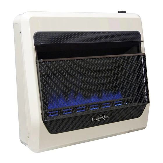
30,000 BTU/Hr
Model Shown
Advertisement
Table of Contents

Related Manuals for Procom LOST Piver LRT10B-LP


Summary of Contents for Procom LOST Piver LRT10B-LP
- Page 1 30,000 BTU/Hr Model Shown VENT-FREE GAS WALL HEATER OWNER’S OPERATION AND INSTALLATION MANUAL BLUE FLAME MODELS LRT10B-LP, LRT10B-NG LRT20B-LP, LRT20B-NG LRT30B-LP, LRT30B-NG WARNING: If the information in this manual is not followed exactly, a fire or explosion may result causing property damage, personal injury or loss of life.
-
Page 2: Table Of Contents
TABLE OF CONTENTS Safety ............3 Operation ..........16 Qualified Installing Agency ......4 Inspecting Burners........18 Specifications ..........5 Care And Maintenance ......19 Product Features ........6 Troubleshooting ........20 Local Codes..........6 Service Hints ........... 22 Preparing For Installation ......6 Replacement Parts ........ -
Page 3: Safety
SAFETY IMPORTANT: Read this owner’s WARNING: Any change to manual carefully and completely this heater or its controls can before trying to assemble, op- be dangerous. erate, or service this heater. Improper use of this heater can WARNING: Do not use any cause serious injury or death accessories not approved for from burns, fire, explosion,... -
Page 4: Qualified Installing Agency
SAFETY 1. Do not place Propane/LP supply tank(s) • Under dusty conditions. inside any structure. Propane/LP supply 7. Before using furniture polish, wax, carpet tank(s) must be placed outdoors. cleaner, or similar products, turn heater off. If heated, the vapors from these prod- 2. -
Page 5: Specifications
SPECIFICATIONS MODEL LRT10B-NG LRT10B-LP Ignition Piezo Piezo Gas Type Natural Propane/LP Maximum Input Rating 10,000 BTU/Hr 10,000 BTU/Hr Minimum Input Rating 5,000 BTU/Hr 5,000 BTU/Hr Pressure Regulator Setting 4" W.C. 9" W.C. Max 10.5" Max 14" Inlet Gas Pressure* (inches of water) Min 5"... -
Page 6: Product Features
PRODUCT FEATURES SAFETY PILOT THERMOSTATIC CONTROL This heater has a pilot with an Oxygen Deple- These heaters have a control valve with a tion Sensing (ODS) safety shutoff system. The thermostat sensing bulb. This results in the ODS/pilot shuts off the heater if there is not greatest heater comfort and may result in enough fresh air. -
Page 7: Unpacking
UNPACKING 1. Remove heater from carton. 3. Check heater for any shipping damage. If heater is damaged, promptly inform dealer 2. Remove all protective packaging applied where you bought heater. to heater for shipping WATER VAPOR: A BY-PRODUCT OF UNVENTED ROOM HEATERS Water vapor is a by-product of gas combus- The following steps will help ensure that water tion. - Page 8 AIR FOR COMBUSTION AND VENTILATION VENTILATION AIR Ventilation Air From Inside Building Ventilation Air From Outdoors Provide extra fresh air by using ventilation This fresh air would come from an adjoining grills or ducts. You must provide two perma- unconfined space. When ventilating to an nent openings: one within 12"...
-
Page 9: Installation
INSTALLATION IMPORTANT: Vent-free heaters add moisture NOTICE: This heater is intended to the air. Although this is beneficial, installing for use as supplemental heat. heater in rooms without enough ventilation air Use this heater along with your may cause mildew to form too much moisture. primary heating system. - Page 10 INSTALLATION INSTALLING THERMOSTAT SENSING BULB (OPTIONAL) 1. Pull out the sensing bulb from the two clips located in the shipping position. There is no need to take out the two bulb clips. 2. Take out the bulb clip from the hardware package and insert it into the square hole.
- Page 11 INSTALLATION Attaching to Wall Stud Method 2. Mark screw locations on wall (see Fig- ure 7). Note: Mark only last hole on each For attaching mounting bracket to wall studs: end of mounting bracket. Insert mounting 1. Drill holes at marked locations using 9/64" screws through these holes only.
- Page 12 INSTALLATION Placing Heater On Mounting 5. Replace heater onto mounting bracket. Bracket 6. Place spacers between bottom mounting 1. Locate two horizontal slots on back panel holes and wall anchor or drilled hole. of heater (see Figure 10). 7. Hold spacer in place with one hand. With other 2.
- Page 13 INSTALLATION CONNECTING TO GAS SUPPLY WARNING: A qualified ser- CAUTION: For propane/LP vice technician must connect gas, Never connect heater directly to the gas supply. This heater heater to gas supply. Follow all requires an external regulator local codes. (not supplied). Install the external WARNING: This appliance regulator between the heater and requires a 3/8"...
- Page 14 INSTALLATION Apply pipe joint sealant lightly to male threads. as shown in Figure 13. Pointing the vent down This will prevent excess sealant from going protects it from freezing rain or sleet. into pipe. Excess sealant in pipe could result Install sediment trap in supply line as shown in clogged heater valves.
- Page 15 INSTALLATION CHECKING GAS CONNECTIONS WARNING: Test all gas piping WARNING: Never use an open and connections for leaks after flame to check for a leak. Apply a installing or servicing. Correct mixture of liquid soap and water all leaks at once. to all joints.
-
Page 16: Operation
INSTALLATION PRESSURE TESTING HEATER GAS CONNECTIONS 1. Open equipment shutoff valve (see Fig- 5. Correct all leaks at once. ure 14, page 15). 6. Light heater (see Lighting Instructions 2. Open gas supply tank valve. below). Check all other internal joints for leaks. - Page 17 OPERATION Note: The first time that the heater is oper- 7. Keep control knob pressed in for 30 seconds after lighting pilot. After 30 ated after connecting the gas supply,the control knob should be pressed for about seconds, release control knob. If control knob does not pop up when released, thirty (30) seconds.
-
Page 18: Inspecting Burners
INSPECTING BURNERS IMPORTANT: Owner’s should check pilot flame pattern and burner flame pattern often. Incorrect flame patterns indicate the need for cleaning (see Care and Maintenance, page 19) or service. WARNING: Only a qualified service person should service and repair heater. This includes maintenance requiring replacement or alteration of components. -
Page 19: Care And Maintenance
CARE AND MAINTENANCE WARNING: Turn off heater and let cool before servicing. CAUTION: You must keep control areas, burner, and circulating air passageways of heater clean. Inspect these areas of heater before each use. Have heater inspected yearly by a qualified service techni- cian. -
Page 20: Troubleshooting
TROUBLESHOOTING WARNING: If you smell gas: • Shut off gas supply. • Do not try to light any appliance. • Do not touch any electrical switch; do not use any phone in your building. • Immediately call your gas supplier from a neighbor’s phone. Fol- low the gas supplier’s instructions. - Page 21 TROUBLESHOOTING Problem Possible Cause Corrective Action ODS/pilot lights but flame 1. Control knob is not fully 1. Press in control knob fully. goes out when control pressed in. knob is released. 2. Control knob is not pressed 2. After ODS/pilot lights, keep in long enough.
-
Page 22: Service Hints
TROUBLESHOOTING Problem Possible Cause Corrective Action Heater produces a whis- 1. Turning control knob to high 1. Turn control knob to low (1) tling noise when burner (5) position when burner is position and let warm up for is lit. cold. -
Page 23: Replacement Parts
When calling, please have your model and serial numbers of your heater ready. ACCESSORIES Purchase these heater accessories from your local dealer. If they can not supply these acces- sories, contact ProCom Heating, Inc. at 1-866-573-0674 for information. FLOOR MOUNTING EQUIPMENT SHUTOFF... -
Page 24: Parts
PARTS MODELS LRT10B-NG AND LRT10B-LP www.usaprocom.com 200403-01A... - Page 25 PARTS MODELS LRT10B-NG AND LRT10B-LP This list contains replaceable parts for your heater. When ordering replacement parts, follow the instructions listed under Replacement Parts on page 23 of this manual. ITEM LRT10B-NG LRT10B-LP DESCRIPTION Back Body Panel 161132-01 161132-01 Mounting Bracket ML083-03 ML083-03 Piezo Ignitor...
- Page 26 PARTS MODELS LRT20B-NG, LRT20B-LP LRT30B-NG, LRT30B-LP 20,000 BTU/Hr Model Shown Thermostat Valve www.usaprocom.com 200403-01A...
- Page 27 PARTS MODELS LRT20B-NG, LRT20B-LP LRT30B-NG, LRT30B-LP This list contains replaceable parts for your heater. When ordering replacement parts, follow the instructions listed under Replacement Parts on page 23 of this manual. ITEM LRT20B-NG LRT20B-LP LRT30B-NG LRT30B-LP DESCRIPTION Back Body Panel 161132-01 161132-01 161562-01...
-
Page 28: Warranty
We make no other warranty, expressed or implied. LIMITED WARRANTY ProCom Heating, Inc. warrants this product to be free from defects in materials and components for ONE (1) year from the date of first purchase, provided that the product has been properly installed by a qualified installer in accordance with all local codes and instructions furnished with the unit, operated and main- tained in accordance with all applicable instructions.
Need help?
Do you have a question about the LOST Piver LRT10B-LP and is the answer not in the manual?
Questions and answers