Veratron VMH Series User Manual
Marine display
Hide thumbs
Also See for VMH Series:
- User manual (38 pages) ,
- User manual (39 pages) ,
- User manual (18 pages)
Table of Contents
Advertisement
Available languages
Available languages
Quick Links
Advertisement
Chapters
Table of Contents

Subscribe to Our Youtube Channel
Related Manuals for Veratron VMH Series


Summary of Contents for Veratron VMH Series
- Page 1 VMH 35 MARINE DISPLAY USER MANUAL rev. AD B001167...
- Page 2 LANGUAGE PAGE ENGLISH DEUTSCH ITALIANO B001167...
- Page 3 VMH 35 MARINE DISPLAY USER MANUAL rev. AD B001167...
-
Page 4: Table Of Contents
TABLE OF CONTENTS TABLE OF CONTENTS Priority of Data Sources ..........17 INTRODUCTION ............ 3 Architecture ............... 3 GENERAL SETTINGS ........... 18 VMH 35 Variants ............. 3 Settings Menu Structure ..........18 Operate the Settings Menu ........18 SAFETY INFORMATION ........4 Units Menu Structure .......... -
Page 5: Introduction
INTRODUCTION INTRODUCTION VMH 35 is a NMEA 2000 certified device designed for monitoring outboard engines. Equipped with analogue inputs it is also well suited to refitting older engines allowing the direct connection of various sensors such as fuel, trim and tachometer, while the built-in NMEA 2000 gateway distributes these measurements to other digital network devices such as chartplotters, saving the need for an external converter. -
Page 6: Safety Information
• Use our product only as intended. Use of the • Modifications or manipulations to Veratron product for reasons other than its intended products can affect safety. Consequently, you use may lead to personal injury, property may not modify or manipulate the product! •... -
Page 7: Safety After Installation
SAFETY INFORMATION • When working underneath the vehicle, the vehicle/machine or boat. Use of conventional test lamps can cause damage to secure it according to the specifications from control units or other electronic systems. the vehicle manufacturer. • The electrical indicator outputs and cables •... -
Page 8: Vmh 35 Installation
VMH 35 INSTALLATION VMH 35 INSTALLATION WARNING Before starting work, disconnect the ground terminal of the battery to avoid the risk of a short circuit. If the vehicle is equipped with additional batteries, the negative terminal of all batteries must also be disconnected if necessary. -
Page 9: Spinlock Mounting
VMH 35 INSTALLATION SPINLOCK MOUNTING The panel thickness may be within a range of 2 to 20 mm. The drill hole must have a diameter of 86 mm. WARNING • Do not drill holes or installation openings in supporting or stabilizing beams! •... -
Page 10: Outboard Engine Kit Installation
OUTBOARD ENGINE KIT INSTALLATION OUTBOARD ENGINE KIT INSTALLATION WARNING Before beginning, disconnect the negative terminal on the battery, otherwise you risk a short circuit. If the vehicle is supplied by auxiliary batteries, you must also disconnect the negative terminals on these batteries! Short circuits can cause fires, battery explosions and damages to other electronic systems. -
Page 11: Kit Installation
Fuel Level Sensor Connection Connect the resistive output to the fuel level sensor. The plug installed on the wire harness matches the Veratron Fuel Level Sensors. In case your sensor doesn’t fit cut of the connector and crimp the fitting connection to the wires ends. -
Page 12: Ibs System Requirements
OUTBOARD ENGINE KIT INSTALLATION Mount the VMH 35 Install the VMH 35 into the hole in the dashboard. Please refer to the section “VMH 35 installation” to get more information about the installation requirements. EasyLink Satellites If you have additional VMH 14 satellite gauges, install them on the dashboard as well and connect them to the EasyLink connector. -
Page 13: Electrical Connections
ELECTRICAL CONNECTIONS ELECTRICAL CONNECTIONS WARNING • Refer to the safety rules described in the electrical connections section of the safety information chapter of this document! PINOUT Description Pin No. Wire color VMH 35 VMH 35-S KL. 30 – Battery power 12 V Black KL. -
Page 14: Electrical Schematic
The on/off mode depends on the ignition signal on terminal 15 (Molex-connector pin 7). High level to turn the device on low level or open connection to turn it off. At power up, the tachometer and warning lights come on briefly, the Veratron logo appears and then the last data page displayed before powering off. -
Page 15: Analog Sensors (Res, 0-5V, Rpm)
ELECTRICAL CONNECTIONS ANALOG SENSORS (RES, 0-5V, RPM) Any sensor connected to an analog input (RES 1, RES 2, 0-5V, RPM) of the display must be connected as shown in the schematic. It is advisable to use sensors with isolated ground, and it is necessary to ensure that the sensor ground is connected to the display ground to avoid incorrect readings. -
Page 16: Description
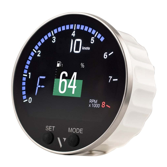
DESCRIPTION DESCRIPTION DISPLAY SEGMENTS Part Description Area to show data pages and menu Gear position Current speed according to the selected unit of measurement Engine speed Alarm telltales SET / Buttons to interact with the data pages and MODE the menu DATA PAGES Single layout Dual layout... -
Page 17: Basic Actions
You can choose which pages to hide/show in the menu under Display > Screens. If you are working with the Veratron Diagnostic Tool, you can make the selection of shown and hidden screens faster by making this setting in the Configuration Tool. -
Page 18: Distance Traveled
DESCRIPTION Input signal Output Icon Information Unit NMEA NMEA Internal Frequency Resistive 0-5V EasyLink 2000 2000 Battery Status of health Battery temperature °C / °F Engine coolant °C / °F temperature Engine coolant bar / psi pressure Engine oil °C / °F temperature Engine oil pressure bar / psi... -
Page 19: Engine Hours
DESCRIPTION ENGINE HOURS In the absence of data received from the NMEA 2000 network, the indicator considers the internally calculated data. Time is count when the engine speed exceeds 300 RPM. In the presence of data from the NMEA 2000 network, the indicator considers the data received from the network only if higher than the internal data. -
Page 20: General Settings
GENERAL SETTINGS GENERAL SETTINGS SETTINGS MENU STRUCTURE OPERATE THE SETTINGS MENU To... Then... Press the SET button until the first menu item appears. enter the settings menu • To go to the previous item/value, briefly press the MODE scroll through the settings menu items and possible values button. -
Page 21: Units Menu Structure
GENERAL SETTINGS UNITS MENU STRUCTURE Possible Setting Description values/commands* Speed Speed units km/h , mph, kts Trip Unit of measurement of distance travelled km , mile , nm Flow Flow measurement units L/h , gph Tank Unit of measurement for the liquid in the tank L , US gal Temperatures Temperature units... -
Page 22: Set The Day/Night Mode
GENERAL SETTINGS SET THE DAY/NIGHT MODE To set the desired mode, act on pin 10 of the MX150 connector as follows: To set the mode... Then... move the pin switch to GND/OPEN. night move the pin switch to BATTERY PLUS. CHANGE THE BRIGHTNESS OF THE DISPLAY The change affects the set day or night mode. -
Page 23: Engine Identification
A custom splash logo can be loaded from a PC using the Veratron Configuration Tool. This logo will then be displayed each time during the startup sequence of the device. For more information, please refer to the Veratron Configuration Tool user manual or contact your Veratron reseller. -
Page 24: Sensor Configuration
TYPES OF CALIBRATION Calibration of analog sensors can be: • Standard: only for Veratron sensors. You define the type of sensor, and the device reads with good approximation the value of the sensor without the need of calibration. • Manual: For non-Veratron sensors or to obtain a more accurate indication from a Veratron sensor. A three- or five-point procedure instructs the system to detect the sensor value. -
Page 25: Calibrate The Sensors
SENSOR CONFIGURATION CALIBRATE THE SENSORS FUEL LEVEL SENSOR • Connect the sensor of interest. See “Connecting an analogue sensor”. • Under Sensors select the resistive or voltage depending input to which the sensor is connected. • Under Fuel > Sensor, choose the desired configuration. •... - Page 26 • Choose the desired configuration for the connected sensor type. • If you chose the CUSTOM configuration, create the sensor curve using the Veratron Configuration Tool. INTELLIGENT BATTERY SENSOR (IBS) • Connect the sensor of interest. See “Connecting the Intelligence Battery Sensor”.
-
Page 27: Sensor Curves
Here are the possible alternatives: Selectable value Curve Single 10-180 Ω Dual 5-90 Ω CUSTOM Three-step calibration wizard COOLANT TEMPERATURE SENSORS Here are the possible alternatives: Selectable value Curve 120° 291-22 Ω 120° * 0-5V Linear CUSTOM Calibration via Veratron Configuration Tool B001167... - Page 28 Here are the possible alternatives: Selectable value Curve 150° 197-11 Ω 150° * 0-5V Linear CUSTOM Calibration via Veratron Configuration Tool OIL PRESSURE SENSORS Here are the possible alternatives: Selectable value Curve 5 bar 10-184 Ω 5 bar * 0-5V Linear 10 bar 10-184 Ω...
-
Page 29: Alarms
ALARMS ALARMS ALARMS NOTIFICATION The VMH 35 indicator shows internal active alarms and those coming from NMEA 2000. The ALARMS item allows you to set the alarms that can be generated by the indicator and the relative alarm thresholds. In the event of an alarm, the following appears on the display: •... -
Page 30: Set An Alarm
ALARMS SET AN ALARM • In ALARMS > Setup select the value to activate the alarm and then Active. • Set the desired alarm threshold. LIST OF MANAGED ALARMS Local alarms NMEA 2000 • • Engine Overtemp Water in fuel •... -
Page 31: Troubleshooting
TROUBLESHOOTING TROUBLESHOOTING DATA DISPLAY Problem Root cause Solution The values Incorrect sensor configuration. Check the configuration in the Sensors menu. displayed are not Sensor connected incorrectly. Check the connection, refer to the Installation as expected. Instructions. The NMEA 2000 network Check the connections and that there is a backbone has not been termination at both the beginning and end of the... -
Page 32: Technical Data
TECHNICAL DATA TECHNICAL DATA GENERAL FEATURES Material Mineral glass front lens Stainless steel frame • Connectors Molex MX150 (with EasyLink connector integrated in the pigtail cable) • NMEA 2000 Micro-C M12 5 Pin • Input data 2 analogue resistive inputs (0-400 Ω) •... -
Page 33: Compliance
TECHNICAL DATA COMPLIANCE Compliance UKCA UL94 Directives 2014/30/EU (Electromagnetic compatibility) 2011/65/EU (Hazardous substances in electrical and electronic equipment) Reference standards IEC 60945: 2002-08 (environmental class: exposed) SUPPORTED NMEA 2000 MESSAGES Description Description Navigation data 129284 Engine Parameters, Rapid Update 127488 GNSS dilution of precision (DOP) 129539 Engine Parameters, Dynamic... -
Page 34: Spare Parts And Accessories
Pigtail cable with MX150 connector A2C14333300 Spin lock A2C13760900 EasyLink extension cable A2C59500139 Rubber gasket A2C14624100 Wiring harness for outboard engines B00106601 IBS (Intelligent Battery Sensor) 12V Gen. I B00043901 Adapter cable for IBS B00090601 For all available accessories, visit http://www.veratron.com. B001167... - Page 35 - Print the document in its original format, in whole or in part. - Copy of contents without modification and declaration of Veratron AG as copyright owner. Veratron AG reserves the right to make changes or improvements to this documentation without notice. Requests for permission, additional copies of this manual, or technical information about this manual should be directed to Veratron AG.
- Page 36 VMH 35 MARINE DISPLAY BEDIENUNGSANLEITUNG rev. AD B001167...
- Page 37 INHALT INHALT EINFÜHRUNG ............3 ALLGEMEINE EINSTELLUNGEN ..... 19 Architektur ................. 3 Menustruktur ..............19 VMH 35-Varianten ............3 Bedienung des Einstellungsmenüs ...... 19 Units Menüstruktur ............. 20 SICHERHEITSHINWEISE ........4 Einstellen des Tag-/Nachtmodus ......21 Während des Einbaus beachten ......4 Ändern der Display-Helligkeit .........
-
Page 38: Einführung
EINFÜHRUNG EINFÜHRUNG VMH 35 ist ein NMEA 2000-zertifiziertes Gerät, das für die Überwachung von Aussenbordmotoren entwickelt wurde. Ausgestattet mit analogen Eingängen eignet es sich auch für die Nachrüstung älterer Motoren und ermöglicht den direkten Anschluss verschiedener Sensoren wie Kraftstoff, Trimmung und Drehzahlmesser, während das eingebaute NMEA-2000-Gateway diese Messungen an andere digitale Netzwerkgeräte wie Kartenplotter weiterleitet und so einen externen Konverter überflüssig macht. -
Page 39: Sicherheitshinweise
SICHERHEITSHINWEISE SICHERHEITSHINWEISE WARNUNG • Nicht rauchen! Kein offenes Feuer oder Wärmequellen! • Das Produkt wurde unter Beachtung der • Beachten Sie eventuelle Veränderungen am grundlegenden Sicherheitsanforderungen der Fahrzeug, die beim Einbau zu berücksichtigen EG-Richtlinien und dem anerkannten Stand sind! • Für den Einbau sind Grundkenntnisse der der Technik entwickelt, gefertigt und geprüft. -
Page 40: Nach Dem Einbau Beachten
SICHERHEITSHINWEISE • Bei notwendigen Arbeiten ohne flüchtigen elektronischen Speicher ihre eingegebenen Werte verlieren und neu Spannungsunterbrechung darf nur mit programmiert werden müssen. isoliertem Werkzeug gearbeitet werden. • Lassen Sie bei Bootsmotoren vor Beginn der • Benutzen Sie zum Messen von Spannungen Arbeiten im Motorraum bei Benzinmotoren und Strömen im Fahrzeug/ Maschine bzw. - Page 41 SICHERHEITSHINWEISE die Sicherheitshinweise der Handwerkzeughersteller. • Isolieren Sie freigelegte Litzen so, dass keine Kurzschlüsse entstehen können. • Achtung: Kurzschlussgefahr durch fehlerhafte Verbindungsstellen oder beschädigte Kabel. • Kurzschlüsse im Bordnetz können Kabelbrände, Batterieexplosionen und Beschädigungen anderer elektronischer Systeme verursachen. Deshalb müssen alle Verbindungen der Spannungsversorgung mit verschweissbaren Stossverbindern versehen und ausreichend isoliert sein.
-
Page 42: Vmh 35 Installation
VMH 35 INSTALLATION VMH 35 INSTALLATION WARNUNG Vor Beginn der Arbeiten ist der Minuspol der Batterie abzuklemmen, da sonst Kurzschlussgefahr besteht. Wenn das Fahrzeug über Zusatzbatterien verfügt, müssen ggf. auch die Minuspole dieser Batterien abgeklemmt werden! Kurzschlüsse können Kabelbrände, Batterieexplosionen und Beschädigungen von anderen elektronischen Systemen verursachen. -
Page 43: Spinlock-Montage
VMH 35 INSTALLATION SPINLOCK-MONTAGE Die Paneldicke kann in einem Bereich von 2 bis 20 mm liegen. Das Bohrloch muss einen Durchmesser von 86 mm haben. WARNUNG • Bohren Sie keine Löcher oder Montageöffnungen in Stütz- oder Stabilisierungsbalken! • Der Montageort muss einen ausreichenden Freiraum hinter den Befestigungslöchern oder - öffnungen aufweisen. -
Page 44: Outboard-Engine-Kit Installation
OUTBOARD-ENGINE-KIT INSTALLATION OUTBOARD-ENGINE-KIT INSTALLATION WARNUNG Bevor Sie beginnen, klemmen Sie den Minuspol der Batterie ab, sonst riskieren Sie einen Kurzschluss. Wenn das Fahrzeug von Zusatzbatterien versorgt wird, müssen Sie auch die Minuspole dieser Batterien abklemmen! Kurzschlüsse können Brände, Batterieexplosionen und Schäden an anderen elektronischen Systemen verursachen. -
Page 45: Einbau Des Outboard-Engine-Kits
Schliessen Sie den widerstandsabhängigen Ausgang an den Füllstandsensor an. Der am Kabelbaum installierte Stecker passt zu den Kraftstofffüllstandssensoren von Veratron. Falls Ihr Sensor nicht dazu passt, schneiden Sie den Stecker ab und krimpen Sie die passende Verbindung an die Kabelenden. -
Page 46: Ibs-Systemanforderungen
OUTBOARD-ENGINE-KIT INSTALLATION Montieren Sie das VMH 35 Bauen Sie das VMH 35 in das Loch im Armaturenbrett ein. Weitere Informationen zu den Installationsanforderungen finden Sie im Abschnitt "VMH 35 Installation". EasyLink-Satelliten Wenn Sie zusätzliche VMH 14 Satellitengeräte haben, installieren Sie diese ebenfalls auf dem Armaturenbrett und schliessen Sie sie an den EasyLink-Anschluss an. -
Page 47: Elektrische Anschlüsse
ELEKTRISCHE ANSCHLÜSSE ELEKTRISCHE ANSCHLÜSSE WARNUNG • Beachten Sie die Anweisungen, die im Abschnitt "Elektrische Anschlüsse" des Kapitels "Sicherheitshinweise" in diesem Dokument beschrieben sind! PINBELEGUNG Beschreibung Pin Nr. Kabelfarbe VMH 35 VMH 35-S KL. 30 - Batterie Plus 12 V Schwarz KL. -
Page 48: Elektrischer Schaltplan
Der Ein/Aus-Modus hängt vom Zündsignal an Klemme 15 (Molex-Stecker Pin 7) ab. High-Pegel um das Gerät einzuschalten, gegen Masse oder offene Verbindung, um es auszuschalten. Beim Einschalten leuchten die Drehzahlanzeige und die Warnleuchten kurz auf, das Veratron-Logo erscheint und dann wird die letzte Datenseite vor dem Ausschalten angezeigt. -
Page 49: Analoge Sensoren (Res, 0-5V, Rpm)
ELEKTRISCHE ANSCHLÜSSE ANALOGE SENSOREN (RES, 0-5V, RPM) Jeder Sensor, der an einen Analogeingang (RES 1, RES 2, 0-5V, RPM) des Displays angeschlossen ist, muss wie im Schaltplan dargestellt verbunden werden. Es ist ratsam, Sensoren mit isolierter Masse zu verwenden, und es muss sichergestellt werden, dass die Sensormasse mit der Masse des Displays verbunden ist, um falsche Messwerte zu vermeiden. -
Page 50: Beschreibung
BESCHREIBUNG BESCHREIBUNG BILDSCHIRMELEMENTE Teil Beschreibung Bereich zur Anzeige von Datenseiten und Menü Gang Fahrgeschwindigkeit in der gewählten Masseinheit Motordrehzahl Alarm-Kontrollleuchten SET / Schaltflächen zur Interaktion mit den MODE Datenseiten und dem Menü DATENSEITEN Single Layout Dual Layout A: Daten-Symbol Zeigt an, welcher Datentyp gerade angezeigt wird. Bei gewissen Datentypen wird hier auch noch die Instanz angezeigt. -
Page 51: Grundlegende Bedienung
Sie können im Menü unter Display > Bildschirme auswählen, welche Seiten ein- und ausgeblendet werden sollen. Wenn Sie mit dem Veratron Diagnostic Tool arbeiten, können Sie die Auswahl der angezeigten und ausgeblendeten Bildschirme beschleunigen, indem Sie diese Einstellung im Configuration Tool vornehmen. -
Page 52: Zurückgelegte Entfernung
BESCHREIBUNG Eingangssignal Ausgabe Symbol Informationen Einheit NMEA NMEA Intern Frequenz Resistiv 0-5V EasyLink 2000 2000 Autonomie der d / h Batterie Batterie Gesundheitszustand Batterietemperatur °C / °F Temperatur des °C / °F Motorkühlmittels Kühlmitteldruck im bar / psi Motor Motoröltemperatur °C / °F Motoröldruck bar / psi... -
Page 53: Motorbetriebsstunden
BESCHREIBUNG MOTORBETRIEBSSTUNDEN Wenn keine Daten aus dem NMEA 2000-Netzwerk empfangen werden, berücksichtigt die Anzeige die intern berechneten Daten. Die Zeit wird gezählt, wenn die Motordrehzahl 300 RPM überschreitet. Bei Vorhandensein von Daten aus dem NMEA-2000-Netz berücksichtigt das VMH die vom Netz empfangenen Daten nur, wenn sie höher sind als die internen Daten. -
Page 54: Allgemeine Einstellungen
ALLGEMEINE EINSTELLUNGEN ALLGEMEINE EINSTELLUNGEN MENUSTRUKTUR BEDIENUNG DES EINSTELLUNGSMENÜS Um … , soll … SET gedrückt gehalten werden. das Einstellungsmenü aufzurufen • kurz Mode gedrückt werden, für den vorherigen Wert. durch die Menüpunkte der Einstellungen und die möglichen Werte • kurz SET gedrückt werden, für den folgenden Wert. zu blättern zu bestätigen. -
Page 55: Units Menüstruktur
ALLGEMEINE EINSTELLUNGEN UNITS MENÜSTRUKTUR Einstellung Beschreibung Auswahl * Speed Geschwindigkeitseinheiten km/h , mph, kts Trip Masseinheit für die zurückgelegte Entfernungen km , Meile , nm Flow Einheiten zur Durchflussmessung L/h , gph Tank Masseinheit für die Flüssigkeitsmengen L , US gal Temperatures Temperatur-Einheiten °C , °F... -
Page 56: Einstellen Des Tag-/Nachtmodus
ALLGEMEINE EINSTELLUNGEN EINSTELLEN DES TAG-/NACHTMODUS Um den gewünschten Modus einzustellen, wirken Sie wie folgt auf Pin 10 des MX150-Steckers ein: Um den …-Modus einzustellen, Pin 10 gegen Masse/Offen schalten. Nacht gegen die Batterie Plus (+12V) schalten. ÄNDERN DER DISPLAY-HELLIGKEIT Die Änderung betrifft den aktuell eingestellten Tag- oder Nachtmodus. •... -
Page 57: Motor-Benennung
Ein benutzerdefiniertes Splash-Logo kann mit dem Veratron Configuration Tool von einem PC geladen werden. Dieses wird dann jedes Mal während dem Aufstarten des Geräts kurz angezeigt. Weitere Informationen finden Sie in der Bedienungsanleitung für das Veratron Configuration Tool oder bei Ihrem Veratron-Händler. -
Page 58: Sensor-Konfiguration
ARTEN DER KALIBRIERUNG Ein Sensor kann auf folgende Arten kalibriert werden: • Standard: nur für Veratron-Sensoren. Sie definieren den Sensortyp, und das Gerät liest mit guter Annäherung den Wert des Sensors, ohne dass eine Kalibrierung erforderlich ist. • Manuell: Für Nicht-Veratron-Sensoren oder um eine genauere Anzeige von einem Veratron-Sensor zu erhalten. -
Page 59: Sensoren Kalibrieren
SENSOR-KONFIGURATION SENSOREN KALIBRIEREN KRAFTSTOFFFÜLLSTANDSSENSOR • Schliessen Sie den gewünschten Sensor an. Siehe "Anschliessen eines analogen Sensors". • Wählen Sie unter SENSORS den widerstandsabhängigen oder spannungsabhängigen Eingang, an den der Sensor angeschlossen ist. • Wählen Sie unter Kraftstoff > Sensor die gewünschte Konfiguration. •... - Page 60 Sensor angeschlossen ist. • Wählen Sie die gewünschte Konfiguration für den angeschlossenen Sensortyp. • Wenn Sie die Konfiguration CUSTOM gewählt haben, erstellen Sie die Sensorkurve mit dem veratron Configuration Tool. INTELLIGENTER BATTERIESENSOR (IBS) • Schliessen Sie den gewünschten Sensor an. Siehe "Anschliessen des Intelligenzbatteriesensors".
-
Page 61: Sensorkurven
Fünfstufiger Kalibrierungsassistent RUDERLAGENSENSOREN Diese Standardkurven stehen zur Auswahl: Optionen Kurve Einzeln 10-180 Ω Dual 5-90 Ω CUSTOM Dreistufiger Kalibrierungsassistent KÜHLMITTELTEMPERATURSENSOREN Diese Standardkurven stehen zur Auswahl: Optionen Kurve 120° 291-22 Ω 120° * 0-5V Linear CUSTOM Kalibrierung über Veratron Configuration Tool B001167... - Page 62 ÖLTEMPERATURSENSOREN Diese Standardkurven stehen zur Auswahl: Optionen Kurve 150° 197-11 Ω 150° * 0-5V Linear CUSTOM Kalibrierung über Veratron Configuration Tool ÖLDRUCKSENSOREN Diese Standardkurven stehen zur Auswahl: Optionen Kurve 5 bar 10-184 Ω 5 bar * 0-5V Linear 10 bar 10-184 Ω...
-
Page 63: Alarme
ALARME ALARME ALARMANZEIGEN Das VMH 35-Display zeigt interne aktive Alarme und Alarme aus dem NMEA 2000 Netzwerk. Unter ALARMS können Sie die Alarme und ihre Schwellwerte einstellen. Im Falle eines Alarms wird auf dem Display Folgendes angezeigt: • Das Alarm-Popup erscheint. •... -
Page 64: Einen Alarm Einstellen
ALARME EINEN ALARM EINSTELLEN • Wählen Sie unter ALARME > Setup den Wert, der den Alarm aktivieren soll, und dann Active. • Stellen Sie den gewünschten Schwellwert für den Alarm ein. LISTE DER VERWALTETEN ALARME Lokale Alarme NMEA 2000 • •... -
Page 65: Fehlersuche
FEHLERSUCHE FEHLERSUCHE DATENANZEIGE Problem Grundlegende Ursache Lösung Die angezeigten Falsche Sensorkonfiguration. Überprüfen Sie die Konfiguration im Menü Werte sind nicht Sensoren. wie erwartet. Sensor falsch angeschlossen. Überprüfen Sie den Anschluss, siehe Installationsanleitung. Der NMEA 2000 Netzwerk- Überprüfen Sie die Anschlüsse und dass sowohl am Backbone ist nicht korrekt Anfang als auch am Ende des Backbones ein erstellt worden. -
Page 66: Technische Daten
TECHNISCHE DATEN TECHNISCHE DATEN ALLGEMEIN Material Frontlinse aus Mineralglas Rahmen aus rostfreiem Stahl • Steckverbinder Molex MX150 (mit integrierter EasyLink-Schnittstelle) • NMEA 2000 Mikro-C M12 5 Pin • Daten-Eingänge 2 analoge widerstandsabhängige Eingänge (0-400Ω) • 1 Frequenzeingang (0-4 kHz) • 1 LIN-Bus •... -
Page 67: Konformität
TECHNISCHE DATEN KONFORMITÄT Einhaltung der Vorschriften UKCA UL94 Richtlinien 2014/30/EU (Elektromagnetische Verträglichkeit) 2011/65/EU (Gefährliche Stoffe in Elektro- und Elektronikgeräten) Referenznormen IEC 60945: 2002-08 (Umweltklasse: ausgesetzt) UNTERSTÜTZTE NMEA 2000-PGNS Beschreibung Beschreibung Navigation data 129284 Engine Parameters, Rapid Update 127488 GNSS dilution of precision (DOP) 129539 Engine Parameters, Dynamic 127489... -
Page 68: Ersatzteile Und Zubehör
ERSATZTEILE UND ZUBEHÖR ERSATZTEILE UND ZUBEHÖR Produkt Teilenummer Pigtailkabel mit MX150-Stecker A2C14333300 Drehverschluss A2C13760900 EasyLink-Verlängerungskabel A2C59500139 Gummidichtung A2C14624100 Kabelbaum für Aussenbordmotoren B00106601 IBS (Intelligenter Batteriesensor) 12V Gen. I B00043901 Adapterkabel für IBS B00090601 Alle verfügbaren Zubehörteile finden Sie unter http://www.veratron.com. B001167... - Page 69 - Drucken Sie das Dokument ganz oder teilweise in seinem ursprünglichen Format. - Unveränderte Übernahme der Inhalte und Erklärung der Veratron AG als Urheberrechtsinhaberin. Veratron AG behält sich das Recht vor, Änderungen oder Verbesserungen an dieser Dokumentation ohne vorherige Ankündigung vorzunehmen. Anfragen für Genehmigungen, zusätzliche Kopien dieses Handbuchs oder technische Informationen zu diesem Handbuch sollten an die Veratron AG gerichtet werden.
- Page 70 VMH 35 MARINE DISPLAY MANUALE UTENTE rev. AD B001167...
-
Page 71: Indice
INDICE INDICE INDICE ............... 2 Menu setup............... 21 Identificativo del motore ..........21 INTRODUZIONE ............. 3 Azzerare un contatore ..........22 Schema di funzionamento .......... 3 Caricare uno startup logo personalizzato ..22 VMH 35 varianti ............... 3 CONFIGURAZIONE DEI SENSORI ....23 INFORMAZIONI SULLA SICUREZZA....4 Tipi di calibrazione ............ -
Page 72: Introduzione
INTRODUZIONE INTRODUZIONE Il display VMH 35 è un dispositivo certificato NMEA 2000 progettato per il monitoraggio dei motori fuoribordo. Dotato di ingressi analogici è anche adatto per il refitting di vecchi motori permettendo il collegamento diretto di vari sensori come carburante, trim e contagiri, mentre il gateway NMEA 2000 integrato distribuisce queste misure ad altri dispositivi di rete digitali come i chartplotters, risparmiando la necessità... -
Page 73: Informazioni Sulla Sicurezza
L'uso del prodotto per motivi diversi da quelli • Modifiche o manipolazioni ai prodotti previsti può portare a lesioni personali, danni Veratron possono influire sulla sicurezza. Di alla proprietà o all'ambiente. Prima conseguenza, non potete modificare o dell'installazione, controllare la... -
Page 74: Sicurezza Dopo L'installazione
INFORMAZIONI SULLA SICUREZZA valori di ingresso e devono essere Seguire le istruzioni di sicurezza del riprogrammate. produttore dell'utensile. • Se si lavora su motori di barche a benzina, • Usare solo strumenti isolati, se è necessario lasciar girare la ventola del vano motore prima lavorare su parti sotto tensione. - Page 75 INFORMAZIONI SULLA SICUREZZA alimentazione devono essere dotati di • Se lo strumento funziona su alimentatori, si connettori saldabili ed essere noti che l'alimentatore deve essere sufficientemente isolati. stabilizzato e deve essere conforme alla • Assicurarsi che i collegamenti a terra siano seguente norma: DIN EN 61000, parti da 6-1 a 6-4 sani.
-
Page 76: Installazione Del Display Vmh 35
INSTALLAZIONE DEL DISPLAY VMH 35 INSTALLAZIONE DEL DISPLAY VMH 35 ATTENZIONE Prima di iniziare il lavoro, scollegare il terminale negativo della batteria per evitare il rischio di un corto circuito. Se il veicolo è dotato di batterie supplementari, è necessario scollegare anche il terminale negativo di tutte le batterie, se necessario. -
Page 77: Montaggio Con Spinlock
INSTALLAZIONE DEL DISPLAY VMH 35 MONTAGGIO CON SPINLOCK Lo spessore del pannello può essere compreso tra 2 e 20 mm. Il foro deve avere un diametro di 86 mm. ATTENZIONE • Non praticare fori o aperture di installazione nelle travi di sostegno o di stabilizzazione! •... -
Page 78: Installazione Outboard Engine Kit
INSTALLAZIONE DEL OUTBOARD ENGINE KIT INSTALLAZIONE OUTBOARD ENGINE KIT ATTENZIONE Prima di iniziare, scollegate il terminale negativo della batteria, per evitare corto circuiti. Se il sistema è alimentato da batterie ausiliarie, è necessario scollegare anche i terminali negativi di queste batterie! I cortocircuiti possono causare incendi, esplosioni della batteria e danni ad altri sistemi elettronici. -
Page 79: Installazione
Collegare l’ingresso resistivo RES2 al sensore del livello del carburante. Il connettore presente sul cablaggio corrisponde ai sensori di livello del carburante Veratron. Nel caso in cui il vostro sensore non si adatti, rimuovere il connettore e collegare le estremità dei fili manualmente. -
Page 80: Requisiti Di Sistema Di Ibs
COLLEGAMENTI ELETTRICI Montare il display VMH 35 Installare il VMH 35 come descritto nella sezione "Installazione del display VMH 35". Installazione strumenti satellite EasyLink (opz.) Nel caso siano da installare degli indicatori satellite VMH 14, procedere con l’installazione a pannello ed al collegamento tramite il connettore EasyLink presente sul cablaggio. -
Page 81: Collegamenti Elettrici
COLLEGAMENTI ELETTRICI COLLEGAMENTI ELETTRICI ATTENZIONE • Fare riferimento alle regole di sicurezza descritte nella sezione dei collegamenti elettrici del capitolo sulle informazioni di sicurezza di questo documento! PINOUT Descrizione Pin No. Colore VMH 35 VMH 35-S / ... w/o GPS Rosso Alimentazione permanente 12 V (Term.30) Nero... -
Page 82: Schema Elettrico
Molex). Commutare il terminale al positivo per accendere il display, e a massa o circuito aperto per spegnerlo. All'accensione, il contagiri e le spie si accendono brevemente, appare il logo Veratron e poi viene visualizzata l'ultima schermata dati mostrata prima dello spegnimento. -
Page 83: Sensori Analogici (Res, 0-5V, Rpm)
COLLEGAMENTI ELETTRICI SENSORI ANALOGICI (RES, 0-5V, RPM) Qualsiasi sensore collegato a un ingresso analogico (RES 1, RES 2, 0-5V, RPM) del display deve essere collegato come mostrato in figura. Si consiglia di utilizzare sensori con massa isolata, ed è necessario assicurarsi che la massa del sensore sia collegata alla massa del display per evitare letture errate. -
Page 84: Descrizione
DESCRIZIONE DESCRIZIONE Parte Descrizione Display TFT per pagine dati e menu Posizione dell’invertitore di marcia Velocità attuale secondo l'unità di misura selezionata Contagiri Allarmi SET / Pulsanti per interagire con le MODO pagine dati e il menu SCHERMI DATI Single layout Dual layout A: Simbolo del dato visualizzato Indica quale tipo di dato viene visualizzato in questo momento. -
Page 85: Selezionare Le Pagine Da Visualizzare
DESCRIZIONE AZIONI DI BASE Per... Quindi... aprire il menu Tenere premuto SET scorrere le pagine Per tornare alla pagina precedente, premere brevemente il pulsante MODE. Per passare alla pagina successiva, premere brevemente il pulsante SET. regolare la retroilluminazione Premere brevemente i pulsanti SET e MODE contemporaneamente smorzare il pop-up dell'allarme Premere qualsiasi pulsante... - Page 86 DESCRIZIONE Segnale d'ingresso Uscita Icona/Testo Dato Unità NMEA NMEA Interno Frequenza Resistivo EasyLink 2000 2000 Livello acque % / L / Gal FRESH chiare Livello acque % / L / Gal WASTE scure Voltmetro Amperometro Stato di carica della batteria Autonomia della d / h batteria...
-
Page 87: Contaore Motore
DESCRIZIONE CONTAORE MOTORE In assenza di dati ricevuti dalla rete NMEA 2000, l'indicatore considera i dati calcolati internamente. Il tempo viene conteggiato quando la velocità del motore supera i 300 giri/min. In presenza di dati provenienti dalla rete NMEA 2000, l'indicatore considera il dato ricevuto dalla rete solo se superiore al contatore interno. -
Page 88: Impostazioni Generali
IMPOSTAZIONI GENERALI IMPOSTAZIONI GENERALI STRUTTURA DEL MENU IMPOSTAZIONI UTILIZZARE IL MENU IMPOSTAZIONI Per... Quindi... entrare nel menu delle impostazioni Premere il pulsante SET finché non appare la prima voce del menu. • scorrere le voci del menu e i possibili Per andare alla voce/valore precedente, premere valori brevemente il pulsante MODE. -
Page 89: Menu Unità
IMPOSTAZIONI GENERALI MENU UNITÀ Impostazione Descrizione Valori/comandi possibili* Speed Unità di velocità kmh/ mph/ kts TRIP Unità di misura della distanza percorsa km / mile / nm Flow Unità di misura del flusso carburante lh / gph Tank Unità di misura del livello l / US gal Temperatures Unità... -
Page 90: Cambiare La Luminosità Del Display
IMPOSTAZIONI GENERALI CAMBIARE LA LUMINOSITÀ DEL DISPLAY Questa voce del menu riguarda la modalità giorno o notte del display. • Premere il pulsante MODE finché non appare il menu DISPLAY con Backlight evidenziato. • Premere il pulsante SET per confermare la voce di menu. •... -
Page 91: Azzerare Un Contatore
Tenere premuto il pulsante SET finché il valore non si azzera. CARICARE UNO STARTUP LOGO PERSONALIZZATO Un logo personalizzato, visualizzato all’accensione del display, può essere caricato da PC usando il Veratron Configuration Tool. Per ulteriori informazioni, fare riferimento al manuale utente del Configuration Tool Veratron o contattare il proprio rivenditore Veratron. -
Page 92: Configurazione Dei Sensori
TIPI DI CALIBRAZIONE La calibrazione dei sensori analogici può essere: • Standard: solo per i sensori Veratron. Si definisce il tipo di sensore e il dispositivo legge con buona approssimazione il valore del sensore senza bisogno di calibrazione. • Manuale: Per sensori non Veratron o per ottenere un'indicazione più precisa da un sensore Veratron. -
Page 93: Calibrare I Sensori
CONFIGURAZIONE DEI SENSORI CALIBRARE I SENSORI Sensore di livello del carburante • Collegare il sensore di interesse. Vedere Collegamento di un sensore analogico. • Sotto Sensors selezionate l'ingresso resistivo a cui è collegato il sensore. • Sotto Fuel > Sensor, scegliete il tipo di configurazione desiderato. •... -
Page 94: Sensori Di Temperatura E Pressione
Sotto Sensors selezionate l'ingresso resistivo a cui è collegato il sensore. • Scegliere il tipo di configurazione desiderato per il tipo si sensore collegato. • Nel caso si sia scelta la configurazione CUSTOM, creare la curva del sensore usando il Veratron Configuration Tool. SENSORE DI BATTERIA INTELLIGENTE (IBS) •... -
Page 95: Curve Dei Sensori
5-90 Ω Doppia stazione CUSTOM Procedura guidata di calibrazione in tre step SENSORI DI TEMPERATURA DEL REFRIGERANTE Di seguito le possibili alternative: Valore selezionabile Caratteristica 291-22 Ω 120° 120° * 0 – 5V CUSTOM Calibrazione tramite Veratron Configuration Tool B001167... -
Page 96: Sensori Di Temperatura Dell'olio
Di seguito le possibili alternative: Valore selezionabile Caratteristica 197-11 Ω 150° 150° * 0-5V Linear CUSTOM Calibrazione tramite Veratron Configuration Tool SENSORI DI PRESSIONE DELL'OLIO Di seguito le possibili alternative: Valore selezionabile Caratteristica 10-184 Ω 5 bar 0-5V Linear 5 bar * 0-5V Linear 10-184 Ω... -
Page 97: Allarmi
ALLARMI ALLARMI NOTIFICA DEGLI ALLARMI Il display VMH 35 indica gli allarmi attivi locali (configurati da menu) e quelli provenienti dala rete NMEA 2000. Il menu ALARMS permette di impostare gli allarmi che possono essere generati localmente e le relative soglie di allarme. -
Page 98: Elenco Degli Allarmi Gestiti
ALLARMI ELENCO DEGLI ALLARMI GESTITI Allarmi locali NMEA 2000 • • Sovratemperatura del motore Acqua nel carburante • • Batteria scarica Sovratemperatura del motore • • Sovratensione Batteria scarica • • Bassa carica della batteria Bassa pressione dell'olio • • Sovratemperatura della batteria Controllare il motore •... -
Page 99: Risoluzione Dei Problemi
RISOLUZIONE DEI PROBLEMI RISOLUZIONE DEI PROBLEMI VISUALIZZAZIONE DEI DATI Problema Causa principale Soluzione I valori visualizzati Configurazione errata del Controllare la configurazione nel menu Sensors. non sono quelli sensore. previsti. Sensore collegato in modo Controllare il collegamento, fare riferimento alle errato. -
Page 100: Dati Tecnici
DATI TECNICI DATI TECNICI CARATTERISTICHE GENERALI Materiale Lente frontale in vetro minerale Cornice in acciaio inossidabile • Connettori Molex MX150 (con connettore EasyLink integrato nel cablaggio) • NMEA 2000 Micro-C M12 5 pin Ingressi analogici • 2x ingressi resistivi (0-400 Ω) •... -
Page 101: Compliance
DATI TECNICI COMPLIANCE Conformità UKCA UL94 Direttive 2014/30/UE (compatibilità elettromagnetica) 2011/65/UE (sostanze pericolose nelle apparecchiature elettriche ed elettroniche) Norme di riferimento IEC 60945: 2002-08 (classe ambientale: Exposed device) MESSAGGI NMEA 2000 SUPPORTATI Descrizione Descrizione Navigation data 129284 Engine Parameters, Rapid Update 127488 GNSS dilution of precision (DOP) 129539... -
Page 102: Ricambi Ed Accessori
Cavo di estensione EasyLink A2C59500139 Guarnizione in gomma A2C14624100 ACCESSORI Prodotto Codice Cablaggio per motori fuoribordo B00106601 IBS (sensore batteria intelligente) 12V Gen. I B00043901 Cavo adattatore per IBS B00090601 Per tutti gli accessori disponibili, visitare il sito www.veratron.com B001167... - Page 103 - Copia dei contenuti senza modifiche e dichiarazione di Veratron AG come proprietario del copyright. Veratron AG si riserva il diritto di apportare modifiche o miglioramenti a questa documentazione senza preavviso. Richieste di autorizzazione, copie aggiuntive di questo manuale o informazioni tecniche su questo manuale devono essere indirizzate a veratron AG.
Need help?
Do you have a question about the VMH Series and is the answer not in the manual?
Questions and answers