Advertisement
Quick Links
IMPORTANT
Carefully remove all the parts from the carton and
place them individually on a soft cloth to prevent
scratches or other damage.
Carefully and strictly follow these assembly instructions
to ensure a completed product as designed.
Do not use power tools above 8 volts to assemble.
Part List
A.
Top
1 pc.
E.
Rail
1 pc.
F.
Rail
1 pc.
G.
Back Rail
1 pc.
H.
Back Rail
1 pc.
K.
Base
1 pc.
Tool(s) required for assembly: Phillips screwdriver
home
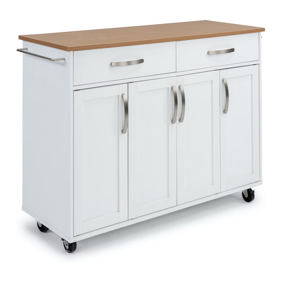
4410-95
Kitchen Cart
styles Customer Service: www.homestylesfurniture.com,
servicedesk@homestylesfurniture.com,
B.
Side Panel
1 pc.
I.
Divider
1 pc.
L.
Shelf
4 pcs.
N.
O.
Door
Door
2 pcs.
2 pcs.
888-680-7460
C.
Side Panel
1 pc.
M.
Shelf
2 pcs.
P.
Drawer
1 pc.
Q.
Drawer
1 pc.
Refer to later page(s) of these
instructions for drawer assembly.
D.
Middle Panel
2 pcs.
J.
Back Panel
1 pc.
Advertisement

Related Manuals for Homestyles 4410-95


Summary of Contents for Homestyles 4410-95
- Page 1 4410-95 Kitchen Cart IMPORTANT Carefully remove all the parts from the carton and place them individually on a soft cloth to prevent scratches or other damage. Carefully and strictly follow these assembly instructions to ensure a completed product as designed.
-
Page 2: Hardware List
Assembly Instructions 2/11 Hardware List M7x10 M3.5x12 Cam Lock Screw Cam Lock Varianta Screw Magnet Screw Magnet 29 pcs. (+4 extra) 29 pcs. (+4 extra) 8 pcs. (+1 extra) 8 pcs. (+1 extra) 4 pcs. M7x50 M x16 M6x25 Dowel Cover Assembly Screw... - Page 3 Assembly Instructions 3/11 IMPORTANT Ÿ Use a soft cloth between these parts and the floor. Ÿ Do not use power tools above 8 volts to assemble. Left Guide Varianta Screw Cam Lock Screw Magnet Screw Magnet Right Guide STEP 1 Insert Cam Lock Screws into pre-drilled in Top (A), Side Panels (B), (C) Figure 1 and Back Rail (G), then tighten.
- Page 4 Assembly Instructions 4/11 STEP 3 Attach Rail (F) to Back Rail (G) with Dowels and Cam Locks. (See Figure 5) Cover Cam Locks with Covers. (See Figure 6) Cover Cam Lock Dowel Figure 5 Figure 6 Dowel STEP 4 Attach Rail (E) and unit from Step 3 to Divider (I) with Dowels and Assembly Screws.
- Page 5 Assembly Instructions 5/11 Dowel Cover Cam Lock STEP 6 Attach Side Panel (C) to unit with Dowels and Cam Locks. Attach Back Rail (H) to unit with Dowel and Cam Lock. Cover Cam Locks with Covers. Dowel Cover Cam Lock STEP 7 Slide Back Panel (J) into position.
- Page 6 Instructions 3/6 Assembly Instructions 6/11 STEP 8 Attach Base (K) to unit with Dowels and Assembly Screws. Dowel Assembly Screw STEP 9 Cam Lock Cover Turn unit to its upright position. Dowel Attach Top (A) to unit with Dowels and Cam Locks. Cover Cam Locks with Covers.
-
Page 7: Part List
Assembly Instructions 7/11 Drawer (P) Dowel Cam Lock Screw STEP 10 Cam Lock Cover Attach Drawer Sides (P3) and (P4) to Drawer Front (P1) with Cam Lock Screws, Dowels and Cam Locks. Cover Cam Locks with Covers. Cam Lock Cam Lock Screw STEP 11 Dowel Flat Head Screw... - Page 8 Assembly Instructions 8/11 Drawer (Q) Dowel Cam Lock Screw STEP 14 Cam Lock Cover Attach Drawer Sides (P3) and (P4) to Drawer Front (Q1) with Cam Lock Screws, Dowels and Cam Locks. Cover Cam Locks with Covers. Cam Lock Cam Lock Screw STEP 15 Dowel Flat Head Screw...
- Page 9 Assembly Instructions 9/11 Adjustable Pin Figure 8 STEP 18 Insert Adjustable Pins into side panels and middle panels at desired level. (See Figure 8) Place Shelves (L) and (M) into position. Side Bar Head Cap Bolt Insert Figure 9 Hinge Insert Figure 10 STEP 19...
- Page 10 Assembly Instructions 10/11 STEP 20 Plate Screw Place Doors (N) and (O) Plate face down on a soft cloth. Attach Hinges to Doors (N) and (O) with Wood Screws into pre-drilled holes. (See Figure 12) Wood Screw Attach Plates to Hinge Doors (N) and (O) with Plate Screws into...
- Page 11 Assembly Instructions 11/11 STEP 22 Uneven Gap Large Gap Figure 16 Figure 17 If needed, doors may be adjusted for large or uneven gaps between them. (See Figures 16 and 17) Loosen Wood Screws attaching Hinge to door. (See Figure 18) Slide door left to right as needed to adjust gap.
- Page 12 CARE INSTRUCTIONS NEVER NEVER use glass cleaners on allow liquids to remain on furniture. finished furniture. Ammonia Absorption causes parts to warp chemically attacks the finish. and split and finishes to delaminate. Do not use power tools Do not place Do not write above 8 volts to assemble.
Need help?
Do you have a question about the 4410-95 and is the answer not in the manual?
Questions and answers