Advertisement
Quick Links
IMPORTANT
Carefully remove all the parts from the carton and
place them individually on a soft cloth to prevent
scratches or other damage.
Carefully and strictly follow these assembly instructions
to ensure a completed product as designed.
Do not use power tools above 8 volts to assemble.
Part List
B.
Side Panel
Side Panel
1 Pc.
1 Pc.
J.
Base
1 Pc.
Hardware List
Small Hex Wrench
1 pc.
3/4"
Hex Wrench
Flat Head Screw
1 pc.
12 pcs. (+1 extra)
Cartons 20 05020 0942 and 20 05008 0943 or 20 05009 0943 are also needed for assembly.
Tool(s) required for assembly:
Home Styles Customer Service: www.homestyles-furniture.com,
servicedesk@homestyles-furniture.com,
20 05020 0941
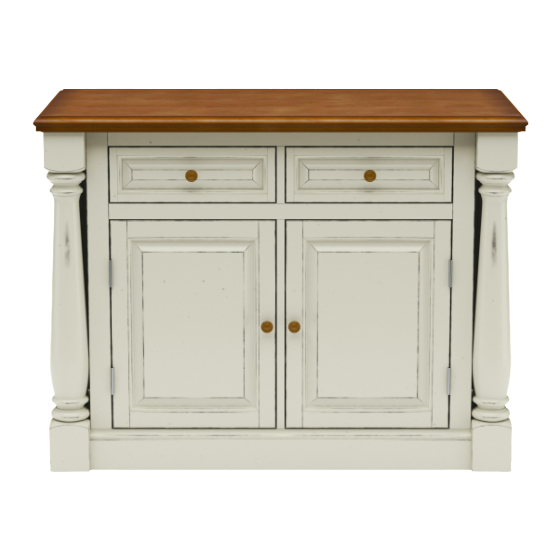
Kitchen Island
C.
D.
Middle Panel
1 Pc.
K.
Back Panel
2 Pcs.
Adjustable Pin
16 pcs. (+1 extra)
1"
Round Head Screw
16 pcs. (+1 extra)
Phillips screwdriver,
E.
Front Rail
1 Pc.
F.
Front Rail
1 Pc.
G.
Back Rail
1 Pc.
H.
Back Rail
1 Pc.
L.
Back Upright
1 Pc.
Cam Lock
Cam Lock Screw
15 pcs. (+2 extra)
15 pcs. (+1 extra)
M6x35
Head Cap Bolt
Magnet
20 pcs. (+1 extra)
2 pcs.
Level
888-680-7460, 877-831-0319
Patent 8,584,600 B2
M.
Door
1 Pc.
O.
Drawer
2 Pcs.
Refer to later page(s) of these
instructions for drawer assembly.
1/2"
3/4"
Round Head Screw
Round Head Screw
4 pcs. (+1 extra)
8 pcs. (+1 extra)
M4x25
Machine Screw
Knob
Flat Washer
4 pcs.
4 pcs.
8 pcs. (+1 extra)
I.
Shelf
4 Pcs.
N.
Door
1 Pc.
Advertisement

Subscribe to Our Youtube Channel
Related Manuals for Homestyles 20 05020 0941


Summary of Contents for Homestyles 20 05020 0941
- Page 1 4 pcs. 4 pcs. 8 pcs. (+1 extra) Cartons 20 05020 0942 and 20 05008 0943 or 20 05009 0943 are also needed for assembly. Tool(s) required for assembly: Phillips screwdriver, Level Home Styles Customer Service: www.homestyles-furniture.com, servicedesk@homestyles-furniture.com, 888-680-7460, 877-831-0319...
- Page 2 Assembly Instructions 2/9 IMPORTANT Ÿ Use a soft cloth between these parts and the floor. Ÿ Do not use power tools above 8 volts to assemble. Ÿ Do not tighten all the bolts until each part is properly assembled. Ÿ The unit must be level to work properly.
- Page 3 Assembly Instructions 3/9 STEP 3 Attach Middle Panel (D) to Back Rails (G), (H) and Back Upright (L) with Cam Locks. (See Figure 3) Slide Back Panels (K) into position. Attach Front Rails (E) and (F) to unit with Cam Locks. Cam Lock Figure 3 Cam Lock...
- Page 4 Assembly Instructions 4/9 STEP 5 Attach Base (J) to unit with Cam Locks, Flat Washers and Head Cap Bolts. Tighten bolts using Hex Wrench. (See Figure 4) Head Cap Bolt Flat Washer Cam Lock Figure 4 STEP 6 Attach Post Assemblies (P) and (Q) Head Cap Bolt to unit with Head Cap Bolts.
- Page 5 Assembly Instructions 5/9 3/4” Round Head Screw Knob Machine Screw 3/4” Round Head Screw STEP 7 Level unit by adjusting the adjustable levelers on bottom of unit. (See Figure 5) Insert 3/4” Round Head Screws into pre-drilled holes in back of unit, then tighten. Note: Unit must be level before tightening these screws.
- Page 6 Assembly Instructions 6/9 STEP 8 Insert Adjustable Pins into side panels and middle panel at desired level. Slide Shelves (I) into position. Adjustable Pin STEP 9 3/4” Flat Head Screw Place Top (A1) and Top (A2) upside down on a soft cloth. Attach Top (A2) to Top (A1) with 3/4”...
- Page 7 Assembly Instructions 7/9 Drawer (O) STEP 10 Attach Drawer Front (O1) and Drawer Back (O2) to Drawer Side (O3) with 1” Round Head Screws. Roller at back 1” Round Head Screw 1” Round Head Screw STEP 11 Slide Drawer Bottom (O5) into groove. Attach Drawer Side (O4) to unit with 1”...
- Page 8 Assembly Instructions 8/9 Flat Washer Head Cap Bolt STEP 13 Flat Washer Attach Top (A) to unit with Flat Washers and Head Cap Bolts. (See Figure 9) Head Cap Bolt Slide Drawers (O) into position. Figure 9...
- Page 9 Assembly Instructions 9/9 STEP 14 When leaf top is down, it should be oriented vertically. If it is not vertical and adjustment is desired, turn the adjuster on adjuster block on back rail. (See Figure 10) Adjuster Block Figure 10 Top Extension Instructions STEP 15 Lift up leaf top.
- Page 10 Home Styles is under no obligation to provide replacement parts. Parts are not available for fully assembled items nor are parts available for sale. Replacements for missing or damaged hardware or parts may be requested at: www.homestyles-furniture.com/customer-service/replacement-parts Home Styles Customer Service: www.homestyles-furniture.com, servicedesk@homestyles-furniture.com, 888-680-7460, 877-831-0319...
Need help?
Do you have a question about the 20 05020 0941 and is the answer not in the manual?
Questions and answers