GE PACSystems RX3i User Manual
Cep profinet scanner
Hide thumbs
Also See for PACSystems RX3i:
- User manual (169 pages) ,
- Command line interface manual (116 pages) ,
- Application manual (39 pages)

Related Manuals for GE PACSystems RX3i


Summary of Contents for GE PACSystems RX3i
- Page 1 Automation & Controls Programmable Control Products PACSystems* RX3i PACSystems* RX3i CEP PROFINET Scanner User Manual GFK-2883E CEP PROFINET Scanner User Manual GFK-2883E March 2018 For Public Disclosure...
- Page 2 Changes, modifications, and/or improvements to equipment and specifications are made periodically and these changes may or may not be reflected herein. It is understood that GE may make changes, modifications, or improvements to the equipment referenced herein or to the document itself at any time. This document is intended for trained personnel familiar with the GE products referenced herein.
- Page 3 Online technical support and GlobalCare www.geautomation.com/support Additional information www.geautomation.com Solution Provider solutionprovider.ip@ge.com Technical Support If you have technical problems that cannot be resolved with the information in this manual, please contact us by telephone or email, or on the web at www.geautomation.com/support. Americas...
-
Page 4: Table Of Contents
Table of Contents PACSystems* RX3i CEP PROFINET Scanner User Manual GFK-2883E Table of Contents ................................i Table of Figures ................................iv Overview ..............................1 Chapter 1 CEP Carrier ..............................2 CEP Expansion Carrier ..........................2 Specifications ............................3 Controls and Indicators ........................... 4 LEDs on the RX3i CEP Carrier and Expansion Carrier ................ - Page 5 Contents Installation and Mounting ........................23 Chapter 3 Carrier Installation ..........................24 Installation Requirements ..........................24 Installation in Hazardous Areas ......................... 25 Installing an RX3i CEP Carrier on a DIN-rail ................... 26 Removing an RX3i CEP Carrier from a DIN-rail ..................26 Panel Mounting ..............................
- Page 6 Contents Hot Swap of I/O Modules ........................53 Firmware Updates ..........................54 Installing the USB Port Driver ......................55 Diagnostics ............................... 57 Chapter 6 Configuration Faults ..........................58 Version Information ..........................58 Fatal Error Handling ..........................59 Automatic Restart ............................59 Connection Troubleshooting .......................
-
Page 7: Table Of Figures
Contents Table of Figures Figure 1: RX3i CEP Carrier with the Expansion Carrier Connected ....................4 Figure 2: CEP001 Underside View ................................5 Figure 3: Timeline for Successful MRP Ring Repair at 16ms I/O Update Rate ................. 8 Figure 4: CEP001 LEDs ....................................18 Figure 5: Underside of CEP001 Showing Ethernet Ports ........................ -
Page 8: Chapter 1 Overview
Chapter 1 Overview This chapter provides an overview of the RX3i CEP (carrier embedded PROFINET) product for PACSystems RX3i I/O modules and their operation. The RX3i CEP carriers for PACSystems* RX3i I/O modules product line includes the following: Catalog Number... -
Page 9: Cep Carrier
Chapter 1. Overview 1.1 CEP Carrier The RX3i CEP Carrier (IC695CEP001) interfaces a remote node of one RX3i I/O module to a PROFINET I/O Local Area Network (LAN). The RX3i CEP Carrier works as a PROFINET Scanner. It scans the I/O modules installed on it and, if present, the RX3i CEP Expansion Carrier, retrieving input data and providing output data, and exchanges that data on the PROFINET I/O LAN at the configured production rate. -
Page 10: Specifications
Note: For product standards, general operating specifications, and installation requirements, refer to PACSystems RX3i System Manual, GFK-2314. Value does not include the power consumption of the installed I/O modules. When calculating the total power requirements, you will need to add the power consumption of the I/O modules according to the I/O module datasheet. -
Page 11: Controls And Indicators
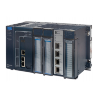
Chapter 1. Overview 1.4 Controls and Indicators Figure 1: RX3i CEP Carrier with the Expansion Carrier Connected LEDs on the RX3i CEP Carrier and Expansion Carrier LEDs provide an immediate visual indication of the RX3i CEP’s operational state and port link status. The LEDs and their operation are described in Chapter 2, LED Operation and Connectors. -
Page 12: Ethernet Port Connections
Chapter 1. Overview Ethernet Port Connections Figure 2: CEP001 Underside View The two external Ethernet ports are on the bottom of the module. Each port on an RX3i CEP Carrier operates independently, so devices that operate at different speeds and/or duplex modes can be attached to the ports. By default, all ports are set for Automatic, which enables auto-negotiation for the widest range of options supported by the port. -
Page 13: Profinet Operation
The PROFINET IO-Supervisor is typically used for commissioning or diagnostics. PROFINET Communications For details about communications on an RX3i PROFINET network, refer to the PACSystems RX3i & RSTi-EP PROFINET I/O Controller Manual, GFK-2571, and to the PACSystems RX3i PROFINET Scanner Manual, GFK-2737. - Page 14 Chapter 1. Overview Bumpless Operation with MRP The RX3i CEP Carrier supports bumpless operation with the GE Automation & Controls PROFINET IO- Controller if specific conditions are met. Bumpless operation means that a single break in an MRP ring will not cause the PROFINET connection to be lost and there is no observed loss and addition of PROFINET I/O Devices while the ring network recovers.
-
Page 15: Figure 3: Timeline For Successful Mrp Ring Repair At 16Ms I/O Update Rate
The minimum I/O rate that is possible for bumpless operation depends on the speed and the type of physical connection being used for the MRP ring ports. The RX3i PROFINET IO Controller supports a specified number of GE Automation & Controls PROFINET I/O devices running at or above the minimum I/O Update Rate listed in the following table. -
Page 16: Supported I/O Modules
Chapter 1. Overview 1.6 Supported I/O Modules The following table indicates the minimum CEP001 firmware version required for compatibility with the listed I/O modules and whether the module can be installed in the RX3i Expansion Carrier CEE001. Earliest Distin- CEE001 Catalog CEP001 Module Description... - Page 17 Chapter 1. Overview Earliest Distin- CEE001 Catalog CEP001 Module Description guishing Comp- Number Compatible Classes atible Version IC694MDL646 16-Circuit Input 24 Vdc Positive / Negative Logic Fast 16 in 1.00 IC694MDL648 16-Circuit Input 48 Vdc Positive / Negative Logic Fast 16 in 2.30 IC694MDL654...
- Page 18 Chapter 1. Overview Earliest Distin- CEE001 Catalog CEP001 Module Description guishing Comp- Number Compatible Classes atible Version IC694MDL754 32-Circuit Output with ESCP None 2.30 IC694MDL916 16-Circuit Output 4A Relay None 1.00 IC694MDL930 8-Circuit Output 4A Relay Isolated 8 out 2.30 IC694MDL931 8-Circuit Output Relay Form BC Isolated 8 out...
- Page 19 Chapter 1. Overview Earliest Distin- CEE001 Catalog CEP001 Module Description guishing Comp- Number Compatible Classes atible Version Analog Mixed Modules ALG IN 4, IC693ALG442 4-Input / 2-Output, Current / Voltage 2.30 ALG OUT 2 ALG IN 4 IC694ALG442 4-Input / 2-Output, Current / Voltage 2.30 ALG OUT 2 Thermocouple Input Modules...
-
Page 20: Compatibility
Proficy Machine Edition version 8.6 SIM 3 or later PACSystems RX3i CPU, IC695CPU315/CPU320/CPE305/CPE310/CPE330/ RX3i CPU Version CRU320, with firmware version 8.50 or later PACSystems RX3i PROFINET IO-Controller, IC695PNC001, with firmware RX3i PNC Version version 2.20 or later Effective with IC695CEP001 Firmware version 2.30, the PACSystems RXi... -
Page 21: Revisions In This Manual
Chapter 1. Overview 1.8 Revisions in this Manual Date Description • Mar- Updated for CPE302 compatibility. 2018 • Corrected all footnotes. • Dec- Documented additional Supported I/O Modules. 2015 • Added support of HART® Pass Through using PROFINET • Added new sections 4.3, Add New I/O Devices &... -
Page 22: Pacsystems Documentation
PACSystems RX3i CEP PROFINET Scanner User Manual GFK-2883 In addition to these manuals, datasheets and product update documents describe individual modules and product revisions. The most recent PACSystems documentation is available on the GE Automation & Controls support website www.geautomation.com/support. -
Page 24: Chapter 2 Led Operation And Connectors
Chapter 2 LED Operation and Connectors This chapter provides detailed description of the carriers’ indicators and ports as follows: • Normal LED operation • Special LED blink patterns • IC695CEP001 ports GFK-2883E March 2018... -
Page 25: Normal Led Operation
Chapter 2. LED Operation and Connectors 2.1 Normal LED Operation IC695CEP001 LEDs Figure 4: CEP001 LEDs Power LEDs The RX3i CEP001 Carrier has two Power LEDs, PWR1 and PWR2 that indicate whether the power is applied and is within range corresponding to the two power sources. Green, ON Power is applied at the minimum specified level Power supply does not have power or has failed... -
Page 26: Power Led (Ic694Cee001)
Chapter 2. LED Operation and Connectors Port LEDs The RX3i CEP001 has two Port LEDs, PRT1 and PRT2 that indicate link speed, link connection and link activity corresponding to the two external Ethernet ports. Green, ON Link connected, 100 Mbps Green, blinking Port active, 100 Mbps Amber, ON... -
Page 27: Special Led Blink Patterns
Chapter 2. LED Operation and Connectors 2.2 Special LED Blink Patterns The RX3i CEP Carrier’s LEDs can operate in tandem to indicate fatal error, module location/identification, and update conditions, as described below. Fatal Error Codes When the RX3i CEP encounters a fatal error, it blinks an error code pattern on the OK LED with an Amber color. In this mode all other LEDs except PWR LEDs flash Amber once to indicate the start of the error code. -
Page 28: Ic695Cep001 Ports
Chapter 2. LED Operation and Connectors 2.3 IC695CEP001 Ports Ethernet Network Ports The two external RJ-45 Ethernet ports are on the underside of the CEP Carrier. Figure 5: Underside of CEP001 Showing Ethernet Ports The RJ-45 ports provide 10/100 Mbps copper interfaces. These ports support CAT5/5e/6 Shielded Twist-pair cabling of up to 100m. -
Page 29: Usb Port
Chapter 2. LED Operation and Connectors USB Port The USB port, located on the bottom of the RX3i CEP Carrier, can be used to connect to a computer for firmware updates for the RX3i CEP Carrier. The USB port accepts a standard USB cable (USB Micro B Male to USB Type A Male, not included). -
Page 30: Chapter 3 Installation And Mounting
Chapter 3 Installation and Mounting This chapter provides RX3i CEP Carrier installation instructions and information for selecting network cabling and connectors as follows: • Carrier installation and mounting − Installing RX3i CEP Carrier on a DIN-rail − Removing RX3i CEP Carrier from the DIN-rail −... -
Page 31: Carrier Installation
12 mm (0.47 in)(fingers, for example). This equates to a NEMA/UL Type 1 enclosure or an IEC60529 IP20 rating providing at least a pollution degree 2 environment. For details about installing RX3i rack systems, refer to the PACSystems RX3i System Manual, GFK-2314. PACSystems* RX3i CEP PROFINET Scanner... -
Page 32: Installation In Hazardous Areas
Chapter 3. Installation and Mounting Installation in Hazardous Areas The following information is for products bearing the UL marking for Hazardous Areas or ATEX marking for explosive atmospheres: Class 1 Division 2 Groups ABCD • This equipment is open-type device and is meant to be installed in an enclosure suitable for the environment that is only accessible with the use of a tool. -
Page 33: Installing An Rx3I Cep Carrier On A Din-Rail
Chapter 3. Installation and Mounting Installing an RX3i CEP Carrier on a DIN-rail The carrier mounts on a standard EN 50022, 35 x 7.5 mm DIN-rail. Conductive (unpainted) finish is required for proper grounding. For best resistance to vibration, the DIN-rail should be installed horizontally on a panel using screws spaced approximately 15 cm (6 in) apart. -
Page 34: Panel Mounting
Chapter 3. Installation and Mounting Panel Mounting For applications requiring maximum or long-term resistance to mechanical vibration and shock, the panel- mounting method is strongly recommended. A minimum panel thickness of 2.4 mm (.093 in) is required. Figure 9: Panel Mount The mounting diagram shown in Figure 9 applies to both the CEP001 Carrier and CEE001 Expansion Carrier. -
Page 35: Installing A Rx3I Cee Expansion Carrier
Chapter 3. Installation and Mounting Installing a RX3i CEE Expansion Carrier ➢ To install a RX3i CEE Expansion Carrier Open the connector cap on the RX3i CEP Carrier. Slide and install the CEE Expansion Carrier along the guide slots on the CEP Carrier. When the Expansion Carrier is aligned with the CEP Carrier, engage the expansion connectors. -
Page 36: Grounding
Chapter 3. Installation and Mounting Grounding All CEP Carriers in a system must be grounded to minimize electrical shock hazard. Failure to do so can result in severe personal injury. Warning The RX3i CEP Carrier and Expansion Carrier each provide two grounding connection contacts: •... -
Page 37: Installing Modules On The Carriers
The insertion and removal of I/O modules is the same as in a RX3i Universal Backplane. For details, refer to, the PACSystems RX3i System Manual, GFK-2314. Do not install a Power Supply module on the CEP or CEE Carrier. Attempting to do so could damage the module and/or the Carrier. -
Page 38: Connecting Power Supplies
Chapter 3. Installation and Mounting 3.3 Connecting Power Supplies The following equipment is needed to connect power supplies: • One 24 Vdc power supply which provides a low voltage/limited current (LVLC) power source (for example, the combination of an isolated DC supply and a fuse, listed 30 Vdc minimum and 3A maximum, connected in series with the input) •... -
Page 39: Adding A Redundant Power Supply
Chapter 3. Installation and Mounting Figure 13: Connecting Power to the RX3i CEP Carrier Adding a Redundant Power Supply Perform the following procedure to add a redundant power supply to a system that is already in operation. ➢ To add a redundant power supply Remove power from the primary power supply to the RX3i CEP carrier Remove the power terminal block from the carrier. -
Page 40: External Switch Vlan Priority Settings
Chapter 3. Installation and Mounting 3.4 External Switch VLAN Priority Settings If a system includes external switches, these switches must be configured to match the VLAN Priority groupings listed below for the RX3i CEP. The PROFINET-I/O specification indicates the VLAN priorities for each type of Ethernet traffic that originates from a PROFINET IO-Device. -
Page 42: Chapter 4 Configuration
Chapter 4 Configuration This chapter provides configuration procedures for RX3i CEP Carriers and their I/O modules in a PROFINET I/O network. For information on configuring the PROFINET I/O Controller and its LAN, refer to the I/O Controller manufacturer’s documentation. Note: To configure RX3i CEP Carriers in an RX3i Controller system, refer to the PACSystems RX3i &... -
Page 43: Configuration Overview
For details on using the Proficy Machine Edition PLC Logic Developer programmer to create and download the configuration for an RX3i PROFINET network and its IO devices, refer to the PACSystems RX3i & RSTi-EP PROFINET I/O Controller Manual, GFK-2571. Basic Configuration Steps The basic configuration steps are: •... -
Page 44: Adding A Rx3I Cep To A Lan
RX3i CEP Carrier is not powered on, connected to the network, or there is a network or configuration issue such that the IO-Controller cannot communicate with the RX3i CEP Carrier. GE Automation & Controls’ IO-Controllers support defaulting inputs to Force Off or Hold Last State values until communication is restored. - Page 45 Chapter 4. Configuration Network Identification The Network Identification parameters of an RX3i CEP Carrier (IP Address, subnet mask, and gateway) should be configured so that each device on the network has a unique IP Address. The IO Controller will configure the network parameters for the RX3i CEP Carrier during the Connect sequence.
-
Page 46: Adding Rx3I I/O Modules To A Remote Node
CEP Carrier. Configuring Modules with Sub-modules Some PACSystems RX3i I/O modules have functionality that must be configured before operation; otherwise Proficy Machine Edition indicates an error on the module. Figure 14: Add Sub-Module for Slot 1 Device To complete the configuration, right click the slot containing the IO Module (Figure 14) and select Change Submodule List. -
Page 47: Figure 15: Configuration Of Multiple Options For Certain Io Modules
Configuring Discrete Modules that have DIP Switches Some PACSystems RX3i discrete output modules have a physical DIP switch that controls the operation of their output circuits when connection to an IO-Controller is lost. A switch selects between Force Off and Hold Last State. -
Page 48: Configuring Module Parameters
Chapter 4. Configuration Configuring Module Parameters After adding PACSystems RX3i modules to the remote IO-Device, their parameters must be configured. For all PACSystems RX3i modules, this includes configuring a set of basic parameters such as reference address. Configuration details for those basic parameters are given on the following pages. If the module has no module-specific parameters, a blank grouping of Module Parameters may be displayed in the Configuration Tool. - Page 49 Chapter 4. Configuration RX3i CEP Configuration Validation Some configuration validation is performed by the RX3i CEP Carrier when the configuration is delivered to it. The following table indicates the configuration validations performed for the indicated modules. If the RX3i CEP Carrier detects an invalid configuration for a given module, the module transitions to module default operation and point faults are energized on the assigned I/O.
- Page 50 For discrete modules, the length of the input /output data is fixed and cannot be edited. Other Data: Some modules have other data areas such as Module Status, ESCP Point Status, or Digital Filter settings. Refer to the PACSystems RX3i System Manual, GFK-2314, for more details about the data of each I/O Module. GFK-2883E...
-
Page 51: Add New I/O Devices
Chapter 4. Configuration 4.3 Add New I/O Devices ➢ To add new I/O Devices: Add a PNC module in the RX3i Rack, right-click on the PNC module, and select Add IO –Device. Figure 16: Hardware Config: Add IO-Device Click Have GSDML. Figure 17: Click on Have GSDML PACSystems* RX3i CEP PROFINET Scanner GFK-2883E... -
Page 52: Figure 18: Browse To And Select Gsdml File
Chapter 4. Configuration Select the GSDML file to be imported and click Open. Figure 18: Browse to and Select GSDML file The GSDML file is added to the list. Select the file and click OK. Figure 19: GSDML Added The CEP module is added under PNC. Figure 20: CEP Node Added GFK-2883E March 2018... -
Page 53: Update Existing I/O Devices
Chapter 4. Configuration 4.4 Update Existing I/O Devices From time to time, updated GSDML files are made available, such as when new features associated with the device are released. The updated GSDML files may be applied by following the instructions in this section. ➢... -
Page 54: Figure 23: List Of Available Gsdml Files
Chapter 4. Configuration Verify the desired GSDML version displays in the drop-down menu. Figure 23: List of Available GSDML files Verify that all the I/O devices to be updated with the new GSDML revision are selected in the menu and click OK. Figure 24: Verify List of Devices Effected by GSDML Change GFK-2883E March 2018... -
Page 55: Assigning Io-Device Names
Chapter 4. Configuration 4.5 Assigning IO-Device Names After the RX3i CEP and other IO-Devices on the LAN have been entered into the configuration, the Discovery and Configuration Protocol (DCP) tool must be used to assign a name to each I/O Device. The name of each device on the LAN must match the hardware configuration in the IO-Controller. -
Page 56: Chapter 5 Operation
Chapter 5 Operation This chapter describes RX3i CEP Carrier startup and restart, input status data, I/O modules replacement while scanning, and firmware update as follows: • Power-up • I/O Scanning • Hot Swap of I/O Modules • Firmware Update • Installing the USB Port Driver GFK-2883E March 2018... -
Page 57: Power-Up
Chapter 5. Operation 5.1 Power-up When power is applied, the RX3i CEP Carrier loads a firmware image. During the power-up process, the CEP Carrier runs diagnostics and initializes its hardware components. After completing power-up sequence, the OK LED changes from being off to solid on green. If a fatal error occurs during powerup, the amber OK LED blinks a unique pattern indicating the nature of the failure. -
Page 58: I/O Scanning
Chapter 5. Operation 5.2 I/O Scanning RX3i CEP Status and Control Data The RX3i CEP Carrier provides 32 bits of input status data and receives 32 bits of output control data. The application program in the IO-Controller system can monitor the input status bits for the RX3i CEP Carrier. The output control bits are reserved for future use and have no function at this time. -
Page 59: Data Coherency
Chapter 5. Operation Data Coherency The RX3i CEP provides coherency at a sub-module basis only. This means that output data from a single IO- Controller for multiple modules in the RX3i CEP Carrier and Expansion Carrier might not be applied by the RX3i CEP during the same output scan. -
Page 60: Hot Swap Of I/O Modules
I/O. Operation must continue to comply with PACSystems Hot Insertion and Removal requirements as documented in the PACSystems RX3i System Manual, GFK-2314. This depends mostly on the timing requirements for physically seating a module. -
Page 61: Firmware Updates
Chapter 5. Operation 5.4 Firmware Updates Note: The RX3i CEP Carrier does not prevent initiation of firmware update when it is actively connected to an IO-Controller. When the RX3i CEP Carrier enters firmware update mode, the RX3i CEP and its modules go to their IO default modes. During the update, the RX3i CEP does not drive module outputs or send inputs to the IO-Controller. -
Page 62: Installing The Usb Port Driver
Chapter 5. Operation 5.5 Installing the USB Port Driver The USB port is only used for firmware updates. USB driver files are provided as part of upgrade packages compatible with the RX3i CEP. With the provided installation files accessible on either a local or network drive, connect the computer’s USB port to the RX3i CEP Carrier’s USB port. -
Page 64: Chapter 6 Diagnostics
Chapter 6 Diagnostics This chapter describes configuration faults, how to check the RX3i CEP Carrier’ version information, fatal error handling, and some common troubleshooting suggestions as follows: • Configuration Faults • Version Information • Fatal Error Handling • Connection Troubleshooting •... -
Page 65: Configuration Faults
0 (indicates the RX3i CEP Carrier itself) with the information for the RX3i CEP Carrier. Refer to the PACSystems RX3i & RSTi-EP PROFINET I/O Controller Manual, GFK-2571, Chapter 3, specifically to the documentation for the I/O Controller and configuration tool to access I&M data. For the RX3i PROFINET IO- Controller, this is available under the Explore PROFINET Networks option in Proficy Machine Edition. -
Page 66: Fatal Error Handling
Problem Indication Action Contact Customer Service. Hardware failure OK LED is off Return the module to GE Automation & Controls Enter boot mode, OK, CONN, PORT1 and PORT2 Update firmware to latest Invalid firmware LED flash green in unison version... -
Page 67: Connection Troubleshooting
Chapter 6. Diagnostics 6.4 Connection Troubleshooting A PROFINET I/O Device can be challenging to troubleshoot if a connection to the I/O Controller will not establish. Below are some suggestions of possible things to consider: • Verify the network cabling. Scan the network using both the DCP and Explore PROFINET Networks tools in Proficy Machine Edition. -
Page 68: Profinet Diagnosis Alarms
Chapter 6. Diagnostics 6.5 PROFINET Diagnosis Alarms The RX3i CEP reports its own non-fatal errors and errors on modules in the remote node using PROFINET Pull/Plug or PROFINET Diagnosis alarms. Diagnosis Alarms indicate any fault conditions other than a module add, loss, or mismatch that an RX3i CEP Carrier needs to communicate to the PROFINET Controller. - Page 69 Module Parameterization configuration due to Configured all settings allowed by Fault one of the GSDML in non-GE parameters being Automation & Controls incorrect. I/O Controllers. Verify field power to the specified module is wired Channel Diagnosis and energized correctly.
- Page 70 Chapter 6. Diagnostics Channel Module or Diagnosis Error Channel Cause Fault Text Recommended Action AlarmType Type Error Engineering Unit change from previous sample to Check the input history to Channel Diagnosis current sample is Negative Rate of Channel understand whether it is Appears/Disappears negative and Change Alarm...
- Page 71 Chapter 6. Diagnostics Channel Module or Diagnosis Error Channel Cause Fault Text Recommended Action AlarmType Type Error There are no corrective actions for this. Automatically Channel Diagnosis Restart after Channel restart after a fatal Successfully restarting Appears/Disappears fatal error. error occurred RX3i CEP module again may eliminate the fault.
- Page 72 Chapter 6. Diagnostics Channel Module or Diagnosis Error Channel Cause Fault Text Recommended Action AlarmType Type Error Channel Channel Diagnosis Loss of Circuit Check communication on Channel communication Appears/Disappears Communication specified channel. failed Verify field power to Channel Diagnosis Group 1 power loss Loss of Group 1 group 1 on the specified Module...
-
Page 74: Appendix A Profinet Specifications
Appendix A PROFINET Specifications Release 2.00 of the RX3i CEP Carrier supports PROFINET V2.3 Class A I/O Device with the clarifications listed in the following table. For version-specific updates, refer to the Important Product Information document provided with your version of the CEP Carrier. A-1 PROFINET Protocol Support RTC –... -
Page 75: Limitations
Appendix A. PROFINET Specifications A-3 Limitations The following features are not supported in release 1.00: RT over UDP IRT Multicast communication DHCP DCP Hello service DNS (Domain Name Service protocol) FastStartUp SNMP Supervisor-AR. Note: Supervisor-DA-AR is supported. (Device Access supported) CBA Substitute Data Only one Input-CR and one Output-CR are supported PACSystems* RX3i CEP PROFINET Scanner... - Page 77 GE Automation and Controls Additional Resources Information Centers For more information, please visit our web site: Headquarters: 1-800-433-2682 or 1-434-978-5100 www.geautomation.com Global regional phone numbers are available on our web site www.geautomation.com Copyright © 2013-2018 General Electric Company. All Rights Reserved *Trademark of General Electric Company.
Need help?
Do you have a question about the PACSystems RX3i and is the answer not in the manual?
Questions and answers