
Related Manuals for MICROWELL DRY 300


Summary of Contents for MICROWELL DRY 300
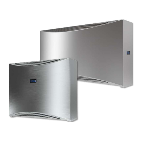
- Page 1 Installation and user manual POOL DEHUMIDIFIER Model: DRY 300 METAL / SILVER DRY 400 METAL / SILVER DRY 500 METAL / SILVER Version: 01/2022...
-
Page 2: Table Of Contents
D R Y 3 0 0 / 4 0 0 / 5 0 0 M e t a l / S i l v e r V01/2022 Thank you, for purchasing a Microwell swimming pool dehumidifier. You have probably chosen the best and most energy efficient dehumidifier for your pool. -
Page 3: Waste Disposal Information
Installation and user manual D R Y 3 0 0 / 4 0 0 / 5 0 0 M e t a l / S i l v e r V01/2022 ......................60 PERATION DURING CONSTRUCTION LIGHT+ ............................60 MICRO WARRANTY CONDITIONS ........................ -
Page 4: Usage Precautions
Installation and user manual D R Y 3 0 0 / 4 0 0 / 5 0 0 M e t a l / S i l v e r V01/2022 • Only authorized person with particular electro-technical qualification can manipulate with unit. •... -
Page 5: Handling Precautions
Installation and user manual D R Y 3 0 0 / 4 0 0 / 5 0 0 M e t a l / S i l v e r V01/2022 • Do not dry wet towels or swimsuits on the unit and do not put other objects on top of it (e.g. -
Page 6: Product Description
Installation and user manual D R Y 3 0 0 / 4 0 0 / 5 0 0 M e t a l / S i l v e r V01/2022 • It is forbidden to freely drop the device on the ground or any hard or rough surface that can lead to a hard impact of the device and scratch the cover. - Page 7 Separate small box glued to Part of the package (white the device (cardboard box) box), is located under the see picture 1 Dry 300 main cover at the fan (Dry300 / 400) or above the capillary on the right side (Dry500)1x...
- Page 8 Installation and user manual D R Y 3 0 0 / 4 0 0 / 5 0 0 M e t a l / S i l v e r V01/2022 3- Built-in digital thermostat 4 - Solenoid valve - valve and and humidistat coil Part of the package (white...
-
Page 9: Description Of Basic Parts
Installation and user manual D R Y 3 0 0 / 4 0 0 / 5 0 0 M e t a l / S i l v e r V01/2022 2 – Screwdriver Vacuum cleaner and Phillips PH2 ladder 5 –... -
Page 10: Fresh Air Supply ( On Demand As Accessory )
Fresh air supply ( on demand as accessory Each MICROWELL DRY dehumidifier has the option of fresh air supply. The air supply is located below the condenser, which effectively heats the incoming fresh air due to heat recovery. The metal fresh air connection is supplied already mounted on the dehumidifier, but towards the inside. -
Page 11: Handling Instructions
Installation and user manual D R Y 3 0 0 / 4 0 0 / 5 0 0 M e t a l / S i l v e r V01/2022 | 1 1 HANDLING INSTRUCTIONS Main humidistat The dehumidifier is switched on and off using a digital humidistat with a display. The built-in humidistat is located in the housing of the device. - Page 12 Installation and user manual D R Y 3 0 0 / 4 0 0 / 5 0 0 M e t a l / S i l v e r V01/2022 | 1 2 User setting HUMIDITY / TEMPERATURE changing ( /* Manufacturer settings) Press SET key for 10secs Temperature manufacturer setting...
- Page 13 Installation and user manual D R Y 3 0 0 / 4 0 0 / 5 0 0 M e t a l / S i l v e r V01/2022 | 1 3 Deviation, correction and other service settings Press SET key for 10secs Displayed immediately Displayed after 10 secs...
- Page 14 Installation and user manual D R Y 3 0 0 / 4 0 0 / 5 0 0 M e t a l / S i l v e r V01/2022 | 1 4 Program setting ( /* Manufacturer settings) TEMPERATURE output type Cooling Heating /*...
- Page 15 Installation and user manual D R Y 3 0 0 / 4 0 0 / 5 0 0 M e t a l / S i l v e r | 1 5 V01/2022 HUMIDITY output type select Humidifying Dehumidifying /* HUMI.
-
Page 16: Backup Humidistat
Installation and user manual D R Y 3 0 0 / 4 0 0 / 5 0 0 M e t a l / S i l v e r | 1 6 V01/2022 Backup humidistat Your dehumidifier is equipped with a built-in mechanical humidistat as standard. On request, it can be equipped with an external wired humidistat, or an external wireless humidistat and thermostat. - Page 17 Installation and user manual D R Y 3 0 0 / 4 0 0 / 5 0 0 M e t a l / S i l v e r V01/2022 | 1 7 Wireless communication takes place in the 868 MHz band, where the emphasis is on the reliability and range of the controller.
-
Page 18: Humidity Control By External Wired Humidistat Eberle
Installation and user manual D R Y 3 0 0 / 4 0 0 / 5 0 0 M e t a l / S i l v e r V01/2022 | 1 8 Location of receiver and antenna A: The receiver is located inside the electrobox and the antenna is located on the outside of it. B: For TTW version / through the wall / we recommend pulling the antenna into the pipe in the wall. -
Page 19: Fan Regulation
Installation and user manual D R Y 3 0 0 / 4 0 0 / 5 0 0 M e t a l / S i l v e r V01/2022 | 1 9 When ordering EBERLE HYG6001/7001, there will be no digital humidistat and thermostat 1401F on the covers and the hole in the cover will be covered with a cover. -
Page 20: Installation Manual
Installation and user manual D R Y 3 0 0 / 4 0 0 / 5 0 0 M e t a l / S i l v e r V01/2022 | 2 0 5. INSTALLATION MANUAL Please note that the screws and dowels supplied with the appliance may only be used on a solid concrete or a brick wall. -
Page 21: Device Location
POOL expected to be present. DRY 300, DRY 400 and DRY 500 WAVE are designed to be installed directly in the pool hall. All models are protected by electrical protection class IP44. - Page 22 Installation and user manual D R Y 3 0 0 / 4 0 0 / 5 0 0 M e t a l / S i l v e r V01/2022 | 2 2 1. In order to be as efficient as possible, the appliance must be installed as high as possible but not completely below the ceiling.
-
Page 23: Device Fixation
Device fixation A DRY 300 / DRY 400 / DRY 500 accessory is a mounting bracket that must be fixed to the wall with the supplied screws and dowels. The device has a self-supporting construction. The axis of the mounting holes is 210 mm lower than the upper edge of the device. - Page 24 – the location can be found on the installation template. 3x DRY 300/400/DRY 500 3 holes 3. You must drill: for the DRY300/400/500 wall console, 2 diery holes for the...
- Page 25 Installation and user manual D R Y 3 0 0 / 4 0 0 / 5 0 0 M e t a l / S i l v e r | 2 5 V01/2022 4. Drill the holes. We recommend vacuuming the dust. 5.
- Page 26 The cover can be removed after loosening 2 screws (DRY 300/400 Wave) or 3 screws (DRY 500 Wave) on the bottom part of the device 9. Pull the lower part of the cover...
- Page 27 Installation and user manual D R Y 3 0 0 / 4 0 0 / 5 0 0 M e t a l / S i l v e r V01/2022 | 2 7 10. In the lower left part, there is a condensate drain hose, which must be inserted into the sewer pipe (rear).
-
Page 28: Condensed Water Drainage
Installation and user manual D R Y 3 0 0 / 4 0 0 / 5 0 0 M e t a l / S i l v e r | 2 8 V01/2022 14. Put the cover back on the device. Follow point 9 in reverse order. 15. - Page 29 Installation and user manual D R Y 3 0 0 / 4 0 0 / 5 0 0 M e t a l / S i l v e r V01/2022 | 2 9 Proper installation of condense hose Improper installation of condense hose CONDENSATE DRAIN Condensate drain Condensate drain...
-
Page 30: Main Power Supply Connection
Connection requirements are: Power supply: 220-240 V / 50 Hz / 1f. Fuse: 16A (DRY 300/400/500) with residual current device (RCD) with a rated residual current not exceeding 30 mA. The main switch of the device must be located outside the pool hall. - Page 31 5.4.2 El. connection of external humidistat and thermostat The connection of the EBERLE HYG6001 (HYG7001) cable remote humidistat is made at the installation site. The manufacturer does not supply the connecting cable. EBERLE HYG6001 connection for DRY 300/400 MAIN ELECTRICAL CONNECTION OF THE DEHUMIDIFIER 230V/50Hz/1f 3x 2.5mm2 CYSY...
- Page 32 230V/50Hz/1f 3x 2.5mm2 CYSY breaker 16A type C circuit breaker 30mA EBERLE HYG7001 connection for DRY 300/400 POTENTIAL-FREE CONTACT - NO / opened normally / - If the air is heated, then C / closed / MAIN ELECTRICAL CONNECTION OF THE...
- Page 33 Installation and user manual D R Y 3 0 0 / 4 0 0 / 5 0 0 M e t a l / S i l v e r | 3 3 V01/2022 Black box from the FRONT of the electrobox EBERLE HYG7001 connection for DRY 500 POTENCIAL-FREE CONTACT...
- Page 34 Models with a mobile stand on the floor are supplied with a flex cord for connecting a socket up to 220-240 V / 50 Hz / 1f. The socket must be designed for humid environments and separately protected: a 16A circuit breaker (DRY 300/400/500) with a residual current device (RCD) with a rated residual current not exceeding 30 mA.
- Page 35 Installation and user manual D R Y 3 0 0 / 4 0 0 / 5 0 0 M e t a l / S i l v e r V01/2022 | 3 5 When using the dehumidifier on a stand, it becomes mobile. This means it is meant to physically move in space.
- Page 36 Installation and user manual D R Y 3 0 0 / 4 0 0 / 5 0 0 M e t a l / S i l v e r V01/2022 | 3 6 Fixed stand – Installation The dehumidifier is designed for placement on a surface with a height deviation of max. 0.5% +/-.
-
Page 37: Lphw Hot Water Insert For Additioal Heating - On Demand
Dehumidifier Cool air Please note that DRY 300/400/500 are not equipped with a thermostat and a potential-free heating contact by standard. If your dehumidifier is equipped with a hot water insert and/or a solenoid valve, you must use a... - Page 38 Installation and user manual D R Y 3 0 0 / 4 0 0 / 5 0 0 M e t a l / S i l v e r V01/2022 | 3 8 Parameters of the solenoid valve: dimension DN 12, operating pressure PN 10, •...
-
Page 39: Electric Heating
Installation and user manual D R Y 3 0 0 / 4 0 0 / 5 0 0 M e t a l / S i l v e r V01/2022 | 3 9 Heat output of heating element LPHW (W) It is recommended to insert a DRY300/400 DRY500... -
Page 40: Defrosting By 4-Way Valve(Dry 300/500)- On Demand
V01/2022 | 4 0 Defrosting by 4-way valve(DRY 300/500)– on demand Defrosting with hot gas allows the dehumidifier to work efficiently at air temperatures as low as 5 ° C. It is designed for demanding operations at low air temperatures. Although the efficiency of the device in terms of extraction rate versus energy consumption at 5 °... - Page 41 Installation and user manual D R Y 3 0 0 / 4 0 0 / 5 0 0 M e t a l / S i l v e r | 4 1 V01/2022 Dehumidifier Air vent 4 x screws Air filter...
- Page 42 Installation and user manual D R Y 3 0 0 / 4 0 0 / 5 0 0 M e t a l / S i l v e r V01/2022 | 4 2 A. Electrical installation FRESH AIR INTAKE WITH AUTOMATIC CONTROL OF BLINDS WASTE AIR EXHAUST FRESH AIR INTAKE...
- Page 43 Installation and user manual D R Y 3 0 0 / 4 0 0 / 5 0 0 M e t a l / S i l v e r V01/2022 | 4 3 Wall Dehumidifier Fresh air adapter (turn out Electric blinds + of the unit) SERVO...
-
Page 44: Technical Data
D R Y 3 0 0 / 4 0 0 / 5 0 0 M e t a l / S i l v e r V01/2022 | 4 4 TECHNICAL DATA Technical data chart* Data Unit DRY 300 DRY 400 DRY 500 METAL/ METAL/ METAL/ SILVER... - Page 45 D R Y 3 0 0 / 4 0 0 / 5 0 0 M e t a l / S i l v e r V01/2022 | 4 5 EL. CONNECTION SCHEME DRY 300/400 – BASIC CONNECTION DRY 300.1 6.1.1...
- Page 46 Installation and user manual D R Y 3 0 0 / 4 0 0 / 5 0 0 M e t a l / S i l v e r V01/2022 | 4 6...
- Page 47 Installation and user manual D R Y 3 0 0 / 4 0 0 / 5 0 0 M e t a l / S i l v e r V01/2022 | 4 7...
- Page 48 Installation and user manual D R Y 3 0 0 / 4 0 0 / 5 0 0 M e t a l / S i l v e r V01/2022 | 4 8...
- Page 49 D R Y 3 0 0 / 4 0 0 / 5 0 0 M e t a l / S i l v e r V01/2022 | 4 9 6.1.2 EL. CONNECTION SCHEME DRY 300/400 – ADVANCED CONNECTION DRY 300.2...
- Page 50 Installation and user manual D R Y 3 0 0 / 4 0 0 / 5 0 0 M e t a l / S i l v e r V01/2022 | 5 0...
- Page 51 Installation and user manual D R Y 3 0 0 / 4 0 0 / 5 0 0 M e t a l / S i l v e r | 5 1 V01/2022...
- Page 52 Installation and user manual D R Y 3 0 0 / 4 0 0 / 5 0 0 M e t a l / S i l v e r V01/2022 | 5 2 6.1.3 EL. CONNECTION SCHEME DRY 500 – BASIC CONNECTION DRY 500.1...
- Page 53 Installation and user manual D R Y 3 0 0 / 4 0 0 / 5 0 0 M e t a l / S i l v e r V01/2022 | 5 3...
- Page 54 Installation and user manual D R Y 3 0 0 / 4 0 0 / 5 0 0 M e t a l / S i l v e r V01/2022 | 5 4...
- Page 55 Installation and user manual D R Y 3 0 0 / 4 0 0 / 5 0 0 M e t a l / S i l v e r V01/2022 | 5 5...
- Page 56 Installation and user manual D R Y 3 0 0 / 4 0 0 / 5 0 0 M e t a l / S i l v e r V01/2022 | 5 6 Note: A1-phase A2 - zero for control of cooperating elements for fresh outdoor air supply - louver slats with servo drive and wall exhaust fan...
- Page 57 Installation and user manual D R Y 3 0 0 / 4 0 0 / 5 0 0 M e t a l / S i l v e r V01/2022 | 5 7 6.1.4 EL. CONNECTION SCHEME DRY 500 – ADVANCED CONNECTION DRY 500.2...
- Page 58 Installation and user manual D R Y 3 0 0 / 4 0 0 / 5 0 0 M e t a l / S i l v e r V01/2022 | 5 8...
-
Page 59: Summer Shutdown
Installation and user manual D R Y 3 0 0 / 4 0 0 / 5 0 0 M e t a l / S i l v e r V01/2022 | 5 9 7 SUMMER SHUTDOWN Users of indoor pools take the opportunity to shut down the dehumidifier for the summer. This is mainly due to favorable weather conditions during the summer - dry and warm weather. -
Page 60: Maintanance Instructions
The DRY300 / 400/500 can be equipped with the unique Microwell microLIGHT + system. It is a built- in LED strip that is located inside the unit. microLIGHT + will signal the current color humidity level. - Page 61 Please contact your reseller or distributor if the warranty should be applied to the dehumidifier. Use the following Microwell disclaimer under warranty. No claim will be accepted if: 1. The dehumidifier was used incorrectly, other than as described in this manual or in violation of this user manual, resp.
- Page 62 Installation and user manual D R Y 3 0 0 / 4 0 0 / 5 0 0 M e t a l / S i l v e r V01/2022 | 6 2 Acidity / pH level: 7,4 +/- 0,4 Total alkalinity, CaCO3 80-120 Total hardness, CaCo3...
- Page 63 Installation and user manual D R Y 3 0 0 / 4 0 0 / 5 0 0 M e t a l / S i l v e r V01/2022 | 6 3...
- Page 64 Installation and user manual D R Y 3 0 0 / 4 0 0 / 5 0 0 M e t a l / S i l v e r V01/2022 | 6 4...
- Page 65 Installation and user manual D R Y 3 0 0 / 4 0 0 / 5 0 0 M e t a l / S i l v e r V01/2022 | 6 5 Notes:...
- Page 66 Installation and user manual D R Y 3 0 0 / 4 0 0 / 5 0 0 M e t a l / S i l v e r V01/2022 | 6 6 Notes:...
- Page 67 Installation and user manual D R Y 3 0 0 / 4 0 0 / 5 0 0 M e t a l / S i l v e r V01/2022 | 6 7 Notes:...
- Page 68 D R Y 3 0 0 / 4 0 0 / 5 0 0 M e t a l / S i l v e r V01/2022 | 6 8 Distributor: Manufacturer: MICROWELL, spol. s r.o. SNP 2018/42, 927 01 Šaľa, Slovakia tel.: +421/31/770 7082 e-mail: microwell@microwell.sk w w w . m i c r o w e l l . e u...
Need help?
Do you have a question about the DRY 300 and is the answer not in the manual?
Questions and answers