Table of Contents
Advertisement
Quick Links
This user's guide provides specifications for the evaluation module (EVM) for TAS5622 and TAS5624
Digital Input Class-D Power Stages with the TAS5538 Digital Audio Processor with PWM Output from
Texas Instruments. The user's guide also describes operation of the EVM and provides design information
including schematic, bill of materials, and PCB layout.
1
1.1
1.2
2
2.1
2.2
2.3
2.4
2.5
2.6
2.7
3
3.1
1
2
3
4
5
6
7
8
9
1
2
3
Related Documentation from Texas Instruments
4
PurePath is a trademark of Texas Instruments.
2
I
C is a trademark of NXP B.V. Corp Netherlands.
SLAU376 - May 2012
Submit Documentation Feedback
..................................................................................................................
...........................................................................................
..........................................................................................................
.................................................................................
................................................................................................
...............................................................................................
...............................................................................................
.......................................................................................
...............................................................................................
.............................................................................................
...........................................................................................................
.................................................................................................
.....................................................................................................
.......................................................................................
...............................................................................................
...........................................................................................
.................................................................................
Copyright © 2012, Texas Instruments Incorporated
TAS5622-TAS5624DDVEVM
Contents
.........................................................................
............................................................................
....................................................................
............................................................................
.....................................................................
List of Figures
........................................................................
List of Tables
.............................................................................
........................................................................
.....................................................................
User's Guide
SLAU376 - May 2012
.....................................
TAS5622-TAS5624DDVEVM
2
5
5
6
6
7
7
7
8
9
11
11
11
12
3
4
5
6
8
9
10
15
16
2
7
11
12
1
Advertisement
Table of Contents

Related Manuals for Texas Instruments TAS5622DDVEVM


Summary of Contents for Texas Instruments TAS5622DDVEVM
-
Page 1: Table Of Contents
This user’s guide provides specifications for the evaluation module (EVM) for TAS5622 and TAS5624 Digital Input Class-D Power Stages with the TAS5538 Digital Audio Processor with PWM Output from Texas Instruments. The user’s guide also describes operation of the EVM and provides design information including schematic, bill of materials, and PCB layout. -
Page 2: Introduction
(The FTC regulation specifies operation in 25°C ambient temperature for one hour at 1/8 specified output power (25.0W per channel for TAS5624DDVEVM, 20.63W per channel for TAS5622DDVEVM) and then for 5 minutes at specified output power (200W per channel for TAS5624DDVEVM, 165W per channel for TAS5622DDVEVM). Then distortion vs. output power can be measured. -
Page 3: Tas5622-Tas5624Ddvevm
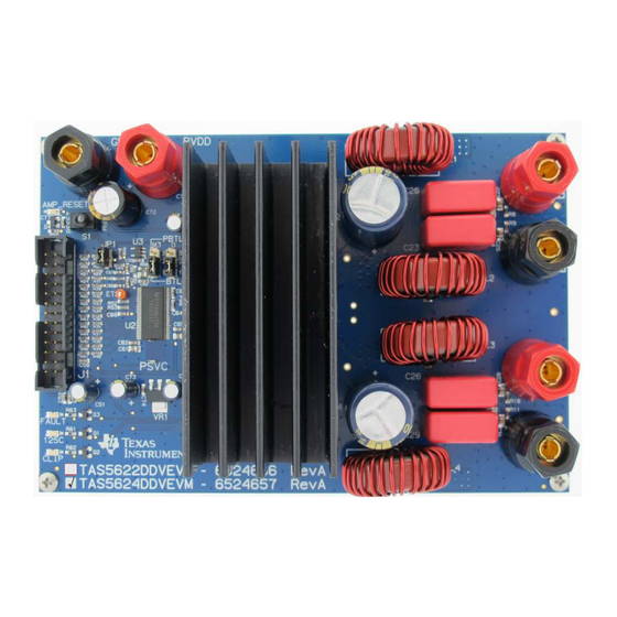
Introduction www.ti.com √ Figure 1. TAS5622-TAS5624DDVEVM SLAU376 – May 2012 TAS5622-TAS5624DDVEVM Submit Documentation Feedback Copyright © 2012, Texas Instruments Incorporated... -
Page 4: Input-Usb Board3
The EVM is delivered with cables and a TI Input-USB Board 3 to connect to an input source and to a PC for control. Refer to the section "Unpacking the EVM" below. TAS5622-TAS5624DDVEVM SLAU376 – May 2012 Submit Documentation Feedback Copyright © 2012, Texas Instruments Incorporated... -
Page 5: Tas5622-Tas5624Ddvevm Features
TI Input - USB Board 3 Power Supply Figure 3. Integrated PurePath Digital™ Amplifier System EVM Physical Structure Physical structure of the TAS5622-TAS5624DDVEVM is illustrated in Figure SLAU376 – May 2012 TAS5622-TAS5624DDVEVM Submit Documentation Feedback Copyright © 2012, Texas Instruments Incorporated... -
Page 6: Quick Setup Guide
(ESD). Customers are advised to observe proper ESD handling precautions when unpacking and handling the EVM, including the use of a grounded wrist strap at an approved ESD workstation. TAS5622-TAS5624DDVEVM SLAU376 – May 2012 Submit Documentation Feedback Copyright © 2012, Texas Instruments Incorporated... -
Page 7: Unpacking The Evm
1 pc. Cable for connecting Input-USB Board 3 to a USB port on a PC for TAS5538 control by software. • If any of these items are missing, contact the nearest Texas Instruments Product Information Center to inquire about a replacement. -
Page 8: Output Configuration Btl And Pbtl
MODE PINS TAS5538 PBTL – BTL (+12 to +36 Vdc) NORMAL RESET INPUT SIGNAL & CONTROL Reset STATUS INTERFACE (J1) LEDs Figure 5. PBTL Mode Configuration TAS5622-TAS5624DDVEVM SLAU376 – May 2012 Submit Documentation Feedback Copyright © 2012, Texas Instruments Incorporated... -
Page 9: Gui Software Installation And Evm Startup
The TAS5622-TAS5624DDVEVM is controlled by the Input-USB Board 3 with the TAS5538 GUI. The TAS5538 GUI provides control of all registers in TAS5538. Download the current version of the GUI zip file "TAS5538_xxxx.zip" from the TAS5622DDVEVM folder or the TAS5624DDVEVM folder on http://www.ti.com to a convenient location on the host PC. -
Page 10: Channel And Master Volume Gui
An SPDIF input may be provided to Input-USB Board 3 by coax to jack COAX or by optical connection to jack OPTO. Alternatively an analog input may be connected to jack ADC1_IN. An analog input will override an SPDIF input. TAS5622-TAS5624DDVEVM SLAU376 – May 2012 Submit Documentation Feedback Copyright © 2012, Texas Instruments Incorporated... -
Page 11: Self-Protection And Fault Reporting
5. PurePath Digital AM Interference Avoidance (SLEA040) 6. Click & Pop Measurements Technique (SLEA044) 7. Power Supply Recommendations for DVD-Receivers (SLEA027) 8. Implementation of Power Supply Volume Control (SLEA038) SLAU376 – May 2012 TAS5622-TAS5624DDVEVM Submit Documentation Feedback Copyright © 2012, Texas Instruments Incorporated... -
Page 12: Appendix A Design Information
CAP SMD0805 CERM 10UFD 16V 10% X5R Digi-Key Murata ROHS CAPACITORS EEU-FC1C470 C1, C51, P11196 CAP 47UFD 16V RAD ALUM ELEC FC ROHS Digi-Key Panasonic C73, C75 Design Information SLAU376 – May 2012 Submit Documentation Feedback Copyright © 2012, Texas Instruments Incorporated... - Page 13 360-1758 SWITCH THRU SPDT STRAIGHT ULTRA Digi-Key MINIATURE ROHS BINDING POSTS 5018-0 GND, LOUT-, 565-5018-0 BINDING POST, BLACK 60V 30A GOLD Mouser Pomona ROUT- ROHS SLAU376 – May 2012 Design Information Submit Documentation Feedback Copyright © 2012, Texas Instruments Incorporated...
- Page 14 CR1, CR2, CR3, CR4, L+, L-, OA, OB, OC, OD, R+, R-, PVDD_AB, PVDD_CD, M1, M2, GNDx2, PSVC EVM Custom Component Vendors TAS5622DDVEVM and TAS5624DDVEVM include inductors and heatsinks from 2 custom component vendors designed specifically for the EVMs. These vendors carry stock for small orders on their shelves..
-
Page 15: Top Composite Pcb Layer
ELECTRICAL TEST: PCB MUST BE ELECTRICAL TESTED COMMENTS: FAB NOTES ARE IN THE DRILL DRAWING FILE EVM PCB Layers Figure 8. Top Composite PCB Layer SLAU376 – May 2012 Design Information Submit Documentation Feedback Copyright © 2012, Texas Instruments Incorporated... -
Page 16: Bottom Composite Pcb Layer
Figure 9. Bottom Composite PCB Layer EVM and Input-USB Board 3 Schematics The EVM and Input-USB Board 3 Schematics are appended to this User's Guide PDF. Design Information SLAU376 – May 2012 Submit Documentation Feedback Copyright © 2012, Texas Instruments Incorporated... - Page 17 TAS5622DDV/TAS5624DDV EVALUATION BOARD 4700pfd/50V 4700pfd/50V 0603 0603 AVDD 0.047ufd/16V 0.047ufd/16V 0603 0603 0603 0603 +3.3V 0603 +3.3V 10ufd/16V 0.1ufd/16V 0805 0603 0.1ufd/16V 0603 0.1ufd/16V A842 0603 0603 AVSS INPUT-USB +3.3V BOARD 2 0.1ufd/16V +3.3V 0603 0603 TPS3825-33DBVT SOT23-DBV5 15.0K 200ms 0603 Orange TAS5622...
- Page 18 TAS5622DDV/TAS5624DDV EVALUATION BOARD +12V 0603 0.1ufd/16V 0603 +12V 0603 0.1ufd/16V 0603 FROM ON/RESET CONTROL 0.033ufd/50V 1.0ufd/50V 0603 0805 OUT_A LEFT 30.0K 7uH/12A 0603 Output +3.3V PVDD_AB MA5173-AE 0.68ufd/250V 1000pfd/100V 0.01ufd/100V PVDD MKP4-15 1206 0805 FROM 0603 LOUT+ MODULATOR 0603 1000ufd/50V LOUT- 0.033ufd/50V 0603...
- Page 19 TAS5622DDV/TAS5624DDV EVALUATION BOARD 5V TO 3.3V DC-DC CONVERTER MAIN POWER IN HARDWARE STAND PVDD +3.3V OFFS M3x8 M3x8 M3x8 M3x8 TLV1117-33 PVDD VOUT HEAT 3.3V 800mA SINK 0.01ufd/100V 1.0ufd/50V 47ufd/50V SOT223-DCY 0805 0805 0.1ufd/16V 0.1ufd/16V M3x8 M3x8 47ufd/16V 47ufd/16V Black M3x25 M3x25 M3x25...
- Page 20 TAS5622DDV/TAS5624DDV EVALUATION BOARD REVISION HISTORY REVISION DESCRIPTION DATE APPROVAL INITIAL RELEASE MARCH 7, 2012 SCH REV PCB REV PAGE INFO: REVISION HISTORY DATE MARCH 7, 2012 SHEET DESIGN LEAD STEPHEN CRUMP EDGE # TAS5622-6524656 / TAS5624-6524657 FILENAME TAS5622-TAS5624DDVEVM_RevA.sbk DRAWN BY...
- Page 21 1.) These preliminary evaluation schematics are intended for use for PRELIMINARY ENGINEERING DEVELOPMENT AND EVALUATION PURPOSES ONLY and are not considered by Texas Instruments to be fit as a basis for establishing production products or systems. This information may be incomplete in several respects, including but not limited to information relating to required design, marketing, and/or manufacturing-related protective considerations and product safety measures typically found in the end-product incorporating the goods.
- Page 22 INPUT-USB BOARD #3 +3.3VD4 4.7K FROM EVMs ACTIVITY SOT23-DBV3 +3.3V-USB +3.3V-USB R404 SDIN C100 R101 0805 Yellow R100 10.0K 0.1ufd/16V 0603 0603 10.0K EPROM 0603 0603 R110 SDA-USB +3.3V-USB TO EVMs 4.99K 0603 SOP8-D(SOIC) R111 SCL-USB +3.3V-USB 4.99K C101 0603 MiniB USB INPUT R112 R102...
- Page 23 INPUT-USB BOARD #3 R202 COAX 1.0M 0603 +3.3VD1 SPDIF +3.3VD1 INV1 4.7K SOT23-DBV3 C200 R201 C201 0.047ufd/16V R200 0603 1.0ufd/10V SPDIF-LOCK 0603 0603 +3.3VD1 SN74LVC1GU04DBV 0805 0603 SOT23-DBV5 R204 Blue 7.50K C203 0603 R211 C202 +3.3VD1 1.0ufd/10V 0603 0603 C205 0.047ufd/16V INV2 0603...
- Page 24 INPUT-USB BOARD #3 JP300 (ADC1) C301 ANALOG R305 R307 +3.3V 4.99K 4.7 1/4W 1.0ufd/16V INPUTS C300 C302 C311 C310 0805 0603 R306 0603 0603 4.99K 470pfd/50V 0.022ufd/25V 0.1ufd/16V 10ufd/10V 0603 ADC MUXES TO I2S 0603 0603 R311 0603 0805 +3.3VD2 JP301 ADC1-IN C348...
- Page 25 INPUT-USB BOARD #3 +3.3VD4 +3.3VD4 +3.3VD4 +3.3VD4 +3.3VD4 +3.3VD4 MUTE SHUT R400 FAULT INV3 C402 C404 4.7K 4.7K 4.7K 10.0K 0603 MUTE DOWN R403 SOT23-DBV3 SOT23-DBV3 SOT23-DBV3 FROM 0.1ufd/16V 0.1ufd/16V 0603 0603 SHUTDOWN FAULT 0805 Yellow R405 R406 R407 C400 C401 0603 SYSTEM...
- Page 26 INPUT-USB BOARD #3 MAIN POWER IN +12V +3.3V +12V +12V Green Green Green 3.3V ES2AA 0805 0805 0805 50V 2A 220ufd/16V 13.0K 0603 0603 0603 Black +3.3VD1 PVDD TO 5V SWITCHER +3.3V 4.7 1/4W SPDIF 0805 +12V BOOT 10ufd/10V 15uH 0805 0.01ufd/50V DG6045C...
- Page 27 INPUT-USB BOARD #3 REVISION HISTORY REVISION DESCRIPTION DATE APPROVAL INITIAL RELEASE JULY 12, 2011 SCH REV PCB REV PAGE INFO: REVISION HISTORY DATE JULY 12, 2011 SHEET DESIGN LEAD TUAN LUU EDGE # 6527708 FILENAME InputUsbBoard3.sbk DRAWN BY...
- Page 28 1.) These preliminary evaluation schematics are intended for use for PRELIMINARY ENGINEERING DEVELOPMENT AND EVALUATION PURPOSES ONLY and are not considered by Texas Instruments to be fit as a basis for establishing production products or systems. This information may be incomplete in several respects, including but not limited to information relating to required design, marketing, and/or manufacturing-related protective considerations and product safety measures typically found in the end-product incorporating the goods.
- Page 29 Any exceptions to this are strictly prohibited and unauthorized by Texas Instruments unless user has obtained appropriate experimental/development licenses from local regulatory authorities, which is responsibility of user including its acceptable authorization.
- Page 30 FCC Interference Statement for Class B EVM devices This equipment has been tested and found to comply with the limits for a Class B digital device, pursuant to part 15 of the FCC Rules. These limits are designed to provide reasonable protection against harmful interference in a residential installation. This equipment generates, uses and can radiate radio frequency energy and, if not installed and used in accordance with the instructions, may cause harmful interference to radio communications.
- Page 31 Also, please do not transfer this product, unless you give the same notice above to the transferee. Please note that if you could not follow the instructions above, you will be subject to penalties of Radio Law of Japan. Texas Instruments Japan Limited (address) 24-1, Nishi-Shinjuku 6 chome, Shinjuku-ku, Tokyo, Japan http://www.tij.co.jp...
- Page 32 FDA Class III or similar classification, then you must specifically notify TI of such intent and enter into a separate Assurance and Indemnity Agreement. Mailing Address: Texas Instruments, Post Office Box 655303, Dallas, Texas 75265 Copyright © 2012, Texas Instruments Incorporated...
- Page 33 Any exceptions to this are strictly prohibited and unauthorized by Texas Instruments unless user has obtained appropriate experimental/development licenses from local regulatory authorities, which is responsibility of user including its acceptable authorization.
- Page 34 FCC Interference Statement for Class B EVM devices This equipment has been tested and found to comply with the limits for a Class B digital device, pursuant to part 15 of the FCC Rules. These limits are designed to provide reasonable protection against harmful interference in a residential installation. This equipment generates, uses and can radiate radio frequency energy and, if not installed and used in accordance with the instructions, may cause harmful interference to radio communications.
- Page 35 Also, please do not transfer this product, unless you give the same notice above to the transferee. Please note that if you could not follow the instructions above, you will be subject to penalties of Radio Law of Japan. Texas Instruments Japan Limited (address) 24-1, Nishi-Shinjuku 6 chome, Shinjuku-ku, Tokyo, Japan http://www.tij.co.jp...
- Page 36 FDA Class III or similar classification, then you must specifically notify TI of such intent and enter into a separate Assurance and Indemnity Agreement. Mailing Address: Texas Instruments, Post Office Box 655303, Dallas, Texas 75265 Copyright © 2012, Texas Instruments Incorporated...
- Page 37 IMPORTANT NOTICE Texas Instruments Incorporated and its subsidiaries (TI) reserve the right to make corrections, enhancements, improvements and other changes to its semiconductor products and services per JESD46, latest issue, and to discontinue any product or service per JESD48, latest issue.
- Page 38 Mouser Electronics Authorized Distributor Click to View Pricing, Inventory, Delivery & Lifecycle Information: Texas Instruments TAS5624ADDVEVM...
Need help?
Do you have a question about the TAS5622DDVEVM and is the answer not in the manual?
Questions and answers