Table of Contents
Advertisement
Quick Links
This manual describes the operation of the TAS5731EVM to evaluate the performance of the TAS5731
integrated digital audio power amplifier. The main contents of this document are:
•
Details on how to properly connect a TAS5731 Evaluation Module (EVM) and the details of the EVM.
•
Details on how to install and use the GUI to program the TAS5731EVM.
•
Quick-start guide for the common modes in which the TAS5731EVM can be used.
•
Details on how to use the audio processing features like EQ and DRC.
......................................................................................................................
1
1.1
....................................................................................................................
2
2.1
2.2
3
3.1
3.2
3.3
3.4
3.5
3.6
3.7
4
4.1
4.2
4.3
5
5.1
5.2
5.3
5.4
1
2
3
4
5
6
7
8
9
10
11
12
SLOU331A - December 2011 - Revised August 2014
This datasheet has been downloaded from
TAS5731EVM Evaluation Module
.....................................................................................................
................................................................................................
.....................................................................................................
.....................................................................................
.............................................................................................
................................................................................................
.........................................................................................
..............................................................................
..........................................................................................
..........................................................................................
............................................................................................................
.....................................................................................................
...................................................................................
....................................................................................
........................................................................................
....................................................................................................
List of Figures
......................................................................................
................................................................................................
..............................................................................
..............................................................................................................
...............................................................................................................
.............................................................................................
.................................................................................................
........................................................................................
................................................................................
SLOU331A - December 2011 - Revised August 2014
Contents
......................................................................
......................................................................
.................................................................
.......................................................................
.....................................................................
.....................................................................
........................................................
http://www.digchip.com
User's Guide
at this
page
2
3
4
4
7
8
9
10
11
13
14
16
16
18
18
18
18
19
19
19
20
21
2
3
4
5
6
6
8
9
10
11
11
12
1
Advertisement
Table of Contents

Subscribe to Our Youtube Channel
Related Manuals for Texas Instruments TAS5731EVM


Summary of Contents for Texas Instruments TAS5731EVM
-
Page 1: Table Of Contents
User's Guide SLOU331A – December 2011 – Revised August 2014 TAS5731EVM Evaluation Module This manual describes the operation of the TAS5731EVM to evaluate the performance of the TAS5731 integrated digital audio power amplifier. The main contents of this document are: •... -
Page 2: Overview
TAS5731EVM Bill Of materials (BOM) Overview The TAS5731 evaluation module demonstrates the TAS5731 device from Texas Instruments. The TAS5731 combines a high-performance PWM processor with a class-D audio power amplifier. This EVM can be configured with two single-ended speakers with a BTL subwoofers (2.1) or two bridge-tied speakers (BTL) (2.0). -
Page 3: Tas5731Evm And Mc57Xxpsia Features
• Double-sided, plated-through PCB, 1oz copper, 2mm • Access to control signal gain and data format through EVM-software GUI SLOU331A – December 2011 – Revised August 2014 TAS5731EVM Evaluation Module Submit Documentation Feedback Copyright © 2011–2014, Texas Instruments Incorporated... -
Page 4: Installation
Speakers or Loads for outputs The following sections describe the TAS5717LEVM board in regards to power supply (PSU) and system interfaces. TAS5731EVM Evaluation Module SLOU331A – December 2011 – Revised August 2014 Submit Documentation Feedback Copyright © 2011–2014, Texas Instruments Incorporated... -
Page 5: Connecting Tas5731Evm To Mc57Xxpsia
When connecting a speaker in BTL mode, connect the speaker’s two terminals across two outputs on the TAS5731EVM (A and B or C and D). Note that the EVM is setup to use only channels A and B in the SE mode, for a real application; however, any of the channels can be setup for SE mode operation. -
Page 6: Btl Connection
MC57xxPSIA board facilitates the connection between a host computer and the device. The EVM USB circuit is powered by the 5V USB line of the host PC and is independent of the power supplies available on the board. The USB device that is used is a TAS1020B from Texas Instruments. 2.1.5... -
Page 7: Software Installation
PVDD power supply. Software Installation Download the TAS57X1 GDE from the TI Web site, located on the TAS5731EVM product page. The TI Web site always has the latest release and any updates to versions of the GUI. Execute the GUI install program, Setup.exe. Once the program is installed, the program group and shortcut icon is created in Start →... -
Page 8: Using The Gui Software
Processing (DAP) flow of the TAS5731, taken from the TAS5731 data sheet is shown in Figure Figure 7. TAS5731 DAP Block Diagram TAS5731EVM Evaluation Module SLOU331A – December 2011 – Revised August 2014 Submit Documentation Feedback Copyright © 2011–2014, Texas Instruments Incorporated... -
Page 9: Setting The Ppsi2C Environment Variable
3. In the New User Variable Window, enter the text PPSI2C as variable name, and 34 as the variable value. SLOU331A – December 2011 – Revised August 2014 TAS5731EVM Evaluation Module Submit Documentation Feedback Copyright © 2011–2014, Texas Instruments Incorporated... -
Page 10: Launching The Gui Interface
Figure 9. Environment Variable and User Variable Window Launching the GUI interface The GUI interface can be opened by clicking on the ‘TAS57X1 GDE’ icon under the Texas Instruments Inc title in the start program menu. NOTE: PPSI2C variable should be set before the GUI interface (or the memory tool) is opened. If the GUI was opened prior to setting the environment variable (Step-1), the GUI interface should be closed and re-opened. -
Page 11: Initializing The Device
To initiate the GUI control, the first step is to ‘Connect’ the GUI. To do this, scroll to the ‘Target’ section of the menu and click on Connect (as shown in Figure SLOU331A – December 2011 – Revised August 2014 TAS5731EVM Evaluation Module Submit Documentation Feedback Copyright © 2011–2014, Texas Instruments Incorporated... -
Page 12: Initiating Connect From The Target Menu
GUI window. After completing these basic operations, the device should now be streaming audio. Figure 13. Toggling Shut-Down and Mute States TAS5731EVM Evaluation Module SLOU331A – December 2011 – Revised August 2014 Submit Documentation Feedback Copyright © 2011–2014, Texas Instruments Incorporated... -
Page 13: Using Eq Function
Finally, when the APPLY button is clicked, the Bi-Quad registers of the device are updated with the programmed settings. SLOU331A – December 2011 – Revised August 2014 TAS5731EVM Evaluation Module Submit Documentation Feedback Copyright © 2011–2014, Texas Instruments Incorporated... -
Page 14: Using The Drc Function
DRC-1, with the user programmable inputs highlighted. The plot on the right estimates the output vs. input level corresponding to the user input(s). TAS5731EVM Evaluation Module SLOU331A – December 2011 – Revised August 2014 Submit Documentation Feedback Copyright © 2011–2014, Texas Instruments Incorporated... -
Page 15: Tas57Xx Gui Drc Customization Tool
‘Time Constants’ in DRC customization tool. The time-constant window snap-shot is shown Figure Figure 18. DRC Time Constants Window SLOU331A – December 2011 – Revised August 2014 TAS5731EVM Evaluation Module Submit Documentation Feedback Copyright © 2011–2014, Texas Instruments Incorporated... -
Page 16: Using The Mixer And Scaler Nodes
20), or can also be launched stand-alone even when the GUI window is not opened, through the Windows → All-Programs → Texas Instruments Inc → I2C Memory tool option. The stand-alone capability is especially convenient when an existing I2C file needs to loaded to update device registers or when performing I2C debug. -
Page 17: I2C Memory Tool
Using the GUI Software www.ti.com Figure 20. I2C Memory Tool SLOU331A – December 2011 – Revised August 2014 TAS5731EVM Evaluation Module Submit Documentation Feedback Copyright © 2011–2014, Texas Instruments Incorporated... -
Page 18: Jumpers And Control Utilities On Mc57Xxpsia Board
LED3: RCA connection made LED4: Optical connection made LED5: SPDIF signal locked LED6: Not Populated LED7: PDN switch (S4) is asserted TAS5731EVM Evaluation Module SLOU331A – December 2011 – Revised August 2014 Submit Documentation Feedback Copyright © 2011–2014, Texas Instruments Incorporated... -
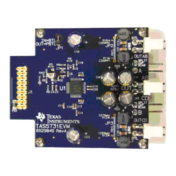
Page 19: Board Layouts, Schematic, And Bill Of Materials
Board Layouts, Schematic, and Bill of Materials www.ti.com Board Layouts, Schematic, and Bill of Materials This section contains the TAS5731EVM board layouts, schematic, and the bill of materials (BOM). TAS5731EVM Board Layouts Figure 21 illustrates the TAS5731EVM top composite assembly. -
Page 20: Tas5731Evm Schematic
BTL = BRIDGE TIED LOAD PGND PBTL = PARALLEL BRIDGE TIED LOAD PGND PGND PGND PGND Figure 23. TAS5731EVM Schematic TAS5731EVM Evaluation Module SLOU331A – December 2011 – Revised August 2014 Submit Documentation Feedback Copyright © 2011–2014, Texas Instruments Incorporated... -
Page 21: Bill Of Materials
Board Layouts, Schematic, and Bill of Materials www.ti.com Bill of Materials Table 1 lists the BOM for this EVM. Table 1. TAS5731EVM Bill Of materials (BOM) Item Manu Part Num Ref Designators Vendor Partnum Description Vendor Manu TAS5731MPHP TAS5731MPHP 20W DIGAMP WITH DAP HTQFP48-PHP ROHS... - Page 22 • Changed contents of the BOM. NOTE: Page numbers for previous revisions may differ from page numbers in the current version. Revision History SLOU331A – December 2011 – Revised August 2014 Submit Documentation Feedback Copyright © 2011–2014, Texas Instruments Incorporated...
- Page 23 ADDITIONAL TERMS AND CONDITIONS, WARNINGS, RESTRICTIONS, AND DISCLAIMERS FOR EVALUATION MODULES Texas Instruments Incorporated (TI) markets, sells, and loans all evaluation boards, kits, and/or modules (EVMs) pursuant to, and user expressly acknowledges, represents, and agrees, and takes sole responsibility and risk with respect to, the following: 1.
- Page 24 RADIO FREQUENCY REGULATORY COMPLIANCE INFORMATION FOR EVALUATION MODULES Texas Instruments Incorporated (TI) evaluation boards, kits, and/or modules (EVMs) and/or accompanying hardware that is marketed, sold, or loaned to users may or may not be subject to radio frequency regulations in specific countries.
- Page 25 Les types d'antenne non inclus dans cette liste, ou dont le gain est supérieur au gain maximal indiqué, sont strictement interdits pour l'exploitation de l'émetteur. Mailing Address: Texas Instruments, Post Office Box 655303, Dallas, Texas 75265 Copyright © 2014, Texas Instruments Incorporated spacer Important Notice for Users of EVMs Considered “Radio Frequency Products”...
- Page 26 IMPORTANT NOTICE Texas Instruments Incorporated and its subsidiaries (TI) reserve the right to make corrections, enhancements, improvements and other changes to its semiconductor products and services per JESD46, latest issue, and to discontinue any product or service per JESD48, latest issue.
Need help?
Do you have a question about the TAS5731EVM and is the answer not in the manual?
Questions and answers