Advertisement
Quick Links
This user's guide describes the operation of the TAS5753MD evaluation module (EVM). The EVM is
connected to the PurePath™ Console Motherboard (PPCMB) and is configured using PurePath Console 3
(PPC3) software. Visit the
The main contents of this document are:
•
Details for properly connecting a TAS5753MD evaluation module (EVM) and the details of the EVM
•
Start-up procedure using PurePath Console 3 (PPC3) software with the correct plugin for the EVM
•
Quick-start guide for the common modes in which the TAS5753MDEVM is used
Throughout this document, the abbreviation EVM and the term evaluation module are synonymous with
the TAS5753MDEVM evaluation module, unless otherwise noted.
space
space
......................................................................................................................
1
Overview
....................................................................................................................
2
EVM Setup
3
Using the TAS5753MDEVM with PurePath Console 3
4
Board Layout, Bill of Materials, and Schematic
1
TAS5753MD Evaluation Board
2
Evaluation Module and PurePath Console Motherboard Connection
3
TAS5753MD Application in PurePath Console 3
4
TAS5753MD Application Home Window
5
TAS5753MDEVM Audio Processing Windows
6
Equalizer Window
7
Multiband AGL – Three-Band Crossover
8
Full-Band AGL
9
TAS5753MDEVM
10
TAS5753MD Layout
11
Bottom Layer Thermal Flow
12
TAS5753MDEVM Optional Features
13
TAS5753MDEVM Top Composite
14
TAS5753MDEVM Top Layer
15
TAS5753MDEVM Ground Layer
16
TAS5753MDEVM Power Layer
17
TAS5753MDEVM Bottom Layer
18
TAS5753MDEVM Bottom Composite
19
TAS5753MDEVM Stereo Device
20
TAS5753MDEVM Mono Device
21
TAS5753MDEVM PPCMB and Power Supply Connection
PurePath is a trademark of Texas Instruments.
SLAU683 – May 2016
Submit Documentation Feedback
e2e Audio Amplifiers
............................................................................................
.................................................................................
............................................................................................................
.................................................................................
..............................................................................................................
..........................................................................................................
.......................................................................................................
..............................................................................................
....................................................................................
.......................................................................................
.............................................................................................
.........................................................................................
..........................................................................................
..........................................................................................
...................................................................................
.........................................................................................
..........................................................................................
Copyright © 2016, Texas Instruments Incorporated
TAS5753MD Evaluation Module
forum for questions and other support issues.
Contents
.................................................................
........................................................................
List of Figures
................................................
........................................................................
..........................................................................
...........................................................
User's Guide
SLAU683 – May 2016
TAS5753MD Evaluation Module
2
3
4
14
2
3
4
5
7
8
9
11
14
14
15
15
16
16
17
17
18
18
21
22
23
1
Advertisement

Subscribe to Our Youtube Channel
Related Manuals for Texas Instruments TAS5753MD


Summary of Contents for Texas Instruments TAS5753MD
- Page 1 SLAU683 – May 2016 TAS5753MD Evaluation Module This user’s guide describes the operation of the TAS5753MD evaluation module (EVM). The EVM is connected to the PurePath™ Console Motherboard (PPCMB) and is configured using PurePath Console 3 (PPC3) software. Visit the e2e Audio Amplifiers forum for questions and other support issues.
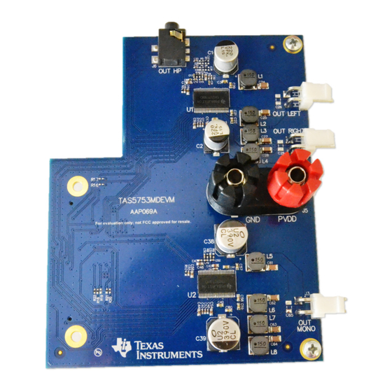
- Page 2 Overview The TAS5753MD evaluation module showcases the latest TI digital input Class-D open-loop amplifiers. The TAS5753MD is an I²S input Class-D amplifier with audio processing features and integrated headphone/line driver. The EVM is configured in Two-Device 2.1 mode with one stereo device using bridge tied load for left and right channels and one mono device configured for mono applications, such as higher power full-range speakers or subwoofers.
- Page 3 Power supply (8 V to 26.4 V) • Audio Source (Analog, USB, Optical) • Micro type-B USB cable • PurePath Console 3.xx GUI running on a PC SLAU683 – May 2016 TAS5753MD Evaluation Module Submit Documentation Feedback Copyright © 2016, Texas Instruments Incorporated...
- Page 4 TAS5753MD application. When opening the TAS5753MD application, a file window appears offering the option to load a previously saved configuration file, start a new configuration or continue the last session.
- Page 5 TAS5753MD Application Features The Home window is displayed when the TAS5753MD application is initialized. Several evaluation and integration options are available. TI recommends using the application walkthrough by clicking on the question mark icon available next to the page name in all pages. The application walkthrough feature provides guidance through various sections in the selected page and displays comments explaining the sections of the page.
- Page 6 The option to save the changes made during the audio tuning using the snapshot feature of PPC3 is also available. TAS5753MD Evaluation Module SLAU683 – May 2016 Submit Documentation Feedback Copyright © 2016, Texas Instruments Incorporated...
- Page 7 Audio I/O shortcut This section shows the audio source and sampling frequency that is used to generate the I²S input for the TAS5753MD amplifiers. The user is redirected to the main Audio I/O window after clicking this button. Audio Player The Audio Player is used to play audio tracks available in the PC and perform various tuning operations.
- Page 8 “Ganged” box. Phase, Group Delay, Impulse Response, and pole/zero charts are available as well for the analysis of the equalizer response. TAS5753MD Evaluation Module SLAU683 – May 2016 Submit Documentation Feedback Copyright © 2016, Texas Instruments Incorporated...
- Page 9 Using the TAS5753MDEVM with PurePath Console 3 www.ti.com Multiband AGL and Full-Band AGL The TAS5753MD features three multiband AGLs, as well as a full-band AGL. The multiband AGL is used as a three-band crossover, having an independent custom configuration for low, high, and mid frequency bands.
- Page 10 Release Rate: When the threshold is raised, this parameter reflects the release rate of the compressed signal. TAS5753MD Evaluation Module SLAU683 – May 2016 Submit Documentation Feedback Copyright © 2016, Texas Instruments Incorporated...
- Page 11 EVM is 0x56, the mono device I²C address is 0x54. Direct I2C has two main tabs, I/O and Log, present in the top right corner of the window. SLAU683 – May 2016 TAS5753MD Evaluation Module Submit Documentation Feedback Copyright © 2016, Texas Instruments Incorporated...
- Page 12 The End System Integration window has three main options for the customer (1) Dump Current State into a Header file, (2) In-System Debugging, and (3) In-System Tuning. TAS5753MD Evaluation Module SLAU683 – May 2016 Submit Documentation Feedback Copyright © 2016, Texas Instruments Incorporated...
- Page 13 SCL, SDA, and GND test points of PPCMB. Limited features of the TAS5753MD application are available in this mode. Disconnect from System Debug Mode by clicking on the Disconnect button on the lower left corner of the window.
- Page 14 PVDD pin connection. The design has wide open areas at the top and bottom part of the amplifier to increase the thermal dissipation of the amplifier. Figure 10. TAS5753MD Layout TAS5753MD Evaluation Module SLAU683 – May 2016 Submit Documentation Feedback Copyright © 2016, Texas Instruments Incorporated...
- Page 15 Join the audio amplifier discussion forum e2e.ti.com for additional design assistance. SLAU683 – May 2016 TAS5753MD Evaluation Module Submit Documentation Feedback Copyright © 2016, Texas Instruments Incorporated...
- Page 16 Board Layout, Bill of Materials, and Schematic www.ti.com TAS5753MDEVM Board Layout Figure 13 through Figure 18 show the PCB layouts. Figure 13. TAS5753MDEVM Top Composite Figure 14. TAS5753MDEVM Top Layer TAS5753MD Evaluation Module SLAU683 – May 2016 Submit Documentation Feedback Copyright © 2016, Texas Instruments Incorporated...
- Page 17 Board Layout, Bill of Materials, and Schematic www.ti.com Figure 15. TAS5753MDEVM Ground Layer Figure 16. TAS5753MDEVM Power Layer SLAU683 – May 2016 TAS5753MD Evaluation Module Submit Documentation Feedback Copyright © 2016, Texas Instruments Incorporated...
- Page 18 Board Layout, Bill of Materials, and Schematic www.ti.com Figure 17. TAS5753MDEVM Bottom Layer Figure 18. TAS5753MDEVM Bottom Composite TAS5753MD Evaluation Module SLAU683 – May 2016 Submit Documentation Feedback Copyright © 2016, Texas Instruments Incorporated...
- Page 19 RES, 47 k, 5%, 0.063 W, 0402 0402 U1, U2 TAS5753MDDCAR Texas Instruments Digital Audio Power Amplifier with EQ, AGL and DCA0048B Headphone/Line Driver , DCA0048B SLAU683 – May 2016 TAS5753MD Evaluation Module Submit Documentation Feedback Copyright © 2016, Texas Instruments Incorporated...
- Page 20 RES, 47 k, 5%, 0.063 W, 0402 0402 R23, R24, R25, R26, CRCW060318R0JNEA Vishay-Dale RES, 18, 5%, 0.1 W, 0603 0603 R27, R28, R29, R30 TAS5753MD Evaluation Module SLAU683 – May 2016 Submit Documentation Feedback Copyright © 2016, Texas Instruments Incorporated...
- Page 21 BTL_R- PGND 0.047µF 15µH PLL_FLTP PGND 4700pF PLL_FLTM DR_OUTA 0.68µF TAS5753MDDCAR DR_OUTB 0.047µF Copyright © 2016, Texas Instruments Incorporated Figure 19. TAS5753MDEVM Stereo Device SLAU683 – May 2016 TAS5753MD Evaluation Module Submit Documentation Feedback Copyright © 2016, Texas Instruments Incorporated...
- Page 22 AGND DGND AVDD_REG1 0.047µF PGND 15µH PLL_FLTP PGND 4700pF PLL_FLTM 0.68µF TAS5753MDDCAR 0.047µF Copyright © 2016, Texas Instruments Incorporated Figure 20. TAS5753MDEVM Mono Device TAS5753MD Evaluation Module SLAU683 – May 2016 Submit Documentation Feedback Copyright © 2016, Texas Instruments Incorporated...
- Page 23 OUTB2 330pF 10.0k OUTC2 DR_OUTB 330pF OUTD2 1µF SNUBBER OPTION Copyright © 2016, Texas Instruments Incorporated Figure 21. TAS5753MDEVM PPCMB and Power Supply Connection SLAU683 – May 2016 TAS5753MD Evaluation Module Submit Documentation Feedback Copyright © 2016, Texas Instruments Incorporated...
- Page 24 STANDARD TERMS AND CONDITIONS FOR EVALUATION MODULES Delivery: TI delivers TI evaluation boards, kits, or modules, including any accompanying demonstration software, components, or documentation (collectively, an “EVM” or “EVMs”) to the User (“User”) in accordance with the terms and conditions set forth herein. Acceptance of the EVM is expressly subject to the following terms and conditions.
- Page 25 FCC Interference Statement for Class B EVM devices NOTE: This equipment has been tested and found to comply with the limits for a Class B digital device, pursuant to part 15 of the FCC Rules. These limits are designed to provide reasonable protection against harmful interference in a residential installation.
- Page 26 【無線電波を送信する製品の開発キットをお使いになる際の注意事項】 開発キットの中には技術基準適合証明を受けて いないものがあります。 技術適合証明を受けていないもののご使用に際しては、電波法遵守のため、以下のいずれかの 措置を取っていただく必要がありますのでご注意ください。 1. 電波法施行規則第6条第1項第1号に基づく平成18年3月28日総務省告示第173号で定められた電波暗室等の試験設備でご使用 いただく。 2. 実験局の免許を取得後ご使用いただく。 3. 技術基準適合証明を取得後ご使用いただく。 なお、本製品は、上記の「ご使用にあたっての注意」を譲渡先、移転先に通知しない限り、譲渡、移転できないものとします。 上記を遵守頂けない場合は、電波法の罰則が適用される可能性があることをご留意ください。 日本テキサス・イ ンスツルメンツ株式会社 東京都新宿区西新宿6丁目24番1号 西新宿三井ビル 3.3.3 Notice for EVMs for Power Line Communication: Please see http://www.tij.co.jp/lsds/ti_ja/general/eStore/notice_02.page 電力線搬送波通信についての開発キットをお使いになる際の注意事項については、次のところをご覧くださ い。http://www.tij.co.jp/lsds/ti_ja/general/eStore/notice_02.page SPACER EVM Use Restrictions and Warnings: 4.1 EVMS ARE NOT FOR USE IN FUNCTIONAL SAFETY AND/OR SAFETY CRITICAL EVALUATIONS, INCLUDING BUT NOT LIMITED TO EVALUATIONS OF LIFE SUPPORT APPLICATIONS.
- Page 27 Notwithstanding the foregoing, any judgment may be enforced in any United States or foreign court, and TI may seek injunctive relief in any United States or foreign court. Mailing Address: Texas Instruments, Post Office Box 655303, Dallas, Texas 75265 Copyright © 2015, Texas Instruments Incorporated...
- Page 28 IMPORTANT NOTICE Texas Instruments Incorporated and its subsidiaries (TI) reserve the right to make corrections, enhancements, improvements and other changes to its semiconductor products and services per JESD46, latest issue, and to discontinue any product or service per JESD48, latest issue.
Need help?
Do you have a question about the TAS5753MD and is the answer not in the manual?
Questions and answers