Table of Contents
Advertisement
Quick Links
Advertisement
Table of Contents

Related Manuals for Lantech IGS-0008A


Summary of Contents for Lantech IGS-0008A
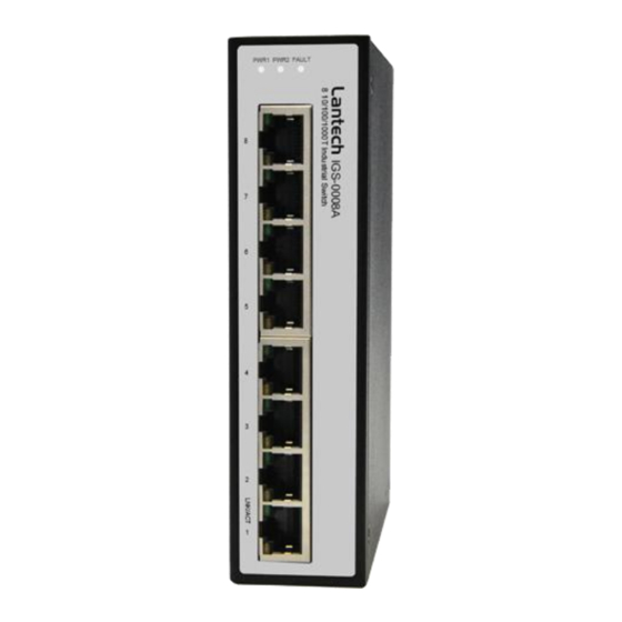
- Page 1 Lantech IGS-0008A 8 10/100/1000T Industrial Switch User Manual V1.00 Oct-2010...
-
Page 2: Table Of Contents
Content Overview ............1 Introduction ............. 1 Features ..............2 Packing List ............3 Safety Precaution ........... 3 Hardware Description ......... 4 Dimensions ............. 4 Wiring the Power Inputs .......... 5 LED Indicators ............6 RJ-45 Pin Assignments ........... 7 Cabling .............. -
Page 3: Overview
Overview Introduction The unmanaged industrial switch is a cost-effective solution and meets the high reliability requirements demanded by industrial applications. High-Speed Transmissions The Industrial switch includes a switch controller that can automatically sense transmission speeds (10/100/1000 Mbps). The RJ-45 interface can also be auto-detected, so MDI or MDI-X is automatically selected and a crossover cable is not required. -
Page 4: Features
Features Provides 8 x 10/100/1000Base-T Mbps Ethernet ports. Store-and-Forward switching architecture Back-plane (switching fabric): 16Gbps Third-generation Broadcom switch with AV function Guaranteed latency Guaranteed BW Synchronous timing Provides 192Kbits memory buffer 4K-entry MAC address table ... -
Page 5: Packing List
Packing List 1 x 8-port 10/100/1000Base-T Industrial Ethernet Switch 1 x User Manual 2 x Wall Mounting Brackets with screws Safety Precaution Attention If DC voltage is supplied by an external circuit, please use a protection device on the power supply input. -
Page 6: Hardware Description
Hardware Description In this paragraph, we will introduce the Industrial switch’s dimensions, port, cabling information, and wiring installation. Dimensions . The dimensions of the standard model that is not equipped with side heatsinks are 36.2 x 142 x 105 mm (W x H x D). The figure below gives the dimensions and views of each side of the 8-port 10/100/1000Base-T Industrial Switch. -
Page 7: Wiring The Power Inputs
Wiring the Power Inputs Please follow the steps below to insert the power wires. V+ V1- V+ V- 1. Insert the positive and negative wires into the V+ and V- contacts on the terminal block connector. 2. Tighten the wire-clamp screws to prevent the DC wires from loosing. -
Page 8: Led Indicators
LED Indicators The LED indicators located on the front panel display the power status and network status of the Industrial switch; each has their own specific meaning as the table shown below. Color Description Power input 1 is active Green Power input 1 is inactive Power input 2 is active Green... -
Page 9: Rj-45 Pin Assignments
RJ-45 Pin Assignments The UTP/STP ports will automatically sense for Fast Ethernet (10Base-T/100Base-TX) or Gigabit Ethernet (10Base-T/100Base-TX/1000Base-T) connection. Auto MDI/MDIX means that the switch can connect to another switch or workstation without changing straight through or crossover cabling. See the figures below for straight through and crossover cable schema. - Page 10 10/100Base-TX Cable Schema Straight Through Cable Schema Crossover Cable Schema 10/100/1000Base-T Pinouts The table below describes the gigabit Ethernet RJ-45 pinouts. Signal name Description BI_DA+ Bi-directional pair A+ BI_DA- Bi-directional pair A- BI_DB+ Bi-directional pair B+ BI_DC+ Bi-directional pair C+ BI_DC- Bi-directional pair C- BI_DB-...
-
Page 11: Cabling
10/100/1000Base-T Cable Schema The following two figures illustrate the 10/100/1000Base-T cable schema. Straight Through Cable Schema Crossover Cable Schema Cabling Use unshielded twisted-pair (UTP) or shielded twisted-pair (STP) cable for RJ-45 connections: 100Ω Category 3, 4 or 5 cable for 10Mbps connections, 100Ω... -
Page 12: Mounting Installation
Mounting Installation DIN-Rail Mounting Assembling the DIN-Rail Clip The DIN-rail clip is screwed on the industrial switch when out of factory. If not, please refer to the following steps and figure to secure the DIN-rail clip on the switch. 1, Use the screws to screw on the DIN-rail clip on the industrial switch. 2, To remove the DIN-rail clip, reverse step 1. - Page 13 Hanging the Industrial Switch Follow the steps below to hang the industrial switch on the DIN rail. 1, First, position the rear side of the switch directly in front of the DIN rail. Make sure the top of the clip hooks over the top of the DIN rail. 2, Push the unit downward.
-
Page 14: Wall-Mount Plate Mounting
Wall-Mount Plate Mounting Follow the steps below to mount the industrial switch with the wall mount plates included. 1. To remove the DIN-Rail clip from the industrial switch, unscrew the screws to remove the DIN-Rail clip. 2. Place the wall-mount plates on the rear panel of the industrial switch. 3. -
Page 15: Hardware Installation
Hardware Installation In this paragraph, we will describe how to install the 8-port 10/100/1000Base-TX Industrial Switch and the installation points for the attention. -
Page 16: Installation Steps
Installation Steps Unpacked the Industrial switch. Check the DIN-Rail is screwed on the Industrial switch. If the DIN-Rail is not screwed on the Industrial switch. Please refer to DIN-Rail Mounting section for DIN-Rail installation. If you want to wall mount the Industrial switch, then please refer to Wall-Mount Plate Mounting section for wall mount plate installation. - Page 17 Troubleshooting Verify that you are using the included or appropriate power cord/adapter. Don’t use the power adapter with DC output higher than the power rating of the device. Otherwise, the device will burn down. Select the proper UTP/STP cable to construct your network. Please check that you are using the right cable.
Need help?
Do you have a question about the IGS-0008A and is the answer not in the manual?
Questions and answers